Page 81 of 269

13B-81
AFTER REPAIRDeal with any faults displayed by the diagnostic tool.
Clear the computer fault memory.
Carry out a road test followed by another check with the diagnostic tool.
V6 MR-413-X44-13B000$110.mif
DIESEL INJECTION
Fault finding – Interpretation of faults13B
DCM 1.2 Injection
Program No.: 4D
Vdiag No.: 48, 4C, 50,
54, 58, 5C
DF050
CONTINUED
Check the insulation and continuity of the following connections:
–5A between components 160 and 120,
–BPT between components 160 and 645 (for Mégane II, Scénic II, Modus, and Clio III),
–BPT2 between components 160 and 645 (for Kangoo 2),
–SP17 between components 160 and 260 (for Kangoo 2),
–AP10 between components 160 and 1016 (for New Twingo),
–65A between components 160 and 645 (vehicle without ESP),
–65G between components 160 and 645 (vehicle with ESP).
If the connection or connections are faulty and there is a repair procedure (see Technical Note 6015A, Electrical
wiring repair, Wiring: Precautions for repair), repair the wiring, otherwise replace the wiring.
If the fault is still present, replace the brake switch, component code 160 (see MR 364 (Mégane II), MR 370
(Scénic II), MR 385 (Modus), MR 392 (Clio III), MR 411 (New Twingo), MR 417 (Kangoo 2), Mechanical, 37A,
Mechanical component controls, Brake light switch: Removal - Refitting).
If the fault is still present, contact the Techline.
Page 82 of 269

13B-82
AFTER REPAIRDeal with any faults displayed by the diagnostic tool.
Clear the computer fault memory.
Carry out a road test followed by another check with the diagnostic tool.
V6 MR-413-X44-13B000$110.mif
DIESEL INJECTION
Fault finding – Interpretation of faults13B
DCM 1.2 Injection
Program No.: 4D
Vdiag No.: 48, 4C, 50,
54, 58, 5C
DF051
PRESENT
OR
STOREDCRUISE CONTROL/SPEED LIMITER FUNCTION
1.DEF: Inconsistency
2.DEF: On - off switch
NOTESSpecial notes:
The cruise control function is inhibited.
See the Technical Note Wiring Diagrams for the vehicle.
Check the connection and condition of connector A (black 32-track) of the injection computer, component
code 160.
Check the connection and condition of the cruise control On - Off switch connections, component code 1081.
If the connector(s) is faulty and if there is a repair procedure (see Technical Note 6015A, Repairing electrical
wiring, Wiring: Precautions for repair), repair the connector, otherwise replace the wiring.
Check the insulation and continuity of the following connections:
–3FX between components 1081 and 120,
–3PD between components 1081 and 120.
If the connection or connections are faulty and there is a repair procedure (see Technical Note 6015A, Electrical
wiring repair, Wiring: Precautions for repair), repair the wiring, otherwise replace the wiring.
Check that the cruise control - speed limiter on - off switch is working (refer to the interpretation of ET042 Cruise
control - speed limiter).
If the fault is still present, contact the Techline.
DCM1.2_V48_DF051/DCM1.2_V4C_DF051/DCM1.2_V50_DF051/DCM1.2_V54_DF051/DCM1.2_V58_DF051/DCM1.2_V5C_DF051
Page 83 of 269

13B-83
AFTER REPAIRDeal with any faults displayed by the diagnostic tool.
Clear the computer fault memory.
Carry out a road test followed by another check with the diagnostic tool.
V6 MR-413-X44-13B000$110.mif
DIESEL INJECTION
Fault finding – Interpretation of faults13B
DCM 1.2 Injection
Program No.: 4D
Vdiag No.: 48, 4C, 50,
54, 58, 5C
DF052
PRESENT
OR
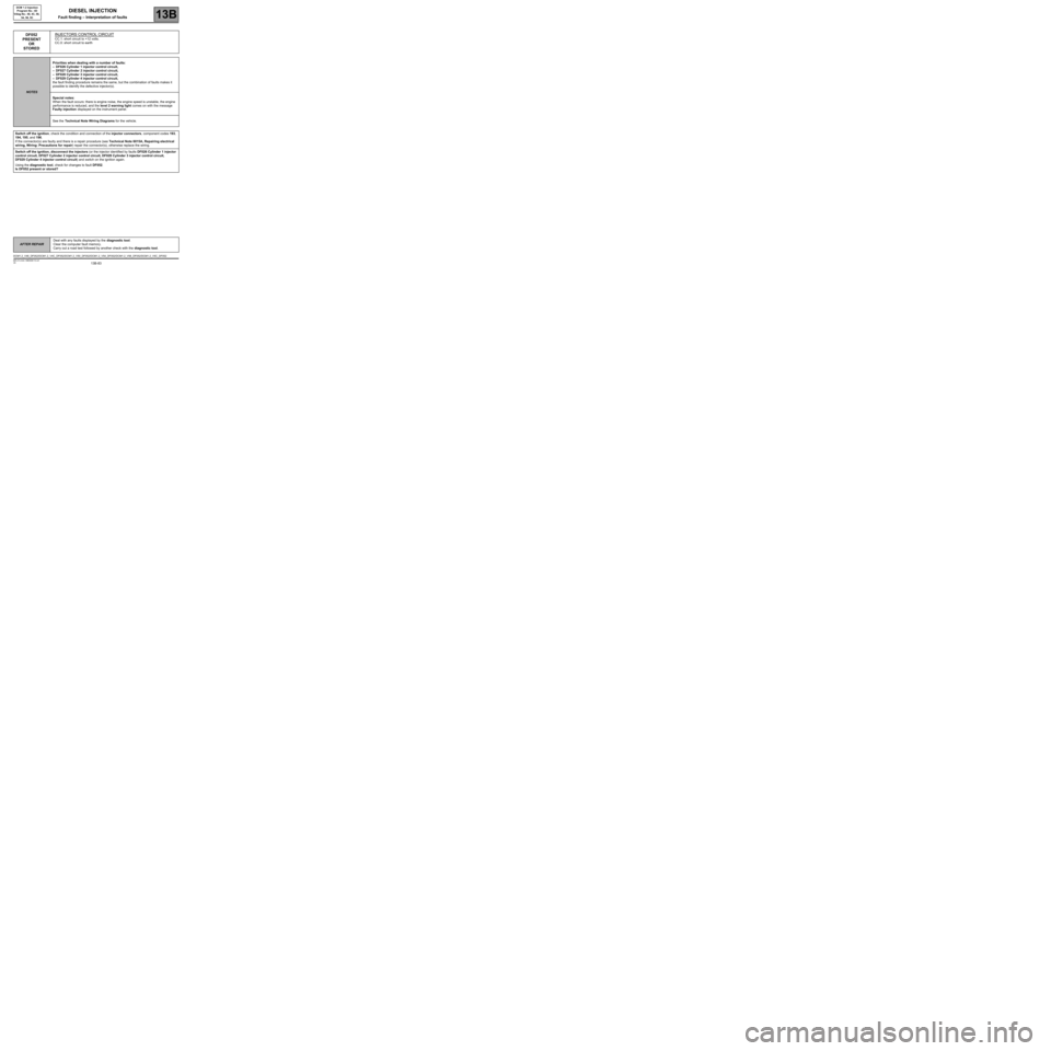
STOREDINJECTORS CONTROL CIRCUIT
CC.1: short circuit to +12 volts.
CC.0: short circuit to earth
NOTESPriorities when dealing with a number of faults:
–DF026 Cylinder 1 injector control circuit,
–DF027 Cylinder 2 injector control circuit,
–DF028 Cylinder 3 injector control circuit,
–DF029 Cylinder 4 injector control circuit,
the fault finding procedure remains the same, but the combination of faults makes it
possible to identify the defective injector(s).
Special notes:
When the fault occurs: there is engine noise, the engine speed is unstable, the engine
performance is reduced, and the level 2 warning light comes on with the message
Faulty injection displayed on the instrument panel.
See the Technical Note Wiring Diagrams for the vehicle.
Switch off the ignition, check the condition and connection of the injector connectors, component codes 193,
194, 195, and 196.
If the connector(s) are faulty and there is a repair procedure (see Technical Note 6015A, Repairing electrical
wiring, Wiring: Precautions for repair) repair the connector(s), otherwise replace the wiring.
Switch off the ignition, disconnect the injectors (or the injector identified by faults DF026 Cylinder 1 injector
control circuit, DF027 Cylinder 2 injector control circuit, DF028 Cylinder 3 injector control circuit,
DF029 Cylinder 4 injector control circuit) and switch on the ignition again.
Using the diagnostic tool, check for changes to fault DF052.
Is DF052 present or stored?
DCM1.2_V48_DF052/DCM1.2_V4C_DF052/DCM1.2_V50_DF052/DCM1.2_V54_DF052/DCM1.2_V58_DF052/DCM1.2_V5C_DF052
Page 84 of 269

13B-84
AFTER REPAIRDeal with any faults displayed by the diagnostic tool.
Clear the computer fault memory.
Carry out a road test followed by another check with the diagnostic tool.
V6 MR-413-X44-13B000$110.mif
DIESEL INJECTION
Fault finding – Interpretation of faults13B
DCM 1.2 Injection
Program No.: 4D
Vdiag No.: 48, 4C, 50,
54, 58, 5C
DF052
CONTINUED
DF052
PRESENTThe injectors are not defective.
Check the condition and connection of the injection computer (brown 48-track)
connector B.
If the connector is faulty and there is a repair procedure (see Technical Note 6015A,
Repairing electrical wiring, Wiring: Precautions for repair), repair the connector(s),
otherwise replace the wiring.
Check the insulation, the continuity and the absence of interference resistance on
the following connections:
–3L between components 193 and 120,
–3KW between components 193 and 120,
–3LA between components 194 and 120,
–3KX between components 194 and 120,
–3LB between components 195 and 120,
–3KY between components 195 and 120,
–3LC between components 196 and 120,
–3KZ between components 196 and 120.
If the connection or connections are faulty and there is a repair procedure
(see Technical Note 6015A, Electrical wiring repair, Wiring: Precautions for repair),
repair the wiring, otherwise replace the wiring.
If the fault is still present, contact the Techline.
DF052
STOREDInjector(s) defective.
Replace the injector identified by faults DF026 Cylinder 1 injector control circuit to
DF029 Cylinder 4 injector control circuit if any are present.
If none of the faults identifying the defective injector circuit are present:
–switch off the ignition,
–reconnect one of the four injectors,
–switch on the ignition again.
If the fault recurs as present, replace the reconnected injector, component code 193,
194, 195, or 196 (see MR 364 (Mégane II), MR 370 (Scénic II), MR 385 (Modus), MR
392 (Clio III), MR 411 (New Twingo), MR 417 (Kangoo 2), Mechanical, 13B,
Diesel injection, Diesel injector: Removal - Refitting).
Follow the same procedure for the other injectors.
Page 85 of 269

13B-85
AFTER REPAIRDeal with any faults displayed by the diagnostic tool.
Clear the computer fault memory.
Carry out a road test followed by another check with the diagnostic tool.
V6 MR-413-X44-13B000$110.mif
DIESEL INJECTION
Fault finding – Interpretation of faults13B
DCM 1.2 Injection
Program No.: 4D
Vdiag No.: 48, 4C, 50,
54, 58, 5C
DF053
PRESENT
OR
STOREDRAIL PRESSURE REGULATION FUNCTION
1.DEF: at minimum stop
2.DEF: at maximum stop
3.DEF: below minimum threshold
4.DEF: above maximum threshold
5.DEF: high flow current < minimum
6.DEF: high flow current > maximum
7.DEF: low flow current < minimum
8.DEF: low flow current > maximum
NOTESPriorities when dealing with a number of faults:
–DF098 Fuel temperature sensor circuit,
–DF007 Rail pressure sensor circuit.
Special note. If DF053, the engine may stop with the level 2 warning light illuminated
with the message Faulty injection displayed on the instrument panel.
Conditions for applying fault finding procedures to stored faults:
The fault is present with the engine running.
See the Technical Note Wiring Diagrams for the vehicle.
Check the presence and conformity of the fuel, run TEST 13: Diesel fuel conformity check.
Check the connection and condition of the flow actuator connector, component code 1105.
If the connector is faulty and there is a repair procedure (see Technical Note 6015A, Repairing electrical wiring,
Wiring: Precautions for repair), repair the connector, otherwise replace the wiring.
Check for + 12 V (after relay) on connection 3FB1 or 3FB2 (for New Twingo) or 3FB3 (for Kangoo 2) of
component 1105.
Check the connection and condition of connector B (brown 48-track) of the injection computer, component
code 120.
If the connector is faulty and there is a repair procedure (see Technical Note 6015A, Repairing electrical wiring,
Wiring: Precautions for repair), repair the connector, otherwise replace the wiring.
Measure the resistance between connections 3HI and 3FB1 or 3FB2 (for New Twingo) or 3FB3 (for Kangoo 2)
of component 1105.
If the resistance of the flow actuator is not between 4.8 Ω and 5.8 Ω at 20
°C, replace the flow actuator, component
code 1105 (see MR 364 (Mégane II), MR 370 (Scénic II), MR 385 (Modus), MR 392 (Clio III), MR 411
(New Twingo), MR 417 (Kangoo 2), Mechanical, 13B, Diesel injection, Flow actuator: Removal - Refitting).
DCM1.2_V48_DF053/DCM1.2_V4C_DF053/DCM1.2_V50_DF053/DCM1.2_V54_DF053/DCM1.2_V58_DF053/DCM1.2_V5C_DF053
Page 86 of 269
13B-86
AFTER REPAIRDeal with any faults displayed by the diagnostic tool.
Clear the computer fault memory.
Carry out a road test followed by another check with the diagnostic tool.
V6 MR-413-X44-13B000$110.mif
DIESEL INJECTION
Fault finding – Interpretation of faults13B
DCM 1.2 Injection
Program No.: 4D
Vdiag No.: 48, 4C, 50,
54, 58, 5C
DF053
CONTINUED
Check the insulation and continuity of the following connection:
–3HI between components 1105 and 120.
If the connection or connections are faulty and there is a repair procedure (see Technical Note 6015A, Electrical
wiring repair, Wiring: Precautions for repair), repair the wiring, otherwise replace the wiring.
Run Test 1: Low pressure circuit check.
Run Test 6: High pressure system check.
Run Test 8: Injector return flow.
If the fault is still present contact Techline.
Page 87 of 269

13B-87
AFTER REPAIRDeal with any faults displayed by the diagnostic tool.
Clear the computer fault memory.
Carry out a road test followed by another check with the diagnostic tool.
V6 MR-413-X44-13B000$110.mif
DIESEL INJECTION
Fault finding – Interpretation of faults13B
DCM 1.2 Injection
Program No.: 4D
Vdiag No.: 48, 4C, 50,
54, 58, 5C
DF056
PRESENT
OR
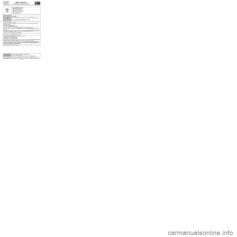
STOREDAIR FLOWMETER CIRCUIT1.DEF: Permanent low level
2.DEF: Permanent high level
3.DEF: Below minimum threshold
4.DEF: Above maximum threshold
5.DEF: At minimum stop
6.DEF: At maximum stop
NOTESSpecial notes:
If fault DF056 is present: air flow regulation stops and the EGR valve is closed.
See the Technical Note Wiring Diagrams for the vehicle.
Check that the air filter is not blocked.
Check that the air filter is not clogged and that the air inlet system is not blocked between the air filter outlet
and the inlet manifold.
Run TEST 5: Inlet circuit check.
Run TEST 11: Air line at the turbocharger.
Check the connection and condition of the air flowmeter connector, component code 799.
Check the connection and condition of connector B (brown 48-track) of the injection computer, component
code 120.
If the connector(s) is faulty and if there is a repair procedure (see Technical Note 6015A, Repairing electrical
wiring, Wiring: Precautions for repair), repair the connector, otherwise replace the wiring.
Check for + 5 V on connection 3KJ of component 799.
Check for earth on connection 3DW of component 799.
Check the insulation and continuity of the following connections:
–3KJ between components 799 and 120,
–3DW between components 799 and 120,
–3DV between components 799 and 120.
If the connection or connections are faulty and there is a repair procedure (see Technical Note 6015A, Electrical
wiring repair, Wiring: Precautions for repair), repair the wiring, otherwise replace the wiring.
If the fault is still present, replace the air flowmeter, component code 799 (see MR 364 (Mégane II), MR 370
(Scénic II), MR 385 (Modus), MR 392 (Clio III), MR 411 (New Twingo), MR 417 (Kangoo 2), Mechanical, 12A,
Fuel mixture, Air flowmeter: Removal - Refitting).
If the fault is still present, contact the Techline.
DCM1.2_V48_DF056/DCM1.2_V4C_DF056/DCM1.2_V50_DF056/DCM1.2_V54_DF056/DCM1.2_V58_DF056/DCM1.2_V5C_DF056
Page 88 of 269

13B-88
AFTER REPAIRDeal with any faults displayed by the diagnostic tool.
Clear the computer fault memory.
Carry out a road test followed by another check with the diagnostic tool.
V6 MR-413-X44-13B000$110.mif
DIESEL INJECTION
Fault finding – Interpretation of faults13B
DCM 1.2 Injection
Program No.: 4D
Vdiag No.: 48, 4C, 50,
54, 58, 5C
DF057
PRESENT
OR
STOREDWATER IN DIESEL FUEL DETECTOR CIRCUIT
CO.1: Open circuit or short circuit to + 12 V
CC.0: Short circuit to earth
1.DEF: above maximum threshold
NOTESSpecial notes:
–If water is detected downstream of the diesel filter, the high pressure pump
and the injectors may be damaged.
Use bornier Elé. 1681 for all operations on the connector of the engine management
computer.
See the Technical Note Wiring Diagrams for the vehicle.
Check the connections of the water in diesel fuel sensor, component code 414.
Check the connections of the engine management computer, component code 120.
If the connector(s) are faulty and there is a repair procedure (see Technical Note 6015A, Repairing electrical
wiring, Wiring: Precautions for repair) repair the connector(s), otherwise replace the wiring.
With the ignition on, check for +12 V on connections 3FB1 and 3FB2 (for New Twingo) or AP15 (for Kangoo 2)
of component 414.
Check for earth on the following connections:
–M or 3WU (for New Twingo) of component 120.
–MH and MW (for Kangoo 2) of component 414.
Check the continuity of the following connections:
–3WT between components 414 and 120,
–M between components 414 and 120,
–3FB1 between components 414 and 1337.
(only for New Twingo):
–3WT between components 414 and 120,
–3WU between components 414 and 120,
–3FB2 between components 414 and 238.
(only for Kangoo 2):
–AP15 between components 414 and 1337,
–3WT between components 414 and 1337,
–MH and MW between earth and component 414.
If the connection or connections are faulty and there is a repair procedure (see Technical Note 6015A, Electrical
wiring repair, Wiring: Precautions for repair), repair the wiring, otherwise replace the wiring.
DCM1.2_V48_DF057/DCM1.2_V4C_DF057/DCM1.2_V50_DF057/DCM1.2_V54_DF057/DCM1.2_V58_DF057/DCM1.2_V5C_DF057