Page 265 of 348

17B-265V7 MR-413-X44-17B000$171.mif
17B
SIM 32 Injection
Program no.: D3
Vdiag No.: 44, 4C, 50
and 54
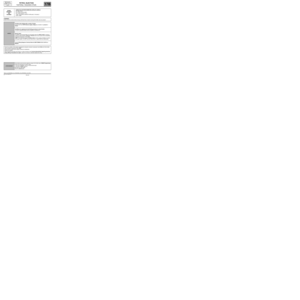
PR014IDLE SPEED CORRECTION
PARAMETER
DEFINITIONThis parameter indicates the engine's rotational speed in rpm.
NOTESSpecial notes:
Only perform these tests if the parameters do not correspond with the system operation
programming.
Conformity check with engine stopped and ignition on, or engine running and engine coolant
temperature > 80˚C
This status indicates the engine idle speed correction value.
The value should be between:
0 rpm < PR014 < 224 rpm.
The idle speed regulator performs all of the calculations that allow the idle speed actuator to be controlled
physically: the motorised throttle. The functional component of the regulator is adaptive (variation programming
and ageing).
SIM32_V44_PR014/SIM32_V4C_PR014/SIM32_V50_PR014/SIM32_V54_PR014
PETROL INJECTION
Fault finding – Interpretation of parameters
AFTER REPAIRCarry out a road test followed by a check with the diagnostic tool.
Page 266 of 348
17B-266V7 MR-413-X44-17B000$171.mif
PETROL INJECTION
Fault finding – Interpretation of parameters17B
SIM 32 Injection
Program no.: D3
Vdiag No.: 44, 4C, 50
and 54
PR015ENGINE TORQUE
PARAMETER
DEFINITIONThis parameter indicates the engine torque in Nm.
NOTESSpecial notes:
Only perform these tests if the parameters do not correspond with the system operation
programming.
Conformity check with the engine running and engine coolant temperature > 80˚C
This value should be between:
20 < X < 40 N.m
This parameter is only valid when the engine is running.
SIM32_V44_PR015/SIM32_V4C_PR015/SIM32_V50_PR015/SIM32_V54_PR015
AFTER REPAIRCarry out a road test followed by a check with the diagnostic tool.
Page 267 of 348
17B-267V7 MR-413-X44-17B000$171.mif
PETROL INJECTION
Fault finding – Interpretation of parameters17B
SIM 32 Injection
Program no.: D3
Vdiag No.: 44, 4C, 50
and 54
PR018ESTIMATED AIR FLOW
PARAMETER
DEFINITIONThis parameter indicates the inlet air flow in kg/h.
NOTESSpecial notes:
Only perform these tests if the parameters do not correspond with the system operation
programming.
There must be no faults present.
Perform this fault finding procedure:
–after finding an inconsistency in the parameter,
–or after a customer complaint (lack of power, smoke etc.).
Conformity check with engine stopped and ignition on.
Indicates the inlet air flow in kg/h.
The value should be:
X = 0 kg/h
Conformity check with the engine running and engine coolant temperature > 80˚C
Indicates the inlet air flow in kg/h.
The value should be:
X ≈ 7 kg/h
SIM32_V44_PR018/SIM32_V4C_PR018/SIM32_V50_PR018/SIM32_V54_PR018
AFTER REPAIRCarry out a road test followed by a check with the diagnostic tool.
Page 268 of 348

17B-268V7 MR-413-X44-17B000$171.mif
PETROL INJECTION
Fault finding – Interpretation of parameters17B
SIM 32 Injection
Program no.: D3
Vdiag No.: 44, 4C, 50
and 54
PR030ACCELERATOR PEDAL POSITION
PARAMETER
DEFINITIONThis parameter indicates the accelerator pedal position in %.
NOTESSpecial notes:
Only carry out these checks if PR030 > 15% with No load or if PR030 < 90% with
Full load.
Use the Wiring Diagrams Technical Note for NEW TWINGO, E33, CLIO III or
MODUS.
Conformity check with engine stopped and ignition on, or engine running, and engine coolant
temperature > 80˚C
If there is no pressure on the pedal X = 0%
In the event of a fault, consult the interpretation of fault DF196 Pedal sensor circuit gang 1 or DF198 Pedal
sensor circuit gang 2.
Sensor electrical conformity
Check that the pedal mechanism has not seized.
Check the condition of the accelerator potentiometer connector (component code 921) and the engine
management computer connector (component code 120).
If the connector or connectors are faulty and if there is a repair procedure (see Technical Note 6015A, Repairing
electrical wiring, Wiring: Precautions for repair), repair the connector, otherwise replace the wiring.
SIM32_V44_PR030/SIM32_V4C_PR030/SIM32_V50_PR030/SIM32_V54_PR030
AFTER REPAIRCarry out a road test followed by a check with the diagnostic tool.
Page 269 of 348
17B-269V7 MR-413-X44-17B000$171.mif
PETROL INJECTION
Fault finding – Interpretation of parameters17B
SIM 32 Injection
Program no.: D3
Vdiag No.: 44, 4C, 50
and 54
PR030
CONTINUED
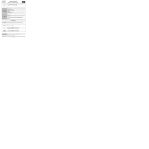
Use the universal bornier to check the insulation and continuity of the following connections:
●3LT between the components 120 and 921,
●3LR between the components 120 and 921,
●3LS between the components 120 and 921,
●3LU between the components 120 and 921,
●3LV between components 120 and 921,
●3LW between components 120 and 921.
If the connection or connections are faulty and there is a repair procedure (see Technical Note 6015A, Electrical
wiring repair, Wiring: Precautions for repair), repair the wiring, otherwise replace it.
If the fault is still present, replace the pedal potentiometer.
AFTER REPAIRCarry out a road test followed by a check with the diagnostic tool.
Page 270 of 348

17B-270V7 MR-413-X44-17B000$171.mif
PETROL INJECTION
Fault finding – Interpretation of parameters17B
SIM 32 Injection
Program no.: D3
Vdiag No.: 44, 4C, 50
and 54
PR035ATMOSPHERIC PRESSURE
PARAMETER
DEFINITIONThis parameter indicates the atmospheric pressure in bar. The sensor is integrated in
the computer.
NOTESSpecial notes:
Only perform these tests if the parameters do not correspond with the system operation
programming.
Use the Wiring Diagrams Technical Note for NEW TWINGO, E33, CLIO III
or MODUS.
Conformity check with engine stopped and ignition on, or engine running, and engine coolant
temperature > 80˚C
The atmospheric pressure value is:
PR035 ≈ 1 bar +/- 0.20 bar
In the event of a fault, consult the interpretation of DF004 Turbocharging pressure sensor circuit.
Check the cleanliness and condition of the atmospheric pressure sensor and its connections (component
code 147) and the engine management computer (component code 120).
If the connector or connectors are faulty and if there is a repair procedure (see Technical Note 6015A, Repairing
electrical wiring, Wiring: Precautions for repair), repair the connector, otherwise replace the wiring.
On the atmospheric pressure sensor, component code 147, check the resistance between connections 3LG
and 3CK.
If the resistance is not X 50 kΩ, replace the sensor.
SIM32_V44_PR035/SIM32_V4C_PR035/SIM32_V50_PR035/SIM32_V54_PR035
AFTER REPAIRCarry out a road test followed by a check with the diagnostic tool.
Page 271 of 348
17B-271V7 MR-413-X44-17B000$171.mif
PETROL INJECTION
Fault finding – Interpretation of parameters17B
SIM 32 Injection
Program no.: D3
Vdiag No.: 44, 4C, 50
and 54
PR035
CONTINUED
Use the universal bornier to check the insulation and continuity of the following connections:
●3LG between components 120 and 147,
●3F between components 120 and 147,
●3CK between components 120 and 147.
If the connection or connections are faulty and there is a repair procedure (see Technical Note 6015A, Electrical
wiring repair, Wiring: Precautions for repair), repair the wiring, otherwise replace it.
If the fault is still present, replace the atmospheric pressure sensor.
If the fault is still present, contact the Techline.
AFTER REPAIRCarry out a road test followed by a check with the diagnostic tool.
Page 272 of 348
17B-272V7 MR-413-X44-17B000$171.mif
PETROL INJECTION
Fault finding – Interpretation of parameters17B
SIM 32 Injection
Program no.: D3
Vdiag No.: 44, 4C, 50
and 54
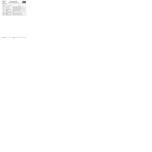
PR037REFRIGERANT PRESSURE
NOTESSpecial notes:
Only perform these tests if the parameters do not correspond with the system operation
programming.
Conformity check with the engine running and engine coolant temperature > 80˚C
The value should be between:
1 bar < PR037 < 40 bar.
In the event of a fault, test the multiplex network (see 88B, Multiplex).
SIM32_V44_PR037/SIM32_V4C_PR037/SIM32_V50_PR037/SIM32_V54_PR037
AFTER REPAIRCarry out a road test followed by a check with the diagnostic tool.