Page 3799 of 4331
PREPARATION
MT-5
< SERVICE INFORMATION >
[RS5F91R] D
E
F
G H
I
J
K L
M A
B MT
N
O P
Commercial Service Tools
INFOID:0000000004784218
KV40100900
( — )
Drift Installing input shaft front bearing
a: 52 mm (2.05 in) dia.
a: 39.5 mm (1.55 in) dia.
KV32300QAE
( — )
Drift Installing differential side bearing outer race
a: 65 mm (2.56 in) dia.
a: 63 mm (2.48 in) dia.
ST33052000
( — )
Drift Removing differential side bearing
a: 22 mm (0.87 in) dia.
a: 28 mm (1.10 in) dia.
KV40104920
( — )
Drift Installing differential side bearing
a: 21.7 mm (0.85 in) dia.
a: 44.7 mm (1.76 in) dia.
Tool number
(Kent-Moore No.)
Tool name Description NT084
SCIA1783J
ZZA0969D
ZZA0969D
Tool name Description
Drift Removing input shaft front bearing
a: 38 mm (1.50 in) dia.
Drift Installing bushing
a: 14.5 mm (0.571 in) dia. S-NT063
S-NT063
Page 3831 of 4331
MT
N
O P
MAINSHAFT AND GEAR
Disassembly and Assembly INFOID:0000000004788551
GENERAL PRECAUTIONS • Never reuse snap ring.
• Secure mainshaft in a vise with backplate, and then remove gears and snap rings.
• For installation and removal of snap ring, set snap ring pliers and flat pliers at both sides of snap ring. While expanding snap ring
with snap ring pliers, move snap ring with flat pliers.
• Disassemble gear components putting direction marks on the parts that never affect any functions.
DISASSEMBLY 1. Remove 3rd-4th synchronizer hub and 3rd baulk ring.
2. Remove snap ring (1) and thrust washer (2) using suitable tools.
3. Remove 3rd main gear (1) and thrust washer (2).
4. Remove snap ring (1) and thrust washer (2) using suitable tools.
Page 3839 of 4331

MT
N
O P
PREPARATION
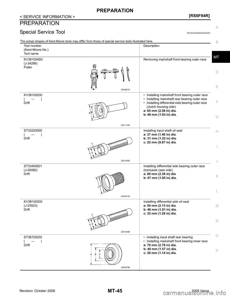
Special Service Tool INFOID:0000000004305267
The actual shapes of Kent-Moore tools may differ fr om those of special service tools illustrated here.
Tool number
(Kent-Moore No.)
Tool name Description
KV381054S0
(J-34286)
Puller Removing mainshaft front bearing outer race
KV38100200
( — )
Drift • Installing mainshaft front bearing outer race
• Installing mainshaft rear bearing outer race
• Installing differential side bearing outer race
(clutch housing side)
a: 65 mm (2.56 in) dia.
b: 49 mm (1.93 in) dia .
ST33220000
( — )
Drift Installing input shaft oil seal
a: 37 mm (1.46 in) dia .
b: 31 mm (1.22 in) dia.
c: 22 mm (0.87 in) dia.
ST33400001
(J-26082)
Drift Installing differential side bearing outer race
(transaxle case side)
a: 60 mm (2.36 in) dia .
b: 47 mm (1.85 in) dia.
KV38100300
(J-25523)
Drift Installing differential side oil seal
a: 54 mm (2.13 in) dia .
b: 46 mm (1.81 in) dia.
c: 32 mm (1.26 in) dia.
ST36720030
( — )
Drift • Installing input shaft rear bearing
• Installing mainshaft front bearing inner race
a: 70 mm (2.76 in) dia.
b: 40 mm (1.57 in) dia.
c: 29 mm (1.14 in) dia. ZZA1143D
ZZA1046D
ZZA1046D
ZZA0978D
Page 3888 of 4331

MTC
N
O P
SERVICE INFORMATION
PRECAUTIONS
Precaution for Supplemental Restraint System (SRS) "AIR BAG" and "SEAT BELT
PRE-TENSIONER" INFOID:0000000004784399
The Supplemental Restraint System such as “A IR BAG” and “SEAT BELT PRE-TENSIONER”, used along
with a front seat belt, helps to reduce the risk or severi ty of injury to the driver and front passenger for certain
types of collision. This system includes seat belt switch inputs and dual stage front air bag modules. The SRS
system uses the seat belt switches to determine the front air bag deployment, and may only deploy one front
air bag, depending on the severity of a collision and w hether the front occupants are belted or unbelted.
Information necessary to service the system safely is included in the SRS and SB section of this Service Man-
ual.
WARNING:
• To avoid rendering the SRS inoper ative, which could increase the risk of personal injury or death in
the event of a collision which would result in air bag inflation, all maintenance must be performed by
an authorized NISSAN/INFINITI dealer.
• Improper maintenance, including in correct removal and installation of the SRS can lead to personal
injury caused by unintentional act ivation of the system. For removal of Spiral Cable and Air Bag
Module, see the SRS section.
• Do not use electrical test equipm ent on any circuit related to the SRS unless instructed to in this
Service Manual. SRS wiring harnesses can be identi fied by yellow and/or orange harnesses or har-
ness connectors.
PRECAUTIONS WHEN USING POWER TOOLS (AIR OR ELECTRIC) AND HAMMERS WARNING:
• When working near the Airbag Diagnosis Sensor Un it or other Airbag System sensors with the Igni-
tion ON or engine running, DO NOT use air or el ectric power tools or strike near the sensor(s) with a
hammer. Heavy vibration could activate the sensor( s) and deploy the air bag(s), possibly causing
serious injury.
• When using air or electric power tools or hammers , always switch the Ignition OFF, disconnect the
battery, and wait at least 3 minutes before performing any service.
Precaution Necessary for Steering Wh eel Rotation After Battery Disconnect
INFOID:0000000004687764
NOTE:
• This Procedure is applied only to models with Inte lligent Key system and NATS (NISSAN ANTI-THEFT SYS-
TEM).
• Remove and install all control units after disconnecti ng both battery cables with the ignition knob in the
″ LOCK ″ position.
• Always use CONSULT-III to perform self-diagnosis as a part of each function inspection after finishing work.
If DTC is detected, perform trouble diagnosis according to self-diagnostic results.
For models equipped with the Intelligent Key system and NATS , an electrically controlled steering lock mech-
anism is adopted on the key cylinder.
For this reason, if the battery is disconnected or if the battery is discharged, the steering wheel will lock and
steering wheel rotation will become impossible.
If steering wheel rotation is required when battery pow er is interrupted, follow the procedure below before
starting the repair operation.
OPERATION PROCEDURE 1. Connect both battery cables. NOTE:
Supply power using jumper cables if battery is discharged.
2. Use the Intelligent Key or mechanical key to turn the ignition switch to the ″ACC ″ position. At this time, the
steering lock will be released.
3. Disconnect both battery cables. The steering lock will remain released and the steering wheel can be
rotated.
4. Perform the necessary repair operation.
Page 3964 of 4331

MTC
N
O P
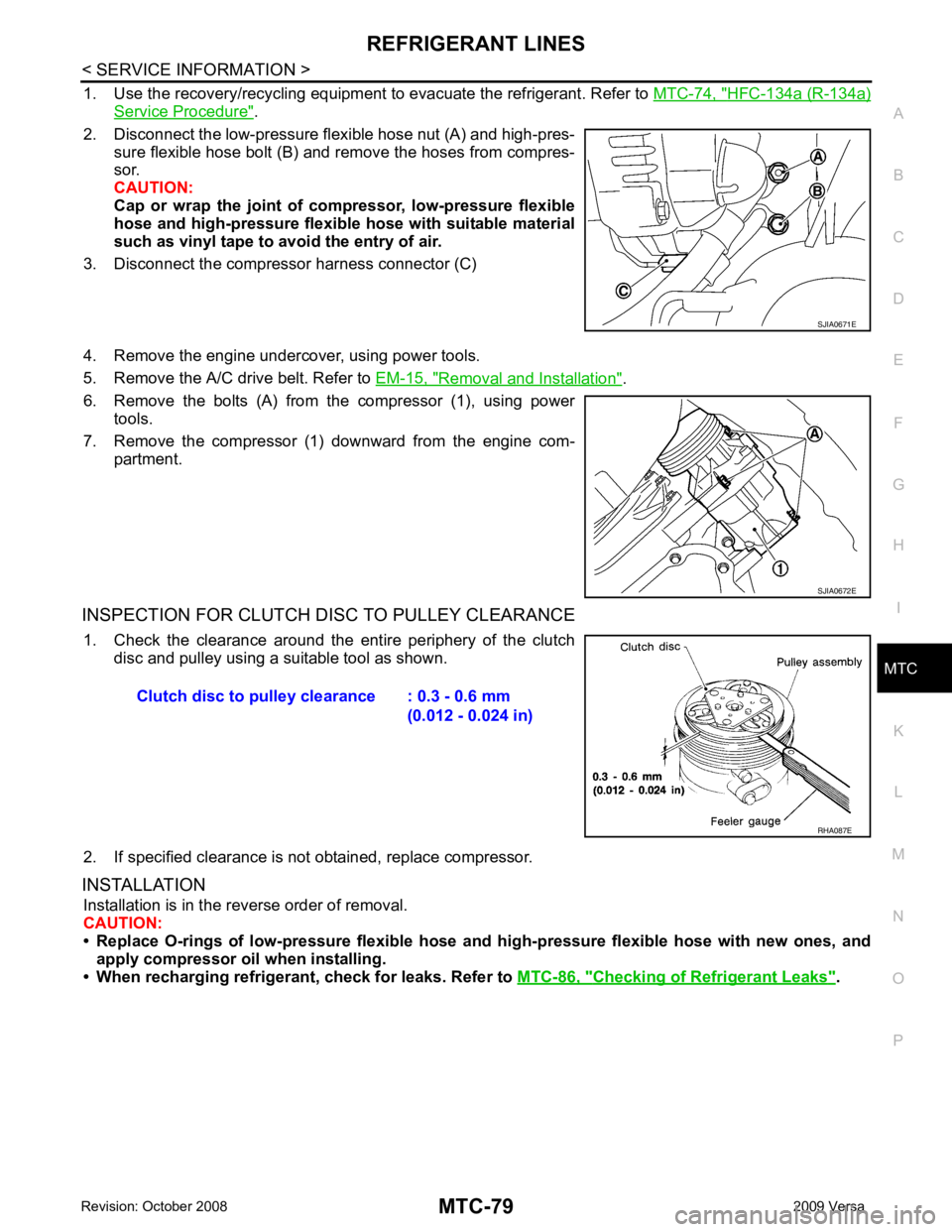
1. Use the recovery/recycling equipment
to evacuate the refrigerant. Refer to MTC-74, " HFC-134a (R-134a)
Service Procedure " .
2. Disconnect the low-pressure flexible hose nut (A) and high-pres- sure flexible hose bolt (B) and remove the hoses from compres-
sor.
CAUTION:
Cap or wrap the joint of co mpressor, low-pressure flexible
hose and high-pressure flexible hose with suitable material
such as vinyl tape to avoid the entry of air.
3. Disconnect the compressor harness connector (C)
4. Remove the engine undercover, using power tools.
5. Remove the A/C drive belt. Refer to EM-15, " Removal and Installation " .
6. Remove the bolts (A) from the compressor (1), using power tools.
7. Remove the compressor (1) downward from the engine com- partment.
INSPECTION FOR CLUTCH DISC TO PULLEY CLEARANCE 1. Check the clearance around the entire periphery of the clutch disc and pulley using a suitable tool as shown.
2. If specified clearance is not obtained, replace compressor.
INSTALLATION Installation is in the reverse order of removal.
CAUTION:
• Replace O-rings of low-pressure flexible hose and high-pressure flexible hose with new ones, and
apply compressor oil when installing.
• When recharging refrigeran t, check for leaks. Refer to MTC-86, " Checking of Refrigerant Leaks " .
Page 3965 of 4331
HFC-134a (R-134a)
Service Procedure " .
2. Remove the nut (A) for the low-pressure flexible hose (1) and the bolt (B) for the high-pressure flexible hose (2) and remove
the hoses from the compressor.
CAUTION:
Cap or wrap the joint of co mpressor, low-pressure flexible
hose and high-pressure flexibl e hose with suitable material
such as vinyl tape to avoid the entry of air.
3. Remove the engine undercover, using power tools.
4. Remove A/C compressor belt. Refer to EM-136, " Removal and Installation " .
5. Disconnect compressor connector.
6. Remove bolts (A) from compressor (1), using power tools.
7. Remove compressor (1) downward from the engine compart- ment. SJIA0672E
Page 4060 of 4331
PS-4< SERVICE INFORMATION >
PREPARATION
PREPARATION
Special Service Tool INFOID:0000000004305928
The actual shapes of K ent-Moore tools may differ from thos e of special tools illustrated here.
Commercial Service Tool INFOID:0000000004305929
Tool number
(Kent-Moore No.)
Tool name Description
ST3127S000
(J-25742-1)
Preload gauge
(J-25765-A)
1. GG91030000
Torque wrench
2. HT62940000
( — )
Socket adapter (1/2")
3. HT62900000
( — )
Socket adapter (3/8") Inspecting rotating torque for steering column
assembly and pinion assembly
KV40107300
( — )
Boot Band crimping tool Installing boot bands
KV48103400
( — )
Preload adapter Inspecting of rotating torque for pinion assem-
bly S-NT541
ZZA1229D
ZZA0824D
Tool number
Tool name Description
Spring gauge Inspecting steering wheel turning force and
power steering gear linkage
Power tool Removing nuts and bolts LST025
PBIC0190E
Page 4071 of 4331

PS
N
O P
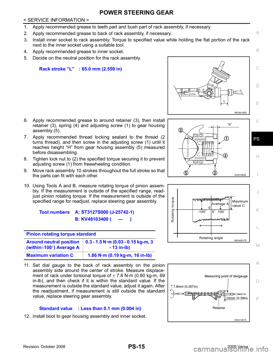
1. Apply recommended grease to teeth part and bush part of rack assembly, if necessary.
2. Apply recommended grease to back of rack assembly, if necessary.
3. Install inner socket to rack assembly. Torque to specified value while holding the flat portion of the rack next to the inner socket using a suitable tool.
4. Apply recommended grease to inner socket.
5. Decide on the neutral position for the rack assembly.
6. Apply recommended grease to around retainer (3), then install retainer (3), spring (4) and adjusting screw (1) to gear housing
assembly (5).
7. Apply recommended thread locking sealant to the thread (2 turns thread), and then screw in the adjusting screw (1) until it
reaches height “H” from gear housing assembly (5) measured
before disassembling.
8. Tighten lock nut to (2) the specified torque securing it to prevent adjusting screw (1) from freewheeling condition.
9. Move rack assembly 10 strokes throughout the full stroke so that the parts can fit with each other.
10. Using Tools A and B, measure rotating torque of pinion assem- bly. If the measurement is outside of the specified range, read-
just pinion rotating torque. If the measurement is outside of the
specified range for readjust, replace steering gear assembly.
11. Set dial gauge to the back of rack assembly on the pinion assembly side around the center of stroke. Measure displace-
ment of rack under torsional torque of ± 7.8 N·m (0.80 kg-m, 69
in-lb), and then check if it is within the standard value. If the
measurement is outside the standard value, adjust it again. After
the readjustment, if measurement is still outside the standard
value, replace steering gear assembly.
12. Install boot to gear housing assembly and inner socket. Rack stroke “L” : 65.0 mm (2.559 in)