Page 3252 of 4331

FSU-18< SERVICE INFORMATION >
SERVICE DATA AND SPECIFICATIONS (SDS)
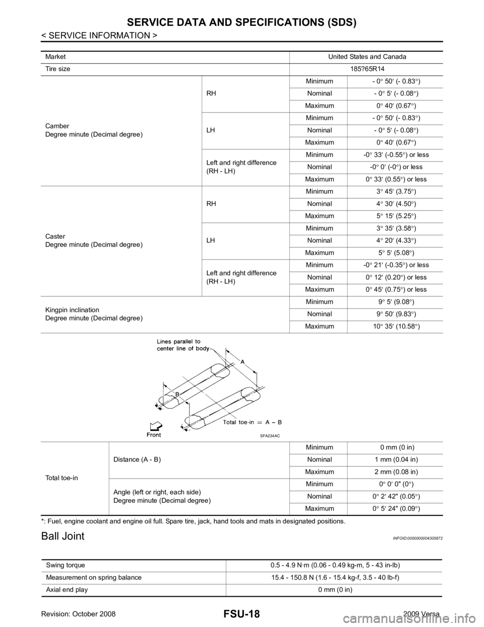
*: Fuel, engine coolant and engine oil full. Spare tire, jack, hand tools and mats in designated positions.
Ball Joint INFOID:0000000004305872
Market
United States and Canada
Tire size 185?65R14
Camber
Degree minute (Decimal degree) RH
Minimum - 0
° 50 ′ (- 0.83 °)
Nominal - 0 ° 5 ′ (- 0.08 °)
Maximum 0 ° 40 ′ (0.67 °)
LH Minimum - 0
° 50 ′ (- 0.83 °)
Nominal - 0 ° 5 ′ (- 0.08 °)
Maximum 0 ° 40 ′ (0.67 °)
Left and right difference
(RH - LH) Minimum -0
° 33 ′ (-0.55 °) or less
Nominal -0 ° 0 ′ (-0 °) or less
Maximum 0 ° 33 ′ (0.55 °) or less
Caster
Degree minute (Decimal degree) RH
Minimum 3
° 45 ′ (3.75 °)
Nominal 4 ° 30 ′ (4.50 °)
Maximum 5 ° 15 ′ (5.25 °)
LH Minimum 3
° 35
′ (3.58 °)
Nominal 4 ° 20 ′ (4.33 °)
Maximum 5 ° 5 ′ (5.08 °)
Left and right difference
(RH - LH) Minimum -0
° 21 ′ (-0.35 °) or less
Nominal 0 ° 12 ′ (0.20 °) or less
Maximum 0 ° 45 ′ (0.75 °) or less
Kingpin inclination
Degree minute (Decimal degree) Minimum 9
° 5 ′ (9.08 °)
Nominal 9 ° 50 ′ (9.83 °)
Maximum 10 ° 35 ′ (10.58 °)
Total toe-in Distance (A - B)
Minimum 0 mm (0 in)
Nominal 1 mm (0.04 in)
Maximum 2 mm (0.08 in)
Angle (left or right, each side)
Degree minute (Decimal degree) Minimum 0
° 0 ′ 0" (0 °)
Nominal 0 ° 2 ′ 42" (0.05 °)
Maximum 0 ° 5 ′ 24" (0.09 °) SFA234AC
Swing torque 0.5 - 4.9 N·m (0.0 6 - 0.49 kg-m, 5 - 43 in-lb)
Measurement on spring balance 15.4 - 150.8 N (1.6 - 15.4 kg-f, 3.5 - 40 lb-f)
Axial end play 0 mm (0 in)
Page 3253 of 4331
FSU
N
O P
Wheelarch Height (Unladen*)
INFOID:0000000004305873
*: Fuel, engine coolant and engine oil full. Spare tire, jack, hand tools and mats in designated positions. Market United States Canada
United States
and Canada
Tire size 185/65R15 185/65R14
Front (Hf) 685 mm (26.97 in) 685 (26.97) 677 (26.65)
Rear (Hr) 682 mm (26.85 in) 683 (26.89) 681 (26.81)
Page 3257 of 4331

GI-4< SERVICE INFORMATION >
PRECAUTIONS
• Replace oil seals, gaskets, packings, O-rings, locking wa shers, cotter pins, self-locking nuts, etc. with new
ones.
• Replace inner and outer races of tapered roller bearings and needle bearings as a set.
• Arrange the disassembled parts in accordance with their assembled locations and sequence.
• Do not touch the terminals of electrical com ponents which use microcomputers (such as ECM).
Static electricity may damage internal electronic components.
• After disconnecting vacuum or air hoses, atta ch a tag to indicate the proper connection.
• Use only the fluids and lubricants specified in this manual.
• Use approved bonding agent, sealants or their equivalents when required.
• Use hand tools, power tools (disassembly only) and recommended
special tools where specified for safe and efficient service repairs.
• When repairing the fuel, oil, water, vacuum or exhaust systems, check all affected lines for leaks.
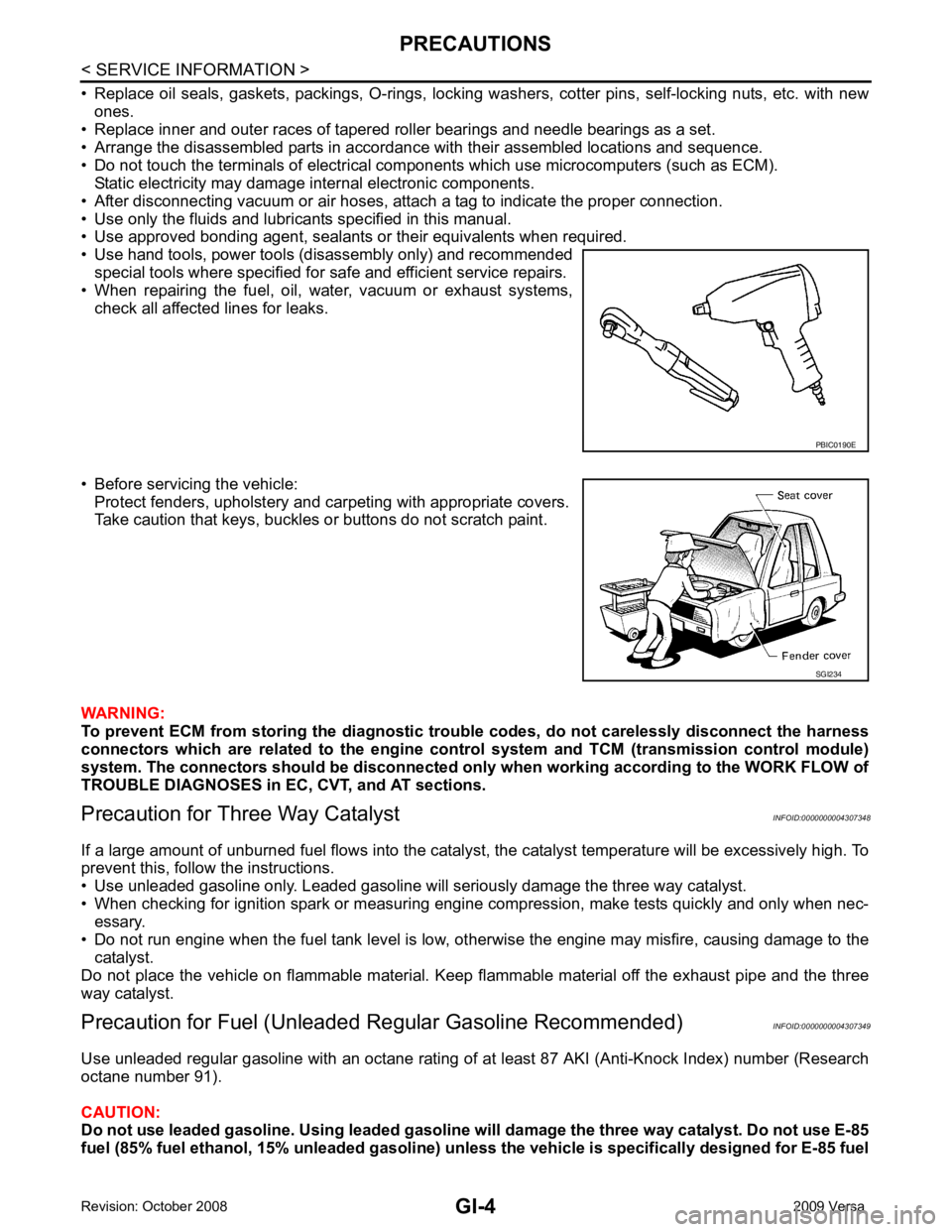
• Before servicing the vehicle: Protect fenders, upholstery and carpeting with appropriate covers.
Take caution that keys, buckles or buttons do not scratch paint.
WARNING:
To prevent ECM from storing the diagnostic tro uble codes, do not carelessly disconnect the harness
connectors which are related to the engine cont rol system and TCM (transmission control module)
system. The connectors should be disconnected on ly when working according to the WORK FLOW of
TROUBLE DIAGNOSES in EC, CVT, and AT sections.
Precaution for Three Way Catalyst INFOID:0000000004307348
If a large amount of unburned fuel flows into the catalyst , the catalyst temperature will be excessively high. To
prevent this, follow the instructions.
• Use unleaded gasoline only. Leaded gasoline will seriously damage the three way catalyst.
• When checking for ignition spark or measuring engine compression, make tests quickly and only when nec-
essary.
• Do not run engine when the fuel tank level is low, otherwise the engine may misfire, causing damage to the
catalyst.
Do not place the vehicle on flammable material. Keep flammable material off the exhaust pipe and the three
way catalyst.
Precaution for Fuel (Unleade d Regular Gasoline Recommended) INFOID:0000000004307349
Use unleaded regular gasoline with an octane rating of at least 87 AKI (Anti-Knock Index) number (Research
octane number 91).
CAUTION:
Do not use leaded gasoline. Using leaded gasoline will damage the three way catalyst. Do not use E-85
fuel (85% fuel ethanol, 15% unl eaded gasoline) unless the vehicle is specifically designed for E-85 fuel PBIC0190E
SGI234
Page 3274 of 4331
GI
N
O P
FR, RR Front, Rear
LH, RH Left-Hand, Right-Hand M/T Manual Transaxle/TransmissionOD Overdrive
P/S Power Steering
SAE Society of Automotive Engineers, Inc.
SDS Service Data and Specifications SST Special Service Tools
2WD 2-Wheel Drive 22
2nd range 2nd gear
2 1
2nd range 1st gear
1 2
1st range 2nd gear
1 1
1st range 1st gear
ABBREVIATION DESCRIPTION
Page 3373 of 4331

IP
N
O P
• Be careful not to scratch pad and other parts.
• When removing or disassembling any part, be careful not to damage or deform it. Protect parts which may
get in the way with cloth.
• When removing parts, protect parts by wrapping tools with vinyl or tape.
• Keep removed parts protected with cloth.
• If a clip is deformed or damaged, replace it.
• If an non-reusable part is removed, replace it with a new one.
• Tighten bolts and nuts firmly to the specified torque.
• After re-assembly has been completed, make sure each part functions correctly.
• Remove stains in the following way.
Water-soluble stains:
Dip a soft cloth in warm water, and then squeeze it tight ly. After wiping the stain, wipe with a soft dry cloth.
Oil stain:
Dissolve a synthetic detergent in warm water (density of 2 to 3% or less), dip the cloth, then clean off the stain
with the cloth. Next, dip the cloth in fresh water and squeeze it tightly. Then clean off the detergent completely.
Then wipe the area with a soft dry cloth.
• Do not use any organic solvent, such as thinner or benzine.
Page 3374 of 4331
IP-4< PREPARATION >
PREPARATION
PREPARATION
PREPARATION
Special Service Tool INFOID:0000000004307242
The actual shapes of Kent -Moore tools may differ from those of special service tools illustrated here.
Commercial Service Tool INFOID:0000000004307243
Tool number
(Kent-Moore No.)
Tool name Description
—
(J-39570)
Chassis ear Locating the noise
—
(J-43980)
NISSAN Squeak and Rattle
Kit Repairing the cause of noiseSIIA0993E
SIIA0994E
Tool name Description
Engine ear Locating the noise
Power tool Loosening bolts and nutsSIIA0995E
PBIC0191E
Page 3418 of 4331
![NISSAN TIIDA 2009 Service Repair Manual PRECAUTIONS
LAN-23
< PRECAUTION >
[CAN] C
D E
F
G H
I
J
L
M A
B LAN
N
O P
PRECAUTION
PRECAUTIONS
Precaution for Supplemental Restraint System (SRS) "AIR BAG" and "SEAT BELT
PRE-TENSIONER" INFOID:000 NISSAN TIIDA 2009 Service Repair Manual PRECAUTIONS
LAN-23
< PRECAUTION >
[CAN] C
D E
F
G H
I
J
L
M A
B LAN
N
O P
PRECAUTION
PRECAUTIONS
Precaution for Supplemental Restraint System (SRS) "AIR BAG" and "SEAT BELT
PRE-TENSIONER" INFOID:000](/manual-img/5/57398/w960_57398-3417.png)
PRECAUTIONS
LAN-23
< PRECAUTION >
[CAN] C
D E
F
G H
I
J
L
M A
B LAN
N
O P
PRECAUTION
PRECAUTIONS
Precaution for Supplemental Restraint System (SRS) "AIR BAG" and "SEAT BELT
PRE-TENSIONER" INFOID:0000000004498345
The Supplemental Restraint System such as “A IR BAG” and “SEAT BELT PRE-TENSIONER”, used along
with a front seat belt, helps to reduce the risk or severi ty of injury to the driver and front passenger for certain
types of collision. This system includes seat belt switch inputs and dual stage front air bag modules. The SRS
system uses the seat belt switches to determine the front air bag deployment, and may only deploy one front
air bag, depending on the severity of a collision and w hether the front occupants are belted or unbelted.
Information necessary to service the system safely is included in the “SRS AIRBAG” and “SEAT BELT” of this
Service Manual.
WARNING:
• To avoid rendering the SRS inoper ative, which could increase the risk of personal injury or death in
the event of a collision which would result in air bag inflation, all maintenance must be performed by
an authorized NISSAN/INFINITI dealer.
• Improper maintenance, including in correct removal and installation of the SRS, can lead to personal
injury caused by unintentional act ivation of the system. For removal of Spiral Cable and Air Bag
Module, see the “SRS AIRBAG”.
• Never use electrical test equipment on any circuit re lated to the SRS unless instructed to in this Ser-
vice Manual. SRS wiring harnesses can be identifi ed by yellow and/or orange harnesses or harness
connectors.
PRECAUTIONS WHEN USING POWER TOOLS (AIR OR ELECTRIC) AND HAMMERS WARNING:
• When working near the Airbag Diagnosis Sensor Un it or other Airbag System sensors with the igni-
tion ON or engine running, DO NOT use air or el ectric power tools or strike near the sensor(s) with a
hammer. Heavy vibration could activate the sensor( s) and deploy the air bag(s), possibly causing
serious injury.
• When using air or electric power tools or hammers , always switch the ignition OFF, disconnect the
battery, and wait at least 3 minutes before performing any service.
Precautions for Trouble Diagnosis INFOID:0000000004306699
CAUTION:
• Never apply 7.0 V or more to the measurement terminal.
• Use a tester with open terminal voltage of 7.0 V or less.
• Turn the ignition switch OFF and disconnect th e battery cable from the negative terminal when
checking the harness.
Precautions for Harness Repair INFOID:0000000004306700
• Solder the repaired area and wrap tape around the soldered area. NOTE:
A fray of twisted lines must be within 110 mm (4.33 in). SKIB8766E
Page 3627 of 4331
LT
N
O P
Aiming Adjustment
INFOID:0000000004306537
PREPARATION BEFORE ADJUSTING Before performing aiming adjustment, check the following.
1. Keep all tires inflated to correct pressures.
2. Place vehicle on level surface.
3. See that there is no-load in vehicle other than the driv er (or equivalent weight placed in driver's position).
Coolant, engine oil filled up to correct level and full fuel tank, spare tire, jack and tools are properly
stowed.
LOW BEAM AND HIGH BEAM 1. Turn headlamp low beam ON.
2. Use adjusting screw to perform aiming adjustment.
3. Insert the tool through the adjusting screw acce ss hole to avoid damage to the adjusting screw.
ADJUSTMENT USING AN ADJUSTMENT SCREEN (LIGHT/DARK BORDERLINE) 1. Headlamp A. Inner and outer adjustment B. Adjusting screw access hole
C. Adjusting screw