2009 NISSAN TIIDA Tools
[x] Cancel search: ToolsPage 2952 of 4331
![NISSAN TIIDA 2009 Service Repair Manual PRECAUTIONS
EM-5
< PRECAUTION >
[HR16DE] C
D E
F
G H
I
J
K L
M A EM
NP
O
5. When the repair work is completed, return the ignition switch to the
″LOCK ″ position before connecting
t NISSAN TIIDA 2009 Service Repair Manual PRECAUTIONS
EM-5
< PRECAUTION >
[HR16DE] C
D E
F
G H
I
J
K L
M A EM
NP
O
5. When the repair work is completed, return the ignition switch to the
″LOCK ″ position before connecting
t](/manual-img/5/57398/w960_57398-2951.png)
PRECAUTIONS
EM-5
< PRECAUTION >
[HR16DE] C
D E
F
G H
I
J
K L
M A EM
NP
O
5. When the repair work is completed, return the ignition switch to the
″LOCK ″ position before connecting
the battery cables. (At this time, the steering lock mechanism will engage.)
6. Perform a self-diagnosis check of al l control units using CONSULT-III.
Precaution for Procedur e without Cowl Top Cover INFOID:0000000004784258
When performing the procedure after removing cowl top cover, cover
the lower end of windshield.
Precaution for Drain Coolant INFOID:0000000004784260
• Drain coolant when engine is cooled.
Precaution for Disco nnecting Fuel Piping INFOID:0000000004784261
• Before starting work, make sure no fire or spark producing items are in the work area.
• Release fuel pressure before disassembly.
• After disconnecting pipes, plug openings to stop fuel leakage.
Precaution for Removal and Disassembly INFOID:0000000004784262
• When instructed to use special service tools, use the spec ified tools. Always be careful to work safely, avoid
forceful or uninstructed operations.
• Exercise maximum care to avoid damage to mating or sliding surfaces.
• Cover openings of engine system with tape or the equiva lent, if necessary, to seal out foreign materials.
• Mark and arrange disassembly parts in an organized way for easy troubleshooting and assembly.
• When loosening nuts and bolts, as a basic rule, start with the one furthest outside, then the one diagonally opposite, and so on. If the order of loosening is specif ied, do exactly as specified. Power tools may be used
where noted in the step.
Precaution for Inspection, Repair and Replacement INFOID:0000000004784263
• Before repairing or replacing, thoroughly inspect parts. Inspect new replacement parts in the same way, and
replace if necessary.
Precaution for Assembly and Installation INFOID:0000000004784264
• Use torque wrench to tighten bolts or nuts to specification.
• When tightening nuts and bolts, as a basic rule, equally tighten in several different steps starting with the ones in center, then ones on inside and outside diagonally in this order. If the order of tightening is specified,
do exactly as specified.
• Replace with new gasket, packing, oil seal or O-ring.
• Thoroughly wash, clean, and air-blow each part. Carefully check oil or coolant passages for any restriction
and blockage.
• Avoid damaging sliding or mating surfaces. Completely remove foreign materials such as cloth lint or dust. Before assembly, oil sliding surfaces well.
• Release air within route after draining coolant.
• Before starting engine, apply fuel pressure to fuel lines with turning ignition switch ON (with engine stopped). Then make sure that there are no leaks at fuel line connections.
• After repairing, start engine and increase engine speed to check coolant, fuel, oil, and exhaust systems for leakage. PIIB3706J
Page 2956 of 4331

EM
NP
O
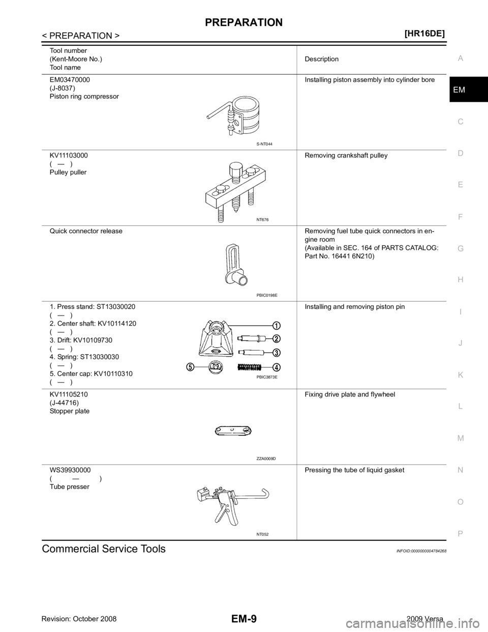
Commercial Service Tools INFOID:0000000004784268
EM03470000
(J-8037)
Piston ring compressor Installing piston assembly into cylinder bore
KV11103000
( — )
Pulley puller Removing crankshaft pulley
Quick connector release Removing fuel tube quick connectors in en- gine room
(Available in SEC. 164 of PARTS CATALOG:
Part No. 16441 6N210)
1. Press stand: ST13030020
( — )
2. Center shaft: KV10114120
( — )
3. Drift: KV10109730
( — )
4. Spring: ST13030030
( — )
5. Center cap: KV10110310
( — ) Installing and removing piston pin
KV11105210
(J-44716)
Stopper plate Fixing drive plate and flywheel
WS39930000
( — )
Tube presser Pressing the tube of liquid gasket
Tool number
(Kent-Moore No.)
Tool name Description PBIC0198E
PBIC3873E
ZZA0009D
NT052
Page 3012 of 4331

EM
NP
O
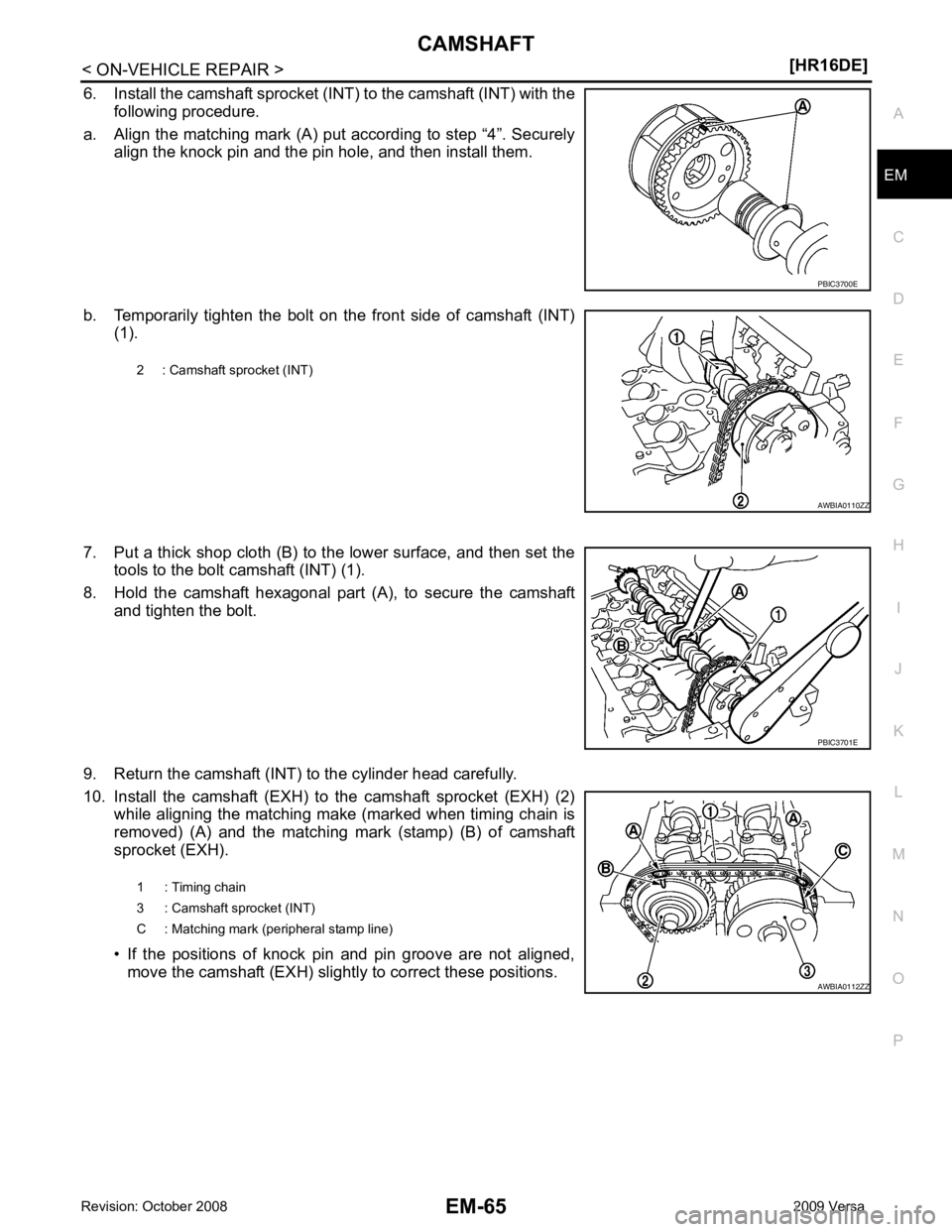
6. Install the camshaft sprocket (INT) to the camshaft (INT) with the
following procedure.
a. Align the matching mark (A) put according to step “4”. Securely align the knock pin and the pin hole, and then install them.
b. Temporarily tighten the bolt on the front side of camshaft (INT) (1).
7. Put a thick shop cloth (B) to the lower surface, and then set the tools to the bolt camshaft (INT) (1).
8. Hold the camshaft hexagonal part (A), to secure the camshaft and tighten the bolt.
9. Return the camshaft (INT) to the cylinder head carefully.
10. Install the camshaft (EXH) to the camshaft sprocket (EXH) (2) while aligning the matching make (marked when timing chain is
removed) (A) and the matching mark (stamp) (B) of camshaft
sprocket (EXH).
• If the positions of knock pin and pin groove are not aligned, move the camshaft (EXH) slightly to correct these positions. PBIC3701E
Page 3074 of 4331
![NISSAN TIIDA 2009 Service Repair Manual PRECAUTIONS
EM-127
< SERVICE INFORMATION >
[MR18DE] C
D E
F
G H
I
J
K L
M A EM
NP
O
5. When the repair work is completed, return the ignition switch to the
″LOCK ″ position before c NISSAN TIIDA 2009 Service Repair Manual PRECAUTIONS
EM-127
< SERVICE INFORMATION >
[MR18DE] C
D E
F
G H
I
J
K L
M A EM
NP
O
5. When the repair work is completed, return the ignition switch to the
″LOCK ″ position before c](/manual-img/5/57398/w960_57398-3073.png)
PRECAUTIONS
EM-127
< SERVICE INFORMATION >
[MR18DE] C
D E
F
G H
I
J
K L
M A EM
NP
O
5. When the repair work is completed, return the ignition switch to the
″LOCK ″ position before connecting
the battery cables. (At this time, the steering lock mechanism will engage.)
6. Perform a self-diagnosis check of al l control units using CONSULT-III.
Precaution for Procedur e without Cowl Top Cover INFOID:0000000004307110
When performing the procedure after removing cowl top cover, cover
the lower end of windshield.
Precaution for Drain Coolant INFOID:0000000004307112
• Drain coolant when engine is cooled.
Precaution for Disco nnecting Fuel Piping INFOID:0000000004307113
• Before starting work, make sure no fire or spark producing items are in the work area.
• Release fuel pressure before disassembly.
• After disconnecting pipes, plug openings to stop fuel leakage.
Precaution for Removal and Disassembly INFOID:0000000004307114
• When instructed to use special service tools, use the spec ified tools. Always be careful to work safely, avoid
forceful or uninstructed operations.
• Exercise maximum care to avoid damage to mating or sliding surfaces.
• Cover openings of engine system with tape or the equiva lent, if necessary, to seal out foreign materials.
• Mark and arrange disassembly parts in an organized way for easy troubleshooting and assembly.
• When loosening nuts and bolts, as a basic rule, start with the one furthest outside, then the one diagonally opposite, and so on. If the order of loosening is specif ied, do exactly as specified. Power tools may be used
where noted in the step.
Precaution for Inspection, Repair and Replacement INFOID:0000000004307115
• Before repairing or replacing, thoroughly inspect parts. Inspect new replacement parts in the same way, and
replace if necessary.
Precaution for Assembly and Installation INFOID:0000000004307116
• Use torque wrench to tighten bolts or nuts to specification.
• When tightening nuts and bolts, as a basic rule, equally tighten in several different steps starting with the ones in center, then ones on inside and outside diagonally in this order. If the order of tightening is specified,
do exactly as specified.
• Replace with new gasket, packing, oil seal or O-ring.
• Thoroughly wash, clean, and air-blow each part. Carefully check oil or coolant passages for any restriction
and blockage.
• Avoid damaging sliding or mating surfaces. Completely remove foreign materials such as cloth lint or dust. Before assembly, oil sliding surfaces well.
• Release air within route after draining coolant.
• Before starting engine, apply fuel pressure to fuel lines with turning ignition switch ON (with engine stopped). Then make sure that there are no leaks at fuel line connections.
• After repairing, start engine and increase engine speed to check coolant, fuel, oil, and exhaust systems for leakage. PIIB3706J
Page 3077 of 4331
![NISSAN TIIDA 2009 Service Repair Manual EM-130< SERVICE INFORMATION >
[MR18DE]
PREPARATION
PREPARATION
Special Service Tool INFOID:0000000004307119
The actual shapes of Kent-Moore tool s may differ from those of special service tools illust NISSAN TIIDA 2009 Service Repair Manual EM-130< SERVICE INFORMATION >
[MR18DE]
PREPARATION
PREPARATION
Special Service Tool INFOID:0000000004307119
The actual shapes of Kent-Moore tool s may differ from those of special service tools illust](/manual-img/5/57398/w960_57398-3076.png)
EM-130< SERVICE INFORMATION >
[MR18DE]
PREPARATION
PREPARATION
Special Service Tool INFOID:0000000004307119
The actual shapes of Kent-Moore tool s may differ from those of special service tools illustrated here.
Tool number
(Kent-Moore No.)
Tool name Description
KV10111100
(J-37228)
Seal cutter Removing steel oil pan and rear timing
chain case
KV10112100
(BT-8653-A)
Angle wrench Tightening bolts for bearing cap, cylinder
head, etc.
KV10107902
(J-38959)
Valve oil seal puller Removing valve oil seal
EM03470000
(J-8037)
Piston ring compressor Installing piston assembly into cylinder
bore
KV101092S0
(J-26336-B)
Valve spring compressor
1. KV10109210
(J-26336-B and J-26336-20)
Compressor
2. KV10109220
( — )
Adapter (M10)
3. KV10109230
( — )
Adapter (M8) Disassembling and assembling valve
mechanism
WS39930000
( — )
Tube presser Pressing the tube of liquid gasketNT046
NT014
S-NT011
NT044
NT718
NT052
Page 3138 of 4331
![NISSAN TIIDA 2009 Service Repair Manual CYLINDER HEAD
EM-191
< SERVICE INFORMATION >
[MR18DE] C
D E
F
G H
I
J
K L
M A EM
NP
O
Measure the diameter of valv
e stem with a micrometer (A).
Valve Guide Inner Diameter Measure the inner diameter o NISSAN TIIDA 2009 Service Repair Manual CYLINDER HEAD
EM-191
< SERVICE INFORMATION >
[MR18DE] C
D E
F
G H
I
J
K L
M A EM
NP
O
Measure the diameter of valv
e stem with a micrometer (A).
Valve Guide Inner Diameter Measure the inner diameter o](/manual-img/5/57398/w960_57398-3137.png)
CYLINDER HEAD
EM-191
< SERVICE INFORMATION >
[MR18DE] C
D E
F
G H
I
J
K L
M A EM
NP
O
Measure the diameter of valv
e stem with a micrometer (A).
Valve Guide Inner Diameter Measure the inner diameter of valve guide with a bore gauge.
Valve Guide Clearance (Valve guide clearance) = (Valve guide inner diameter) – (Valve stem diameter).
• If it exceeds the limit, replace valve guide and/or valve.
VALVE GUIDE REPLACEMENT When valve guide is removed, replace with oversized [0.2 mm (0.008 in)] valve guide.
1. To remove valve guide, heat cylinder head to 110 ° to 130 °C
(230 ° to 266 °F) by soaking in heated oil (A).
2. Drive out valve guide using suitable tools. WARNING:
Cylinder head contai ns heat, when workin g, wear protective
equipment to avoid getting burned. Standard
Intake : 5.465 - 5.480 mm (0.2152 - 0.2157 in)
Exhaust : 5.455 - 5.470 mm (0.2148 - 0.2154 in) PBIC3213J
Standard
: 5.500 - 5.518 mm (0.2165 - 0.2172 in)
Valve guide clearance:
Standard Intake : 0.020 - 0.053 mm (0.0008 - 0.0021 in)
Exhaust : 0.030 - 0.063 mm (0.0012 - 0.0025 in)
Limit : 0.1 mm (0.004 in) PBIC3214J
SEM931C
Page 3144 of 4331

EM
NP
O
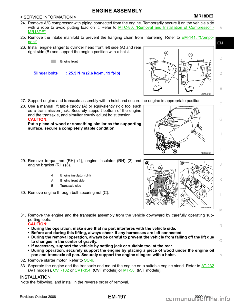
24. Remove A/C compressor with piping connected from t
he engine. Temporarily secure it on the vehicle side
with a rope to avoid putting load on it. Refer to MTC-80, " Removal and Installation of Compressor -
MR18DE " .
25. Remove the intake manifold to prevent the hanging chain from interfering. Refer to EM-141, " Compo-
nent " .
26. Install engine slinger to cylinder head front left side (A) and rear right side (B) and support the engine position with a hoist.
27. Support engine and transaxle assembly with a hoist and secure the engine in appropriate position.
28. Use a manual lift table caddy (A) or equivalently rigid tool such as a transmission jack. Securely support bottom of the engine
and the transaxle, and simultaneously adjust hoist tension.
CAUTION:
Put a piece of wood or someth ing similar as the supporting
surface, secure a completely stable condition.
29. Remove torque rod (RH) (1), engine insulator (RH) (2) and engine bracket (RH) (3).
30. Remove engine through bolt-securing nut (C).
31. Remove the engine and the transaxle assembly from the vehicle downward by carefully operating sup- porting tools.
CAUTION:
• During the operation, make sure that no part interferes with the vehicle side.
• Before and during this lifting, alw ays check if any harnesses are left connected.
• During the removal operation, alw ays be careful to prevent the vehicle from falling off the lift due
to changes in the center of gravity.
• If necessary, support the vehicle by setting jack or suitable tool at the rear.
• During operation, securely suppor t the engine by placing a piece of wood under the engine oil
pan and transaxle oil pan. Securely sup port the engine slingers with a hoist.
32. Remove starter motor. Refer to SC-9 .
33. Separate the engine and the transaxle and mount the engine on a suitable engine stand. Refer to AT-232(A/T models),
CVT-182 or
CVT-354 (CVT models) or
MT-58 (M/T models).
INSTALLATION Note the following, and install in the reverse order of removal. : Engine front
Slinger bolts : 25.5 N·m (2.6 kg-m, 19 ft-lb) PBIC3223J
Page 3189 of 4331

EX
NP
O
ON-VEHICLE REPAIR
EXHAUST SYSTEM
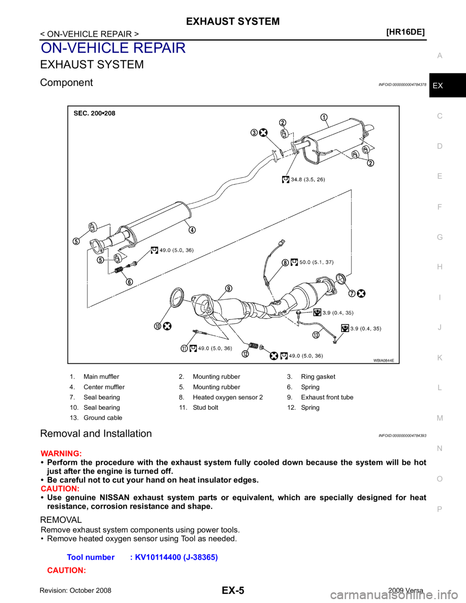
Component INFOID:0000000004784378
Removal and Installation INFOID:0000000004784393
WARNING:
• Perform the procedure with the exhaust system fu lly cooled down because the system will be hot
just after the engine is turned off.
• Be careful not to cut your hand on heat insulator edges.
CAUTION:
• Use genuine NISSAN exhaust system parts or equi valent, which are specially designed for heat
resistance, corrosion resistance and shape.
REMOVAL Remove exhaust system components using power tools.
• Remove heated oxygen sensor using Tool as needed.
CAUTION: 1. Main muffler 2. Mounting rubber 3. Ring gasket
4. Center muffler 5. Mounting rubber 6. Spring
7. Seal bearing 8. Heated oxygen sensor 2 9. Exhaust front tube
10. Seal bearing 11. Stud bolt 12. Spring
13. Ground cable