2009 NISSAN TIIDA Tools
[x] Cancel search: ToolsPage 3191 of 4331
EX
NP
O
SERVICE INFORMATION
PRECAUTIONS
Precaution for Supplemental Restraint System (SRS) "AIR BAG" and "SEAT BELT
PRE-TENSIONER" INFOID:0000000004784390
The Supplemental Restraint System such as “A IR BAG” and “SEAT BELT PRE-TENSIONER”, used along
with a front seat belt, helps to reduce the risk or severi ty of injury to the driver and front passenger for certain
types of collision. This system includes seat belt switch inputs and dual stage front air bag modules. The SRS
system uses the seat belt switches to determine the front air bag deployment, and may only deploy one front
air bag, depending on the severity of a collision and w hether the front occupants are belted or unbelted.
Information necessary to service the system safely is included in the SRS and SB section of this Service Man-
ual.
WARNING:
• To avoid rendering the SRS inoper ative, which could increase the risk of personal injury or death in
the event of a collision which would result in air bag inflation, all maintenance must be performed by
an authorized NISSAN/INFINITI dealer.
• Improper maintenance, including in correct removal and installation of the SRS can lead to personal
injury caused by unintentional act ivation of the system. For removal of Spiral Cable and Air Bag
Module, see the SRS section.
• Do not use electrical test equipm ent on any circuit related to the SRS unless instructed to in this
Service Manual. SRS wiring harnesses can be identi fied by yellow and/or orange harnesses or har-
ness connectors.
• When working near the Airbag Diagnosis Sensor Un it or other Airbag System sensors with the Igni-
tion ON or engine running, DO NOT use air or el ectric power tools or strike near the sensor(s) with a
hammer. Heavy vibration could activate the sensor( s) and deploy the air bag(s), possibly causing
serious injury.
• When using air or electric power tools or hammers , always switch the Ignition OFF, disconnect the
battery, and wait at least 3 minutes before performing any service.
Precaution Necessary for Steering Wh eel Rotation After Battery Disconnect
INFOID:0000000004675325
NOTE:
• This Procedure is applied only to models with Inte lligent Key system and NATS (NISSAN ANTI-THEFT SYS-
TEM).
• Remove and install all control units after disconnecti ng both battery cables with the ignition knob in the
″ LOCK ″ position.
• Always use CONSULT-III to perform self-diagnosis as a part of each function inspection after finishing work.
If DTC is detected, perform trouble diagnosis according to self-diagnostic results.
For models equipped with the Intelligent Key system and NATS , an electrically controlled steering lock mech-
anism is adopted on the key cylinder.
For this reason, if the battery is disconnected or if the battery is discharged, the steering wheel will lock and
steering wheel rotation will become impossible.
If steering wheel rotation is required when battery pow er is interrupted, follow the procedure below before
starting the repair operation.
OPERATION PROCEDURE 1. Connect both battery cables. NOTE:
Supply power using jumper cables if battery is discharged.
2. Use the Intelligent Key or mechanical key to turn the ignition switch to the ″ACC ″ position. At this time, the
steering lock will be released.
3. Disconnect both battery cables. The steering lock will remain released and the steering wheel can be
rotated.
4. Perform the necessary repair operation.
5. When the repair work is completed, return the ignition switch to the ″LOCK ″ position before connecting
the battery cables. (At this time, the steering lock mechanism will engage.)
6. Perform a self-diagnosis check of al l control units using CONSULT-III.
Page 3194 of 4331
![NISSAN TIIDA 2009 Service Repair Manual EX-10< SERVICE INFORMATION >
[MR18DE]
EXHAUST SYSTEM
• Be careful not to cut your ha nd on heat insulator edges.
CAUTION:
• Use genuine NISSAN exhaust system parts or equi valent, which a NISSAN TIIDA 2009 Service Repair Manual EX-10< SERVICE INFORMATION >
[MR18DE]
EXHAUST SYSTEM
• Be careful not to cut your ha nd on heat insulator edges.
CAUTION:
• Use genuine NISSAN exhaust system parts or equi valent, which a](/manual-img/5/57398/w960_57398-3193.png)
EX-10< SERVICE INFORMATION >
[MR18DE]
EXHAUST SYSTEM
• Be careful not to cut your ha nd on heat insulator edges.
CAUTION:
• Use genuine NISSAN exhaust system parts or equi valent, which are specially designed for heat
resistance, corrosion resistance and shape.
REMOVAL
Remove exhaust system components using power tools.
• Remove heated oxygen sensor using Tool as needed.
CAUTION:
Be careful not to damage heated oxygen sensor.
INSTALLATION
Installation is in the reverse order of removal.
CAUTION:
• Always replace exhaust gaskets and seal bear ings with new ones when installing.
• Before installing a new heated oxygen sensor, clean and apply an ti-seize lubricant to exhaust sys-
tem threads using suitable tool.
• Discard any heated oxygen sensor which has been dropped from a height of more than 0.5 m (19.7
in) onto a hard surface such as a co ncrete floor; install a new one.
• Do not over-tighten the heated oxygen sensor. Doing so may damage the heated oxygen sensor,
resulting in the MIL coming on.
• Remove deposits from the sealing surface of each connection. Connect them securely to avoid
exhaust leakage.
• Temporarily tighten nuts on the exhaust manifold side and bolts on the vehicle side. Check each part
for unusual interference, and then ti ghten them to the specified torque.
• When installing each mounting rubb er, avoid twisting or unusual extension in up/down and right/left
directions.
Exhaust Manifold to Exhaust Front Tube
1. Securely insert seal bearing (2) into exhaust manifold (1) side in the direction shown.
• Exhaust front tube (5)
CAUTION:
Be careful not to damage seal bearing surface when install-
ing.
2. Install spring (3), tighten nut (4). • Be careful that the stud bolt nut does not interfere with the
flanged area ( ).
• Make sure the spring (3) sits properly on the flange surface by aligning it to the locator dimples.
Exhaust Front Tube to Center Muffler
1. Securely insert seal bearing (2) into exhaust front tube (1) side in the direction shown.
• Center muffler (5)
CAUTION:
Be careful not to damage seal bearing surface when install-
ing.
2. Install spring (3), tighten bolt (4). • Be careful that the stud bolt does not interfere with the flanged
area ( ).
• Make sure the spring (3) sits properly on the flange surface by
aligning it to the locator dimples.
INSPECTION AFTER INSTALLATION Tool number : KV10114400 (J-38365)
Oxygen sensor thread cleaner : — (J-43897-18)
Oxygen sensor thread cleaner : — (J-43897-12) PBIC3797E
PBIC3798E
Page 3223 of 4331
PREPARATION
FL-3
< SERVICE INFORMATION >
C
D E
F
G H
I
J
K L
M A FL
NP
O
PREPARATION
Special Service Tool INFOID:0000000004305252
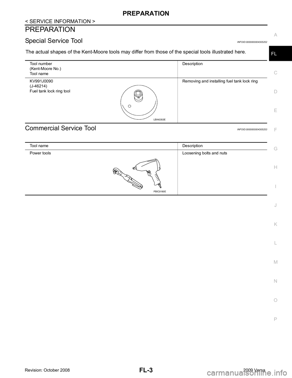
The actual shapes of the Kent-Moore tools may differ from those of the special tools illustrated here.
Commercial Service Tool INFOID:0000000004305253
Tool number
(Kent-Moore No.)
Tool name Description
KV991J0090
(J-46214)
Fuel tank lock ring tool Removing and installing fuel tank lock ring LBIA0353E
Tool name Description
Power tools Loosening bolts and nuts PBIC0190E
Page 3230 of 4331
FL-10< SERVICE INFORMATION >
FUEL TANK
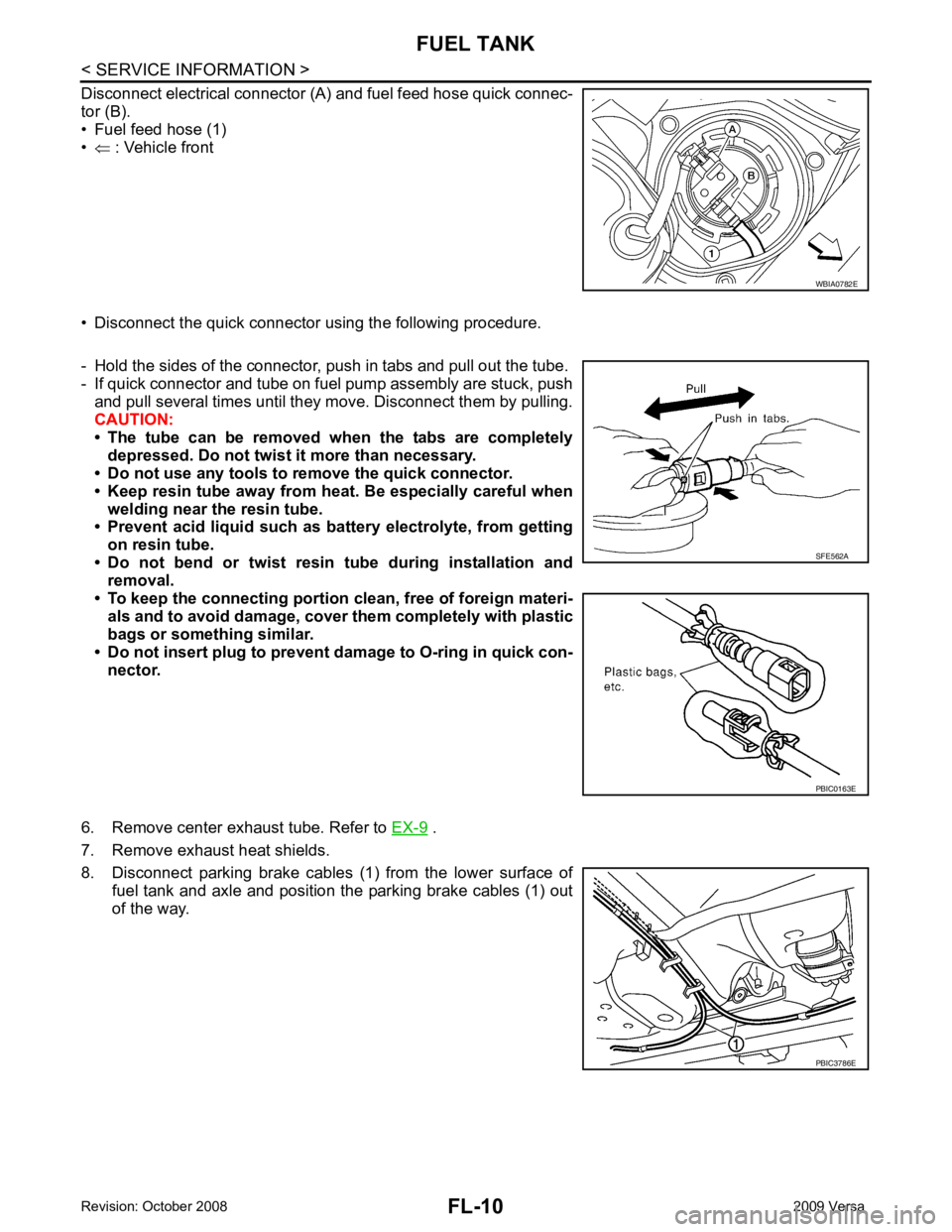
Disconnect electrical connector (A) and fuel feed hose quick connec-
tor (B).
• Fuel feed hose (1)
• ⇐ : Vehicle front
• Disconnect the quick connector using the following procedure.
- Hold the sides of the connector, push in tabs and pull out the tube.
- If quick connector and tube on fuel pump assembly are stuck, push
and pull several times until they move. Disconnect them by pulling.
CAUTION:
• The tube can be removed when the tabs are completely depressed. Do not twist it more than necessary.
• Do not use any tools to remove the quick connector.
• Keep resin tube away from h eat. Be especially careful when
welding near the resin tube.
• Prevent acid liquid such as ba ttery electrolyte, from getting
on resin tube.
• Do not bend or twist resin tube during installation and removal.
• To keep the connecting portion clean, free of foreign materi-
als and to avoid damage, cover them completely with plastic
bags or something similar.
• Do not insert plug to prevent damage to O-ring in quick con-
nector.
6. Remove center exhaust tube. Refer to EX-9 .
7. Remove exhaust heat shields.
8. Disconnect parking brake cables (1) from the lower surface of
fuel tank and axle and position the parking brake cables (1) out
of the way. WBIA0782E
SFE562A
PBIC0163E
PBIC3786E
Page 3231 of 4331
FL
NP
O
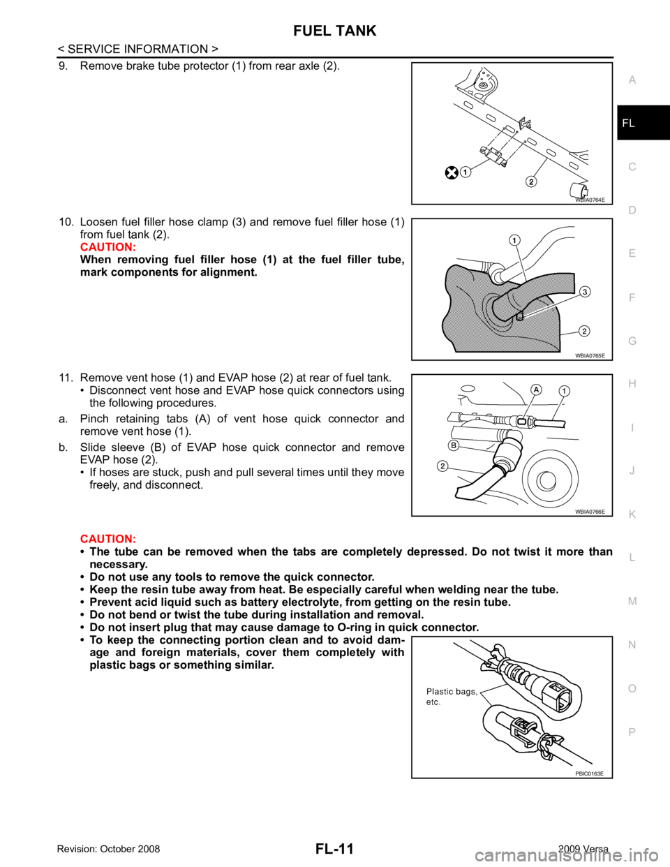
9. Remove brake tube protector (1) from rear axle (2).
10. Loosen fuel filler hose clamp (3) and remove fuel filler hose (1) from fuel tank (2).
CAUTION:
When removing fuel filler hose (1) at the fuel filler tube,
mark components for alignment.
11. Remove vent hose (1) and EVAP hose (2) at rear of fuel tank. • Disconnect vent hose and EVAP hose quick connectors usingthe following procedures.
a. Pinch retaining tabs (A) of vent hose quick connector and remove vent hose (1).
b. Slide sleeve (B) of EVAP hose quick connector and remove EVAP hose (2).
• If hoses are stuck, push and pull several times until they move freely, and disconnect.
CAUTION:
• The tube can be removed when the tabs are completely depressed. Do not twist it more than
necessary.
• Do not use any tools to remove the quick connector.
• Keep the resin tube away from heat. Be especi ally careful when welding near the tube.
• Prevent acid liquid such as battery elect rolyte, from getting on the resin tube.
• Do not bend or twist the tube during installation and removal.
• Do not insert plug that may cause dama ge to O-ring in quick connector.
• To keep the connecting portio n clean and to avoid dam-
age and foreign materials, cover them completely with
plastic bags or something similar. WBIA0765E
WBIA0766E
Page 3237 of 4331
PRECAUTIONS
FSU-3
< SERVICE INFORMATION >
C
D
F
G H
I
J
K L
M A
B FSU
N
O P
5. When the repair work is completed, return the ignition switch to the
″LOCK ″ position before connecting
the battery cables. (At this time, the steering lock mechanism will engage.)
6. Perform a self-diagnosis check of al l control units using CONSULT-III.
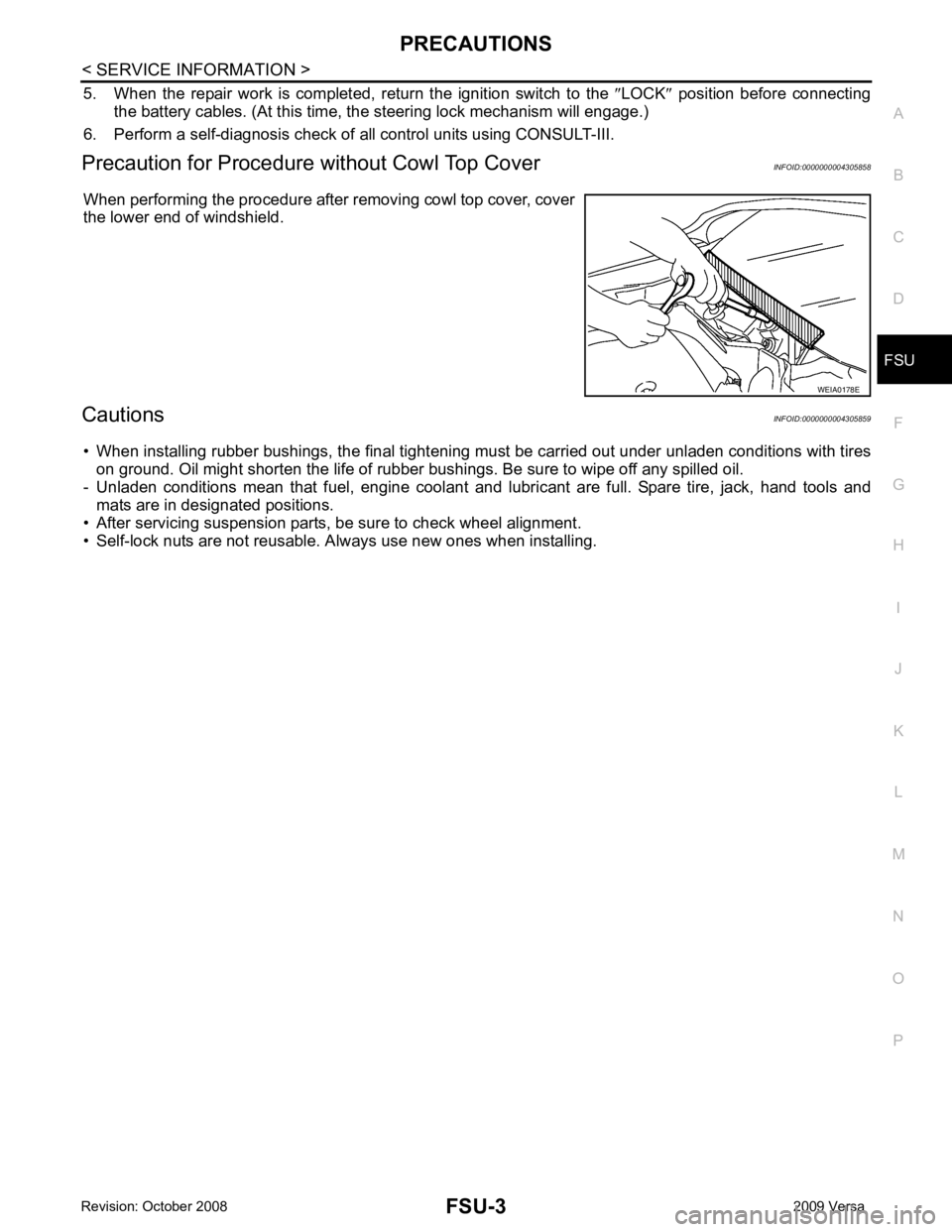
Precaution for Procedur e without Cowl Top Cover INFOID:0000000004305858
When performing the procedure after removing cowl top cover, cover
the lower end of windshield.
Cautions INFOID:0000000004305859
• When installing rubber bushings, the final tightening mu st be carried out under unladen conditions with tires
on ground. Oil might shorten the life of rubber bushings. Be sure to wipe off any spilled oil.
- Unladen conditions mean that fuel, engine coolant and l ubricant are full. Spare tire, jack, hand tools and
mats are in designated positions.
• After servicing suspension parts, be sure to check wheel alignment.
• Self-lock nuts are not reusable. A lways use new ones when installing. WEIA0178E
Page 3241 of 4331
FSU
N
O P
FRONT SUSPENSION ASSEMBLY
On-Vehicle Inspection and Service INFOID:0000000004305863
Make sure the mounting conditions (looseness, back lash) of each component and component conditions
(wear, damage) are normal.
INSPECTION OF LOWER BALL JOINT END PLAY 1. Set front wheels in a straight-ahead position. Do not depress brake pedal.
2. Place an iron bar or similar tool bet ween transverse link and steering knuckle.
3. Measure axial end play by prying it up and down.
CAUTION:
Be careful not to damage ball joint boot. Do not damage the installation position by applying
excessive force.
STRUT INSPECTION Check for oil leakage, damage and replace as necessary.
Wheel Alignment Inspection INFOID:0000000004305864
PRELIMINARY INSPECTION WARNING:
Always adjust the alignment with the vehicle on a flat surface.
NOTE:
If alignment is out of specification, inspect and r eplace any damaged or worn rear suspension parts before
making any adjustments.
1. Check and adjust the wheel alignment with the vehicle under unladen conditions. “Unladen conditions”
means that the fuel, coolant, and lubricant are full; and that the spare tire, jack, hand tools and mats are in
their designated positions.
2. Check the tires for incorrect air pressure and excessive wear.
3. Check the wheels for run out and damage. Refer to WT-6, " Inspection " .
4. Check the wheel bearing axial end play. Refer to FAX-6, " On-Vehicle Inspection and Service " .
5. Check the shock absorbers for leaks or damage.
6. Check each mounting point of the suspension components for any excessive looseness or damage.
7. Check each link, arm, and the suspension member for any damage.
8. Check the vehicle height. Refer to FSU-19, " Wheelarch Height (Unladen*) " .
GENERAL INFORMATION AND RECOMMENDATIONS 1. A Four-Wheel Thrust Alignment should be performed. • This type of alignment is re commended for any NISSAN vehicle.
• The four-wheel “thrust” process helps ensure that the vehicle is properly aligned and the steering wheel
is centered.
• The alignment machine itself should be ca pable of accepting any NISSAN vehicle.
• The alignment machine should be checked to ensure that it is level.
2. Make sure the alignment machine is properly calibrated. • Your alignment machine should be regularly calib rated in order to give correct information.
• Check with the manufacturer of your specific a lignment machine for their recommended Service/Cali-
bration Schedule.
THE ALIGNMENT PROCESS IMPORTANT: Use only the alignment specifications listed in this Service Manual. Refer to FSU-17, " Wheel
Alignment (Unladen*) " .
1. When displaying the alignment settings, many alignm ent machines use “indicators”: (Green/red, plus or
minus, Go/No Go). Do NOT use these indicators.
• The alignment specifications programmed into your alignment machine that operate these indicators
may not be correct. Axial end play : 0 mm (0 in)
Page 3251 of 4331
SERVICE DATA AND SPECIFICATIONS (SDS)
FSU-17
< SERVICE INFORMATION >
C
D
F
G H
I
J
K L
M A
B FSU
N
O P
SERVICE DATA AND SPECIFICATIONS (SDS)
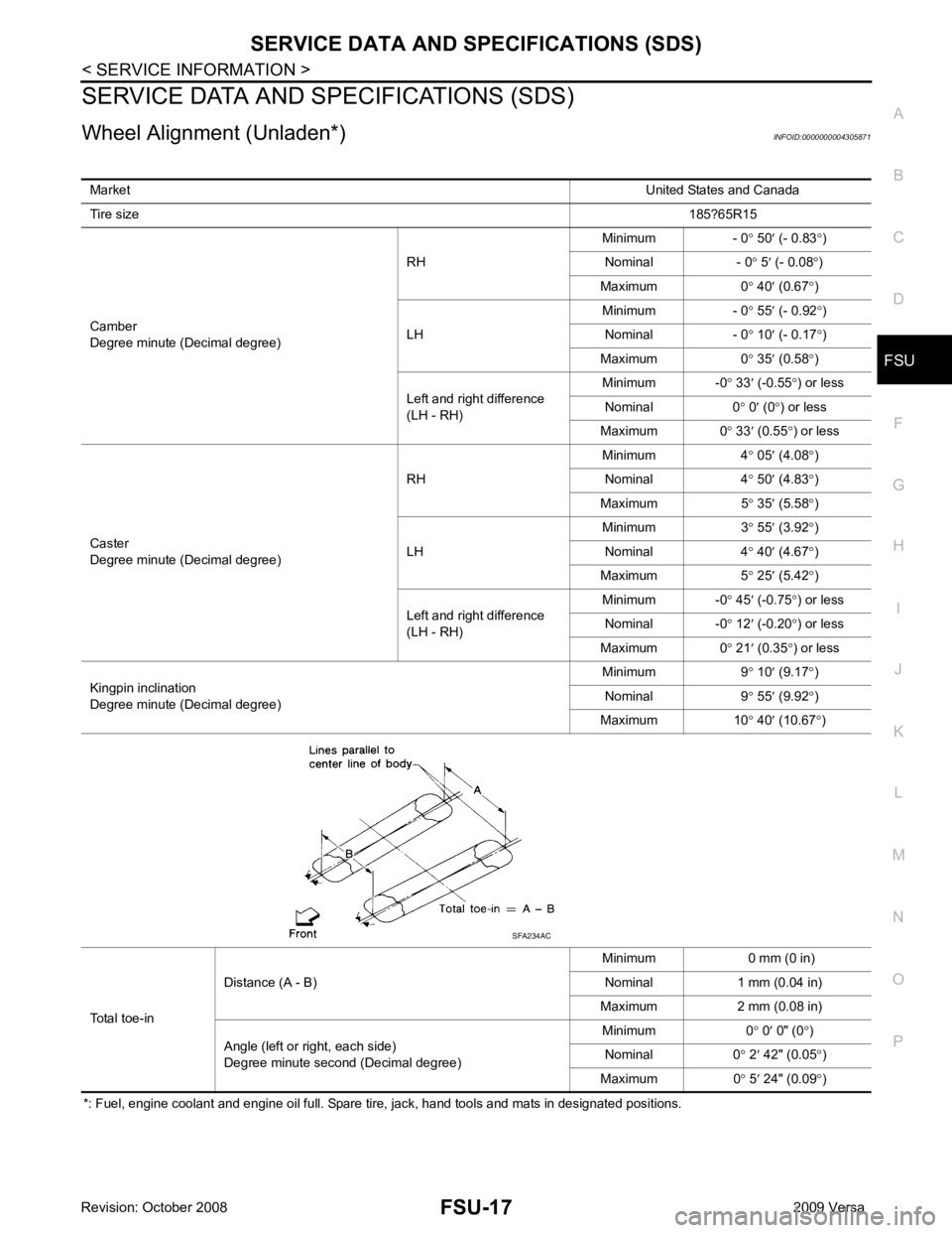
Wheel Alignment (Unladen*) INFOID:0000000004305871
*: Fuel, engine coolant and engine oil full. Spare tire, jack, hand tools and mats in designated positions. Market
United States and Canada
Tire size 185?65R15
Camber
Degree minute (Decimal degree) RH
Minimum - 0
° 50 ′ (- 0.83 °)
Nominal - 0 ° 5 ′ (- 0.08 °)
Maximum 0 ° 40 ′ (0.67 °)
LH Minimum - 0
° 55 ′ (- 0.92 °)
Nominal - 0 ° 10 ′ (- 0.17 °)
Maximum 0 ° 35 ′ (0.58 °)
Left and right difference
(LH - RH) Minimum -0
° 33 ′ (-0.55 °) or less
Nominal 0 ° 0 ′ (0 °) or less
Maximum 0 ° 33 ′ (0.55 °) or less
Caster
Degree minute (Decimal degree) RH
Minimum 4
° 05 ′ (4.08 °)
Nominal 4 ° 50 ′ (4.83 °)
Maximum 5 ° 35 ′ (5.58 °)
LH Minimum 3
°
55 ′ (3.92 °)
Nominal 4 ° 40 ′ (4.67 °)
Maximum 5 ° 25 ′ (5.42 °)
Left and right difference
(LH - RH) Minimum -0
° 45 ′ (-0.75 °) or less
Nominal -0 ° 12 ′ (-0.20 °) or less
Maximum 0 ° 21 ′ (0.35 °) or less
Kingpin inclination
Degree minute (Decimal degree) Minimum 9
° 10 ′ (9.17 °)
Nominal 9 ° 55 ′ (9.92 °)
Maximum 10 ° 40 ′ (10.67 °)
Total toe-in Distance (A - B)
Minimum 0 mm (0 in)
Nominal 1 mm (0.04 in)
Maximum 2 mm (0.08 in)
Angle (left or right, each side)
Degree minute second (Decimal degree) Minimum 0
° 0 ′ 0" (0 °)
Nominal 0 ° 2 ′ 42" (0.05 °)
Maximum 0 ° 5 ′ 24" (0.09 °) SFA234AC