Page 352 of 4331

ASSEMBLY
AT-347
< SERVICE INFORMATION >
D
E
F
G H
I
J
K L
M A
B AT
N
O P
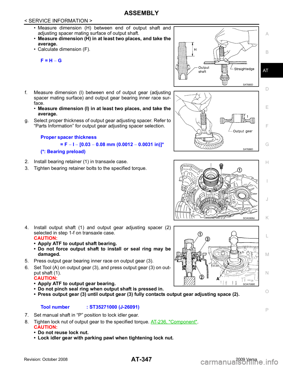
• Measure dimension (H) between end of output shaft and
adjusting spacer mating surface of output shaft.
• Measure dimension (H) in at least two places, and take the
average.
• Calculate dimension (F).
f. Measure dimension (I) betw een end of output gear (adjusting
spacer mating surface) and output gear bearing inner race sur-
face.
• Measure dimension (I) in at least two places, and take the
average.
g. Select proper thickness of output gear adjusting spacer. Refer to “Parts Information” for output gear adjusting spacer selection.
2. Install bearing retainer (1) in transaxle case.
3. Tighten bearing retainer bolts to the specified torque.
4. Install output shaft (1) and output gear adjusting spacer (2) selected in step 1-f on transaxle case.
CAUTION:
• Apply ATF to output shaft bearing.
• Do not force output shaft to install or seal ring may be
damaged.
5. Press output gear bearing inner race on output gear (3).
6. Set Tool (A) on output gear (3), and press output gear (3) on out- put shaft (1).
CAUTION:
• Apply ATF to output gear bearing.
• Do not pinch seal ring when output shaft is pressed in.
• Press output gear (3) until output gear (3 ) fully contacts output gear adjusting space (2).
7. Set manual shaft in “P” position to lock idler gear.
8. Tighten lock nut of output gear to the specified torque. AT-236, " Component " .
CAUTION:
• Do not reuse lock nut.
• Lock idler gear with parking pawl when tightening lock nut. F = H
− G SAT685D
Proper spacer thickness
= F − I − [0.03 − 0.08 mm (0.0012 − 0.0031 in)]*
(*: Bearing preload) SAT686D
SCIA5909J
Tool number : ST35271000 (J-26091) SCIA7080E
Page 353 of 4331
Component " .
13. After properly adjusting turning torque, clinch lock nuts (1) of idler gear and output gear as shown.
14. Install side cover gasket and side cover on transaxle case. CAUTION:
• Do not reuse side cover gasket.
• Completely remove all moisture, oil and old gasket, etc. from the transaxle case and side cover mating surfaces.
15. Tighten side cover bolts (1) to the specified torque. Refer to AT-236, " Component " .
Adjustment (1) (For MR18DE Engine Models) INFOID:0000000004305529
DIFFERENTIAL SIDE BEARING PRELOAD
1. Select proper thickness of differential side bearing adjusting shim using the following procedures. Tool number : ST27180001 (J-25726-A)
Output Shaft " .
SCIA6039J
Page 356 of 4331

ASSEMBLY
AT-351
< SERVICE INFORMATION >
D
E
F
G H
I
J
K L
M A
B AT
N
O P
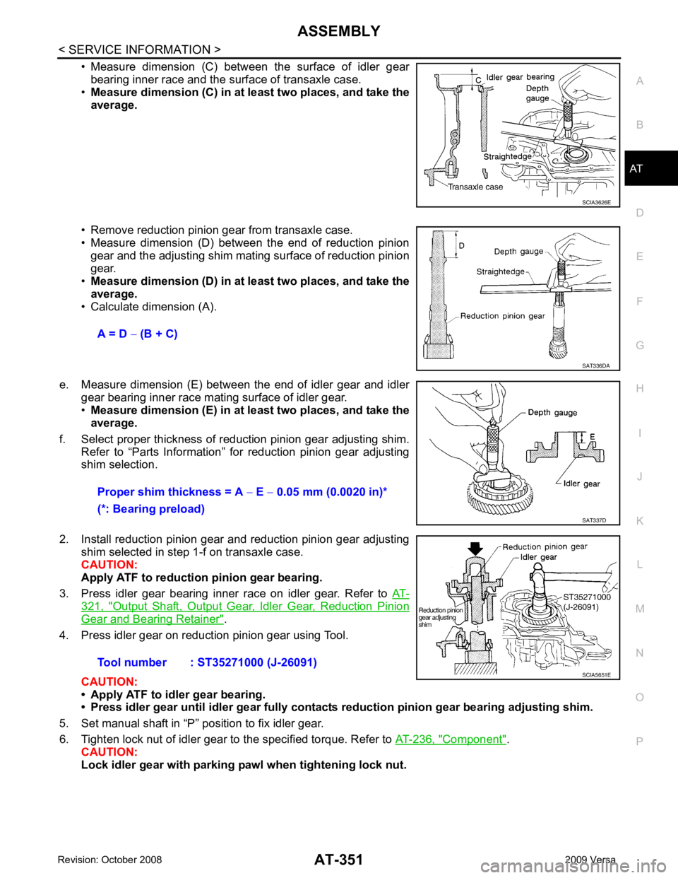
• Measure dimension (C) between the surface of idler gear
bearing inner race and the surface of transaxle case.
• Measure dimension (C) in at least two places, and take the
average.
• Remove reduction pinion gear from transaxle case.
• Measure dimension (D) between the end of reduction pinion gear and the adjusting shim mating surface of reduction pinion
gear.
• Measure dimension (D) in at least two places, and take the
average.
• Calculate dimension (A).
e. Measure dimension (E) between the end of idler gear and idler gear bearing inner race mating surface of idler gear.
• Measure dimension (E) in at least two places, and take the
average.
f. Select proper thickness of reduction pinion gear adjusting shim. Refer to “Parts Information” for reduction pinion gear adjusting
shim selection.
2. Install reduction pinion gear and reduction pinion gear adjusting shim selected in step 1-f on transaxle case.
CAUTION:
Apply ATF to reduction pinion gear bearing.
3. Press idler gear bearing inner race on idler gear. Refer to AT-321, " Output Shaft, Output Gear, Idler Gear, Reduction Pinion
Gear and Bearing Retainer " .
4. Press idler gear on reduction pinion gear using Tool.
CAUTION:
• Apply ATF to idler gear bearing.
• Press idler gear until idler gear fully contacts reduction pinion gear bearing adjusting shim.
5. Set manual shaft in “P” position to fix idler gear.
6. Tighten lock nut of idler gear to the specified torque. Refer to AT-236, " Component " .
CAUTION:
Lock idler gear with parking pa wl when tightening lock nut. SCIA3626E
A = D
− (B + C) SAT336DA
Proper shim thickness = A
− E − 0.05 mm (0.0020 in)*
(*: Bearing preload) SAT337D
Tool number : ST35271000 (J-26091)
SCIA5651E
Page 357 of 4331
AT-352< SERVICE INFORMATION >
ASSEMBLY
7. Measure turning torque of reduction pinion gear using Tool.
•When measuring turning torq ue, turn reduction pinion
gear in both directions several times to seat bearing roll-
ers correctly.
• If turning torque is out of specification, decrease or
increase thickness of reducti on pinion gear adjusting
shim.
8. After properly adjusting turning torque, clinch idler gear lock nut as shown.
CAUTION:
Do not reuse idler gear lock nut.
OUTPUT SHAFT END PLAY
1. Select proper thickness of output shaft adjusting shim using the following procedures.
a. Install bearing retainer (1) in transaxle case. Refer to AT-321," Output Shaft, Output Gear, Idler Gear, Reduction Pinion Gear
and Bearing Retainer " .
Tool number : ST3127S000 (J-25765-A)
Turning torque of reduction pinion gear: Refer to AT-377, " Reduction Pinion Gear " .
SCIA5514E
SCIA4915E
SCIA8013E
SCIA5909J
Page 360 of 4331
ASSEMBLY
AT-355
< SERVICE INFORMATION >
D
E
F
G H
I
J
K L
M A
B AT
N
O P
3. Install forward clutch assembly and overrun clutch assembly (1)
into transaxle case.
CAUTION:
• Align teeth of low & r everse brake drive plates before
installing.
• Make sure that bearing retain er seal rings are not spread.
4. Install needle bearing (1) on bearing retainer. CAUTION:
Be careful with the dir ection of needle bearing.
5. Install thrust washer (1) on overrun clutch hub (2). CAUTION:
Align pawls of thrust washer (1) with holes of overrun
clutch hub (2).
6. Install overrun clutch hub (1) into forward clutch drum. CAUTION:
Align teeth of overrun clutch drive plates before installing.
7. Hold forward clutch hub, and check that rear internal gear locks when tried to rotate counterclockwise.
CAUTION:
If rear internal gear rotates counterclockwise, check instal-
lation direction of fo rward one-way clutch. SCIA5900J
SCIA8014E
SCIA5899J
SCIA5898J
SCIA7078E
Page 362 of 4331
ASSEMBLY
AT-357
< SERVICE INFORMATION >
D
E
F
G H
I
J
K L
M A
B AT
N
O P
13. Install needle bearing (1) on front planetary carrier (2).
CAUTION:
Be careful with the direct ion of needle bearing (1).
14. Install low one-way clutch to front planetary carrier by turning it in the direction of unlock.
15. Check that low one-way clutch rotates counterclockwise around front planetary carrier. Then try to turn it clockwise and check
that it is locked.
16. Install front planetary carrier (2) and low one-way clutch (1) as a set into transaxle case.
17. Install snap ring into transaxle case using a flat-bladed screw- driver.
18. Install needle bearing (1) on front sun gear (2). CAUTION:
Be careful with the direct ion of needle bearing (1). SCIA6047J
SAT048D
SCIA5896J
SCIA3633E
SCIA6960E
Page 368 of 4331
ASSEMBLY
AT-363
< SERVICE INFORMATION >
D
E
F
G H
I
J
K L
M A
B AT
N
O P
4. Install anchor end pin (2) and lock nut (1) on transaxle case.
5. Place brake band on outside of reverse clutch drum.
6. Tighten anchor end pin just enough so that brake band is evenly fitted on reverse clutch drum.
7. Install bearing race selected in total end play adjustment step on oil pump cover.
8. Install thrust washer selected in reverse clutch end play adjust- ment step on oil pump cover.
9. Install O-ring to oil pump assembly. CAUTION:
• Do not reuse O-ring.
• Apply ATF to O-ring.
10. Install oil pump assembly (1) on transaxle case.
11. Tighten oil pump bolts to the specified torque. Refer to AT-236," Component " .
12. Install O-ring to input shaft assembly (high clutch drum). SCIA6037J
SAT038D
SCIA3629E
SCIA6036J
SCIA4928E
Page 377 of 4331

.
Vehicle Speed at Which Gear Shifting Occurs INFOID:0000000004807935
HR16DE engine models
MR18DE engine models
• At half throttle, the accelerator opening is 4/8 of the full opening.
Vehicle Speed at When Lock-up Occurs/Releases INFOID:0000000004807936
HR16DE engine models
MR18DE engine models Engine
HR16DE MR18DE
Automatic transaxle model RE4F03B
Automatic transaxle assembly Model code number 3CX3D, 3CX3E 3CX0D
Transaxle gear ratio 1st 2.861
2nd 1.562
3rd 1.000
4th 0.697
Reverse 2.310
Final drive 4.072
Recommended fluid Genuine NISSAN Matic D ATF (Conti
nental U.S. and Alaska) or
Canada NISSAN Automatic Transmission Fluid*
Fluid capacity [ (US qt, Imp qt)] 7.7 (8-1/8, 6-3/4) 7.9 (8-3/8, 7)Throttle position
Vehicle speed km/h (MPH)
D 1
→ D 2 D2 → D 3 D3 → D 4 D4 → D 3 D3 → D 2 D2 → D 1
Full throttle 49 - 57
(31 - 35) 93 - 101
(58 - 62) 148 - 156
(92 - 96) 144 - 152
(90 - 94) 82 - 90
(51 - 55) 39 - 47
(25 - 29)
Half throttle 35 - 43
(22 - 26) 59 - 67
(37 - 41) 117 - 125
(73 - 77) 59 - 67
(37 - 41) 34 - 42
(22 - 26) 15 - 23
(10 - 14)
Throttle position Vehicle speed km/h (MPH)
D 1 → D 2 D2 → D 3 D3 → D 4 D4 → D 3 D3 → D 2 D2 → D 1
Full throttle 51 - 59
(32 - 37) 97 - 105
(60 - 65) 154 - 162
(96 - 101) 150 - 158
(93 - 98) 87 - 95
(54 - 59) 40 - 48
(25 - 30)
Half throttle 34 - 42
(21 - 26) 62 - 70
(39 - 43) 124 - 132
(77 - 82) 69 - 77
(43 - 48) 36 - 44
(22 - 27) 19 - 27
(12 - 17) Throttle position Selector lever position
Vehicle speed km/h (MPH)
Lock-up ON Lock-up OFF
2.0/8 “D” position 73 - 81 (46
- 50) 49 - 57 (31 - 35)
“D” position (OD OFF) 86 - 94 (53 - 58) 82 - 90 (51 - 55)
Throttle position Selector lever position Vehicle speed km/h (MPH)
Lock-up ON Lock-up OFF
2.0/8 “D” position 86 - 94 (53
- 58) 59 - 67 (37 - 42)
“D” position (OD OFF) 86 - 94 (53 - 58) 83 - 91 (52 - 57)