Page 254 of 4331

AT
N
O P
Oil Channel
INFOID:0000000004305511
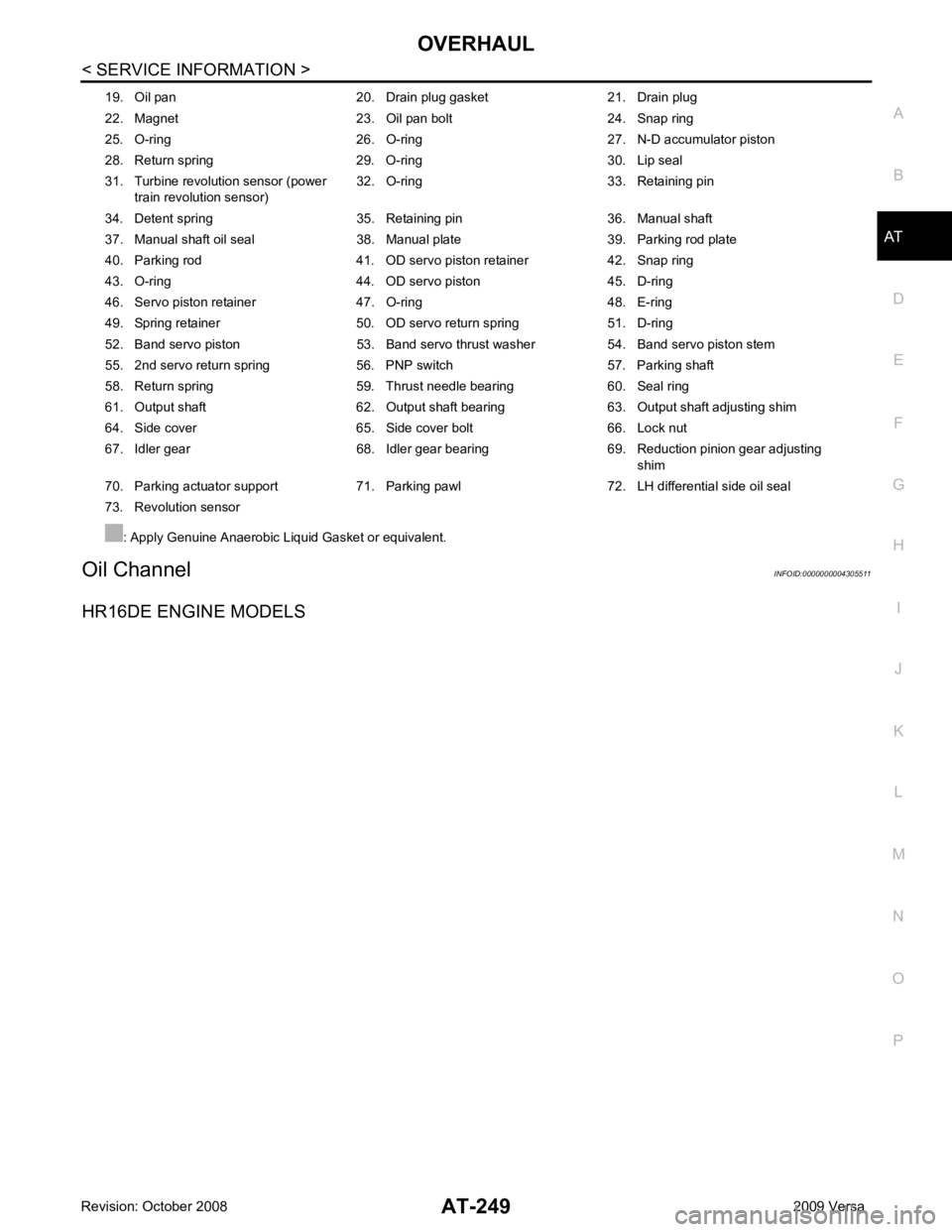
HR16DE ENGINE MODELS 19. Oil pan 20. Drain plug gasket 21. Drain plug
22. Magnet 23. Oil pan bolt 24. Snap ring
25. O-ring 26. O-ring 27. N-D accumulator piston
28. Return spring 29. O-ring 30. Lip seal
31. Turbine revolution sensor (power train revolution sensor) 32. O-ring 33. Retaining pin
34. Detent spring 35. Retaining pin 36. Manual shaft
37. Manual shaft oil seal 38. Manual plate 39. Parking rod plate
40. Parking rod 41. OD servo piston retainer 42. Snap ring
43. O-ring 44. OD servo piston 45. D-ring
46. Servo piston retainer 47. O-ring 48. E-ring
49. Spring retainer 50. OD servo return spring 51. D-ring
52. Band servo piston 53. Band servo thrust washer 54. Band servo piston stem
55. 2nd servo return spring 56. PNP switch 57. Parking shaft
58. Return spring 59. Thrust needle bearing 60. Seal ring
61. Output shaft 62. Output shaft bearing 63. Output shaft adjusting shim
64. Side cover 65. Side cover bolt 66. Lock nut
67. Idler gear 68. Idler gear bearing 69. Reduction pinion gear adjusting shim
70. Parking actuator support 71. Parking pawl 72. LH differential side oil seal
73. Revolution sensor
: Apply Genuine Anaerobic Liquid Gasket or equivalent.
Page 268 of 4331
AT
N
O P
a. Remove O-ring from input shaft assembly (high clutch drum).
b. Remove oil pump assembly bolts, and then remove oil pump assembly (1) from transaxle case.
c. Remove O-ring from oil pump assembly (1).
d. Remove bearing race (1) and thrust washer (2) from oil pump assembly (3).
30. Remove brake band according to the following procedures.
a. Loosen lock nut (1), and then remove anchor end pin (2) and lock nut (1) as a set from transaxle case.
Page 272 of 4331
AT
N
O P
c. Check that low one-way clutch rotates counter-clockwise around
front planetary carrier. Then try to turn it clockwise and check
that it is locked.
• Replace low one-way clutch if necessary.
d. Remove low one-way clutch from front planetary carrier by turn- ing it in the direction of unlock.
• Inspect low one-way clutch , and replace if damaged or
worn.
e. Remove needle bearing (1) from front planetary carrier (2). •Inspect needle bearing (1) a nd front planetary carrier (2),
and replace if damaged or worn.
f. Check clearance between pinion washer and front planetary carrier using feeler gauge.
• Replace front planetary carrier if the clearance exceeds
allowable limit.
38. Remove rear planetary carrier and rear sun gear according to the following procedures.
a. Remove rear planetary carrier (with rear sun gear) from tran- saxle case. SCIA6047J
Planetary Carrier " .
SAT051D
Page 306 of 4331
AT
N
O P
7. Measure clearance between retaining plate and snap ring using
feeler gauge. If not within allowable limit, select proper retaining
plate. Refer to “Parts Information” for retaining plate selection.
8. Check operation of reverse clutch.
High Clutch INFOID:0000000004305521
COMPONENTS
DISASSEMBLY 1. Check operation of high clutch.
a. Apply compressed air into the oil hole (A) of input shaft assem- bly (high clutch drum) at the location as shown.
CAUTION:
Block the oil hole (A) on the opposite side with lint-free
cloth (B).
b. Check to see that retaining plate moves to snap ring.
c. If retaining plate does not contact snap ring: • High clutch piston seal might be damaged.Specified clearance
Standard and allowable limit: Refer to AT-375, " Clutches and Brakes " .
Page 339 of 4331
AT-334< SERVICE INFORMATION >
REPAIR FOR COMPONENT PARTS
• Check each return spring for damage or deformation. Also mea- sure free length. Refer to AT-377, " Band Servo " .
• Replace springs if deformed or fatigued.
ASSEMBLY
1. Install D-rings to band servo piston.
2. Install band servo thrust washer (4), band servo piston (3), OD servo return spring (2) and spring retainer (1) to band servo pis-
ton stem (5).
3. Place band servo piston stem (1) on a wooden block, and install E-ring (2) to band servo piston stem (1) while pressing spring
retainer (3) downward.
4. Install O-ring to servo piston retainer. SAT138D
SCIA3688E
SCIA7054E
SCIA7056E
Page 344 of 4331
AT
N
O P
3. Remove speedometer drive gear from differential case.
4. Drive out lock pin from differential case (1) using Tool (A).
5. Draw out pinion mate shaft.
6. Remove pinion mate gears, pinion mate gear thrust washers, side gears and side gear thrust washers.
INSPECTION
Gears, Washers, Pinion Mate Shaft and Differential Case • Check mating surfaces of differential case, side gears, pinion mate gears and pinion mate shaft. Replace if necessary.
• Check washers for wear. Replace if necessary.
Bearings SAT316D
SAT544F
Page 346 of 4331

AT
N
O P
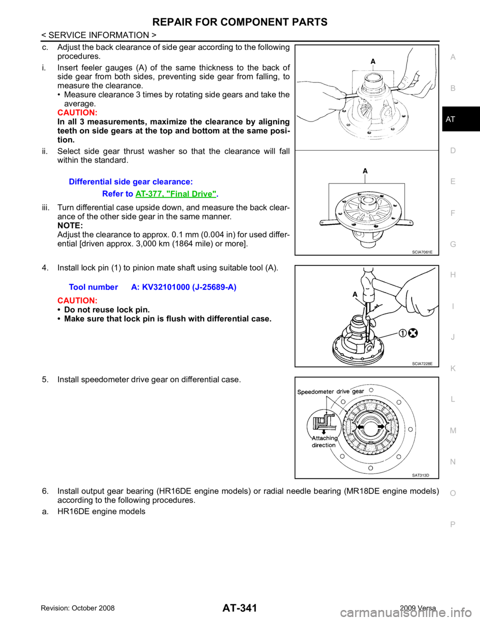
c. Adjust the back clearance of side
gear according to the following
procedures.
i. Insert feeler gauges (A) of the same thickness to the back of side gear from both sides, prevent ing side gear from falling, to
measure the clearance.
• Measure clearance 3 times by rotating side gears and take the
average.
CAUTION:
In all 3 measurements, maximi ze the clearance by aligning
teeth on side gears at the top and bottom at the same posi-
tion.
ii. Select side gear thrust washer so that the clearance will fall within the standard.
iii. Turn differential case upside down, and measure the back clear- ance of the other side gear in the same manner.
NOTE:
Adjust the clearance to approx. 0.1 mm (0.004 in) for used differ-
ential [driven approx. 3,000 km (1864 mile) or more].
4. Install lock pin (1) to pinion mate shaft using suitable tool (A).
CAUTION:
• Do not reuse lock pin.
• Make sure that lock pin is flush with differential case.
5. Install speedometer drive gear on differential case.
6. Install output gear bearing (HR16DE engine models) or radial needle bearing (MR18DE engine models) according to the following procedures.
a. HR16DE engine models Differential side gear clearance:
Refer to AT-377, " Final Drive " .
Page 350 of 4331

AT
N
O P
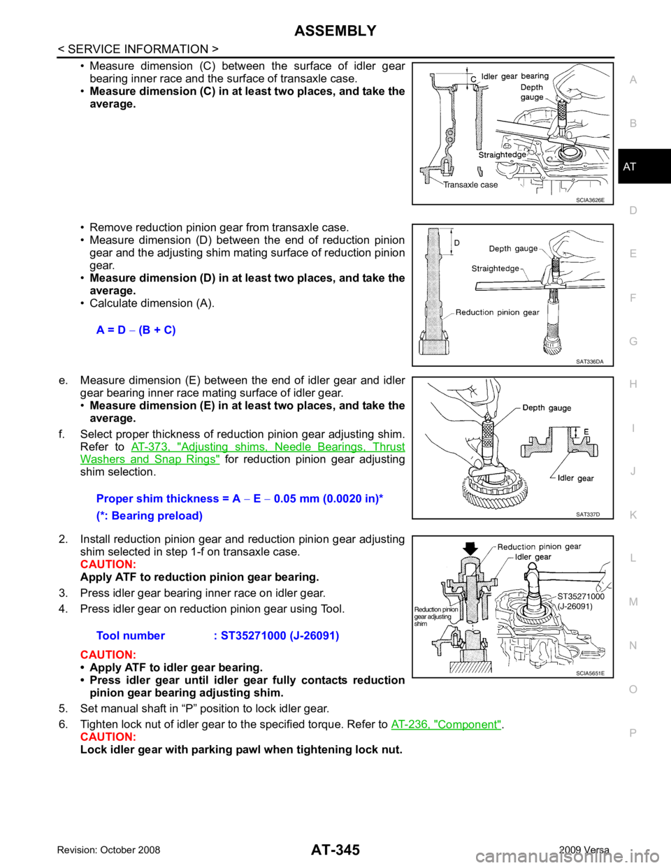
• Measure dimension (C) between the surface of idler gear
bearing inner race and the surface of transaxle case.
• Measure dimension (C) in at least two places, and take the
average.
• Remove reduction pinion gear from transaxle case.
• Measure dimension (D) between the end of reduction pinion gear and the adjusting shim mating surface of reduction pinion
gear.
• Measure dimension (D) in at least two places, and take the
average.
• Calculate dimension (A).
e. Measure dimension (E) between the end of idler gear and idler gear bearing inner race mating surface of idler gear.
• Measure dimension (E) in at least two places, and take the
average.
f. Select proper thickness of reduction pinion gear adjusting shim. Refer to AT-373, " Adjusting shims, Needle Bearings, Thrust
Washers and Snap Rings " for reduction pinion gear adjusting
shim selection.
2. Install reduction pinion gear and reduction pinion gear adjusting shim selected in step 1-f on transaxle case.
CAUTION:
Apply ATF to reduction pinion gear bearing.
3. Press idler gear bearing inner race on idler gear.
4. Press idler gear on reduction pinion gear using Tool.
CAUTION:
• Apply ATF to idler gear bearing.
• Press idler gear until idler gear fully contacts reduction
pinion gear bearin g adjusting shim.
5. Set manual shaft in “P” position to lock idler gear.
6. Tighten lock nut of idler gear to the specified torque. Refer to AT-236, " Component " .
CAUTION:
Lock idler gear with parking pa wl when tightening lock nut.