2009 NISSAN TIIDA brake fluid
[x] Cancel search: brake fluidPage 986 of 4331
![NISSAN TIIDA 2009 Service Repair Manual CVT-42< SERVICE INFORMATION >
[RE0F08A]
TROUBLE DIAGNOSIS
6. While holding down the foot brake, gradually press down the accelerator pedal.
7. Quickly read off the stall speed, and the NISSAN TIIDA 2009 Service Repair Manual CVT-42< SERVICE INFORMATION >
[RE0F08A]
TROUBLE DIAGNOSIS
6. While holding down the foot brake, gradually press down the accelerator pedal.
7. Quickly read off the stall speed, and the](/manual-img/5/57398/w960_57398-985.png)
CVT-42< SERVICE INFORMATION >
[RE0F08A]
TROUBLE DIAGNOSIS
6. While holding down the foot brake, gradually press down the accelerator pedal.
7. Quickly read off the stall speed, and then quickly remove your foot from the accelerator pedal.
CAUTION:
Do not hold down the accelerator pedal for more than 5 sec-
onds during this test.
8. Move the selector lever to the “N” position.
9. Cool down the CVT fluid. CAUTION:
Run the engine at idle for at least 1 minute.
10. Repeat steps 6 through 9 with selector lever in “R” position.
Judgement Stall Test
O: Stall speed within standard value position.
H: Stall speed is higher than standard value.
L: Stall speed is lower than standard value.
LINE PRESSURE TEST
Line Pressure Test Port
Line Pressure Test Procedure
1. Inspect the amount of engine oil and replenish if necessary.
2. Drive the car for about 10 minutes to warm it up so that the CVT fluid reaches in the range of 50 to 80°C
(122 to 176 °F), then inspect the amount of CVT fluid and replenish if necessary.
NOTE: Stall speed: 2,600 - 3,150 rpm SAT514G
SAT771B
Selector lever position
Expected problem location
“D” “R”
Stall rotation H O • Forward clutch
O H • Reverse brake L L • Engine and torque converter one-way clutch
H H • Line pressure low
• Primary pulley
• Secondary pulley
• Steel belt SCIA6184E
Page 987 of 4331

CVT
N
O P
The CVT fluid temperature rises in the range of 50 - 80
°C (122 - 176 °F) during 10 minutes of driving.
3. After warming up CVT, remove the oil pressure detection plug and install the oil pressure gauge [special service tool: - (OTC3492)].
CAUTION:
When using the oil pressure gauge, be sure to use the O-ring attached to the oil pressure detec-
tion plug.
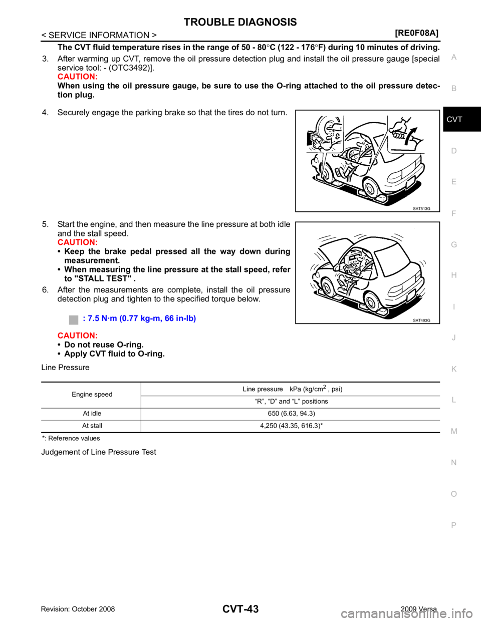
4. Securely engage the parking brake so that the tires do not turn.
5. Start the engine, and then measure the line pressure at both idle and the stall speed.
CAUTION:
• Keep the brake pedal pressed all the way down during
measurement.
• When measuring the line pressure at the stall speed, refer
to "STALL TEST" .
6. After the measurements are complete, install the oil pressure detection plug and tighten to the specified torque below.
CAUTION:
• Do not reuse O-ring.
• Apply CVT fluid to O-ring.
Line Pressure
*: Reference values
Judgement of Line Pressure Test
Page 998 of 4331

How to Perform Trouble Diag-
nosis for Quick and Accurate Repair " . Reference pages are provided following the items.
Display Items List X: Applicable —: Not applicable
Item name Description
ENGINE BRAKE ADJ. The engine brake level setting can be canceled.
CONFORM CVTF DETERIORTN The CVT fluid deterioration level can be checked. CONTROL
UNIT(CAN) When detecting error during the initial diagnosis of CAN con-
troller of TCM U1010 U1010
CVT-63STARTER RELAY/
CIRC Is this signal is ON other than in “P” or “N” position, this is
judged to be a malfunction
(And if it is OFF in “P” or “N” position, this is judged to be a
malfunction too) P0615 —
CVT-64BRAKE SW/CIRC When the brake switch does
not switch to ON or OFF P0703 — CVT-67PNP SW/CIRC
• PNP switch 1-4 signals input with impossible pattern
• PNP switch 3 monitor terminal open or short circuit P0705 P0705
CVT-69ATF TEMP SEN/
CIRC During running, the CVT fluid temperature sensor signal volt-
age is excessively high or low P0710 P0710
CVT-75INPUT SPD SEN/
CIRC • Input speed sensor (primary speed sensor) signal is not in-
put due to an open circuit
• An unexpected signal is input when vehicle is being driven P0715 P0715
CVT-80
Page 1001 of 4331

CVT
N
O P
ENG SPEED (rpm) — X
SLIP REV (rpm) — X Difference between engine speed and primary
pulley speed
GEAR RATIO — X
G SPEED (G) — —
ACC PEDAL OPEN (0.0/8) X X Degree of opening for accelerator recognized by
the TCM
For fail-safe operation, the specific value used for
control is displayed.
TRQ RTO — —
SEC PRESS (MPa) — X
PRI PRESS (MPa) — X
ATFTEMP COUNT — X Means CVT fluid temperature. Actual oil temper-
ature ( °C) cannot be checked unless a numeric
value is converted. Refer to CVT-12 .
DSR REV (rpm) — —
DGEAR RATIO — —
DSTM STEP (step) — —
STM STEP (step) — X
LU PRS (MPa) — —
LINE PRS (MPa) — —
TGT SEC PRESS (MPa) — —
ISOLT1 (A) — X Torque converter clutch solenoid valve output
current
ISOLT2 (A) — X Pressure control solenoid valve A (line pressure
solenoid valve) output current
ISOLT3 (A) — X Pressure control solenoid valve B (secondary
pressure solenoid valve) output current
SOLMON1 (A) X X Torque converter clutch solenoid valve monitor
current
SOLMON2 (A) X X Pressure control solenoid valve A (line pressure
solenoid valve) monitor current
SOLMON3 (A) X X Pressure control solenoid valve B (secondary
pressure solenoid va lve) monitor current
INH SW3M (ON/OFF) X — PNP switch 3 ON-OFF status monitor
INH SW4 (ON/OFF) X — PNP switch 4 ON-OFF status
INH SW3 (ON/OFF) X — PNP switch 3 ON-OFF status
INH SW2 (ON/OFF) X — PNP switch 2 ON-OFF status
INH SW1 (ON/OFF) X — PNP switch 1 ON-OFF status
BRAKE SW (ON/OFF) X X Stop lamp switch (Signal input with CAN comuni-
cation)
Monitored item (Unit)
Monitor item selection
Remarks
ECU IN-
PUT SIG- NALS MAIN SIG-
NALS SELEC-
TION
FROM
MENU
Page 1107 of 4331

CVT
N
O P
Vehicle Speed Does Not
Change in "D" Position INFOID:0000000004667101
SYMPTOM: Vehicle speed does not change in “D” position while the cruise test.
DIAGNOSTIC PROCEDURE CONSULT-III Functi
on (TRANSMISSION) " .
Is any malfunction detected by self-diagnosis? YES >> Check the malfunctioning system. Refer to
CVT-51, " CONSULT-III Function (TRANSMISSION) " .
NO >> GO TO 2. Checking of CVT Position "
OK or NG
OK >> GO TO 3.
NG >> Adjust CVT position. Refer to CVT-175, " Adjustment of CVT Position " .
Checking CVT Fluid " .
OK or NG OK >> GO TO 4.
NG >> Refill CVT fluid. Inspections before Trouble Diagnosis " .
OK or NG OK >> GO TO 5.
NG >> Check the malfunctioning item. Refer to CVT-40, " Inspections before Trouble Diagnosis " .
Inspections before Trouble Diagnosis " .
OK or NG OK >> GO TO 6.
NG >> Check the malfunctioning item. Refer to CVT-40, " Inspections before Trouble Diagnosis " .
Cruise Test " .
OK or NG OK >>
INSPECTION END
NG >> GO TO 7. TCM Terminal and Reference Value " .
2. If NG, re-check TCM pin terminals for dam age or loose connection with harness connector.
OK or NG OK >> Replace the transaxle assembly. Refer to
CVT-182, " Removal and Installation " .
NG >> Repair or replace damaged parts.
Vehicle Does Not Decelerate by Engine Brake INFOID:0000000004667102
SYMPTOM: Engine brake does not operate when releasing the accelerator pedal while the cruise test.
DIAGNOSTIC PROCEDURE
Page 1137 of 4331
![NISSAN TIIDA 2009 Service Repair Manual PRECAUTIONS
CVT-193
< SERVICE INFORMATION >
[RE0F08B] D
E
F
G H
I
J
K L
M A
B CVT
N
O P
•
Before connecting or disconn ecting the TCM harness connec-
tor, turn ignition switch OF F and disconn NISSAN TIIDA 2009 Service Repair Manual PRECAUTIONS
CVT-193
< SERVICE INFORMATION >
[RE0F08B] D
E
F
G H
I
J
K L
M A
B CVT
N
O P
•
Before connecting or disconn ecting the TCM harness connec-
tor, turn ignition switch OF F and disconn](/manual-img/5/57398/w960_57398-1136.png)
PRECAUTIONS
CVT-193
< SERVICE INFORMATION >
[RE0F08B] D
E
F
G H
I
J
K L
M A
B CVT
N
O P
•
Before connecting or disconn ecting the TCM harness connec-
tor, turn ignition switch OF F and disconnect negative battery
cable. Because battery voltage is applied to TCM even if igni-
tion switch is turned OFF.
• When connecting or disconnect ing pin connectors into or
from TCM, take care not to damage pin terminals (bend or
break).
When connecting pin connectors make sure that there are not
any bends or breaks on TCM pin terminal.
• Before replacing TCM, perform TCM input/output signal
inspection and make sure whether TCM functions properly or
not. CVT-228, " TCM Terminal and Reference Value " .
• After performing each TROUBL E DIAGNOSIS, perform “DTC
Confirmation Procedure”.
If the repair is completed the DTC should not be displayed in
the “DTC Confirmation Procedure”.
• Always use the specified br and of CVT fluid. Refer to MA-14, " Flu-
ids and Lubricants " .
• Use lint-free paper, not cloth rags, during work.
• After replacing the CVT fluid, dispose of the waste oil using the methods prescribed by law, ordinance, etc.
Service Notice or Precaution INFOID:0000000004305567
CVT FLUID COOLER SERVICE If CVT fluid contains friction material (clutches, brakes , etc.), or if an CVT is replaced, inspect and clean the
CVT fluid cooler mounted in the radiator or replace t he radiator. Flush cooler lines using cleaning solvent and
compressed air after repair. For CVT fluid cooler cleaning procedure, refer to CVT-197, " CVT Fluid Cooler
Cleaning " . For radiator replacement, refer to
CO-38 .
OBD-II SELF-DIAGNOSIS SEF289H
SEF291H
MEF040DA
SEF217U
Page 1140 of 4331
![NISSAN TIIDA 2009 Service Repair Manual CVT-196< SERVICE INFORMATION >
[RE0F08B]
CVT FLUID
CVT FLUID
Checking CVT Fluid INFOID:0000000004305570
FLUID LEVEL CHECK
Fluid level should be checked with the fluid warmed up to 50 ° to 80 °C (122 NISSAN TIIDA 2009 Service Repair Manual CVT-196< SERVICE INFORMATION >
[RE0F08B]
CVT FLUID
CVT FLUID
Checking CVT Fluid INFOID:0000000004305570
FLUID LEVEL CHECK
Fluid level should be checked with the fluid warmed up to 50 ° to 80 °C (122](/manual-img/5/57398/w960_57398-1139.png)
CVT-196< SERVICE INFORMATION >
[RE0F08B]
CVT FLUID
CVT FLUID
Checking CVT Fluid INFOID:0000000004305570
FLUID LEVEL CHECK
Fluid level should be checked with the fluid warmed up to 50 ° to 80 °C (122 ° to 176 °F).
1. Check for fluid leakage.
2. With the engine warmed up, drive the vehicle to warm up the CVT fluid. When ambient temperature is 20 °C (68 °F), it takes
about 10 minutes for the CVT fluid to warm up to 50 ° to 80 °C
(122 ° to 176 °F).
3. Park the vehicle on a level surface and set the parking brake.
4. With engine at idle, while depressing brake pedal, move the selector lever throughout the entire shift range and return it to
the “P” position.
5. Press the tab on the CVT fluid level gauge to release the lock and pull out the CVT fluid level gauge from the CVT fluid charg-
ing pipe.
6. Wipe fluid off the CVT fluid level gauge. Then rotate the CVT fluid level gauge 180 ° and re-insert it into the CVT charging pipe
as far as it will go.
CAUTION:
Always use lint free paper towels to wipe fluid off the CVT
fluid level gauge.
7. Remove the CVT fluid level gauge and check that the fluid level is within the specified range as shown. If the fluid level is at or
below the low side of the range, add the necessary specified
NISSAN CVT fluid through the CVT charging pipe.
CAUTION:
• Only use specified NISSAN CVT fluid.
• Do not overfill the CVT.
8. Install the CVT fluid level gauge to the CVT fluid charging pipe until it locks. CAUTION:
When CVT fluid level gauge is in stalled into the CVT fluid charging pipe, make sure that the CVT
fluid level gauge is securely locked in place. SMA146B
SCIA1933E
SCIA1931E
Fluid grade: Refer to
MA-14, " Fluids and Lubri-
cants " .
SCIA1932E
Page 1141 of 4331
![NISSAN TIIDA 2009 Service Repair Manual CVT FLUID
CVT-197
< SERVICE INFORMATION >
[RE0F08B] D
E
F
G H
I
J
K L
M A
B CVT
N
O P
FLUID CONDITION CHECK
Changing CVT Fluid INFOID:0000000004305571
1. Warm up CVT fluid by driving the vehicle for 1 NISSAN TIIDA 2009 Service Repair Manual CVT FLUID
CVT-197
< SERVICE INFORMATION >
[RE0F08B] D
E
F
G H
I
J
K L
M A
B CVT
N
O P
FLUID CONDITION CHECK
Changing CVT Fluid INFOID:0000000004305571
1. Warm up CVT fluid by driving the vehicle for 1](/manual-img/5/57398/w960_57398-1140.png)
CVT FLUID
CVT-197
< SERVICE INFORMATION >
[RE0F08B] D
E
F
G H
I
J
K L
M A
B CVT
N
O P
FLUID CONDITION CHECK
Changing CVT Fluid INFOID:0000000004305571
1. Warm up CVT fluid by driving the vehicle for 10 minutes.
• : Vehicle front
• Radiator (2)
• CVT fluid cooler hose [inlet side (3)]
• Transaxle assembly (4)
2. Drain CVT fluid from CVT fluid cooler hose [outlet side (1)] and refill with new specified NISSAN CVT fluid in the CVT fluid
charging pipe with the engine running at idle speed.
CAUTION:
Only use the specifi ed NISSAN CVT fluid.
3. Refill until new CVT fluid comes out from CVT fluid cooler hose [outlet side (1)]. NOTE:
About 30 to 50% extra fluid will be required for this procedure.
4. Check fluid level and condition. Refer to CVT-196, " Checking CVT Fluid " .
CAUTION:
Delete CVT fluid deterioration date with CO NSULT-III after changing CVT fluid. Refer to CVT-230," CONSULT-III Function (TRANSMISSION) " .
CVT Fluid Cooler Cleaning INFOID:0000000004305572
Whenever a CVT is repaired, overhauled, or replaced, t he CVT fluid cooler mounted in the radiator must be
inspected and cleaned.
Metal debris and friction material, if present, can be trapped or become deposit in the CVT fluid cooler. This
debris can contaminate the newly serviced CVT or, in severe cases, can block or restrict the flow of CVT fluid.
In either case, malfunction of the newly serviced CVT may occur.
Debris, if present, may deposit as CVT fluid enters the cool er inlet. It will be necessary to back flush the cooler
through the cooler outlet in order to flush out any built up debris.
CVT FLUID COOLER CLEANING PROCEDURE 1. Identify the CVT inlet and outlet fluid cooler hoses.
2. Position an oil pan under the inlet and outlet cooler hoses. Fluid status Conceivable cause Required operation
Varnished (viscous
varnish state) Clutch, brake
scorched Replace the CVT fluid and check the
CVT main unit and the vehicle for
malfunctions (wire harness, cooler
pipes, etc.)
Milky white or cloudy Water in the fluid Replace the CVT fluid and check for places where water is getting in.
Large amount of
metal powder mixed
in fluid Unusual wear of
sliding parts within
CVT Replace the CVT fluid and check for
improper operation of the CVT. ATA0022D
Fluid capacity and grade: Refer to
MA-14, " Fluids
and Lubricants " .
SCIA6088E