2009 NISSAN TIIDA brake fluid
[x] Cancel search: brake fluidPage 1277 of 4331
CVT
N
O P
OK >> Replace the transaxle assembly. Refer to
CVT-354, " Removal and Installation " .
NG >> Repair or replace damaged parts.
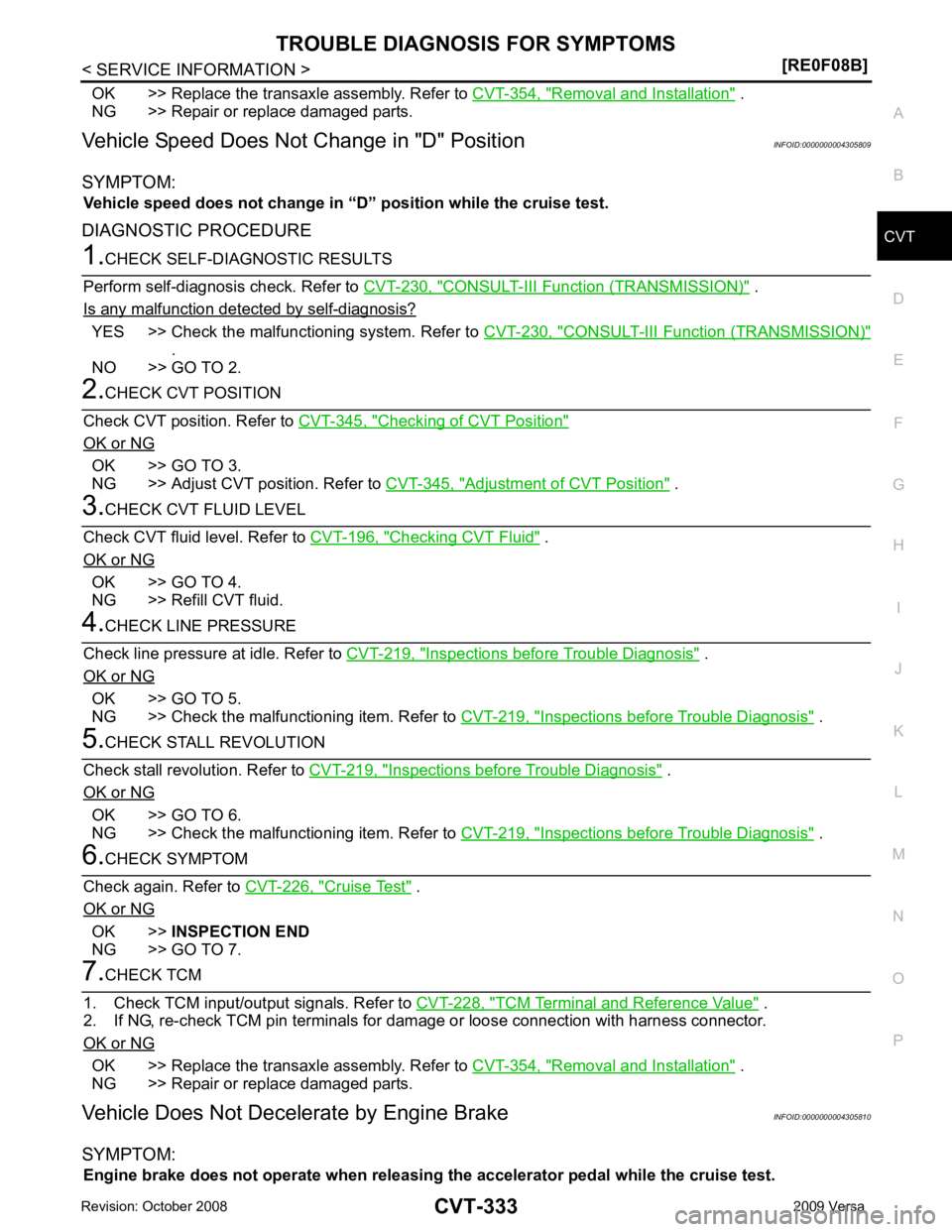
Vehicle Speed Does Not Change in "D" Position INFOID:0000000004305809
SYMPTOM: Vehicle speed does not change in “D” position while the cruise test.
DIAGNOSTIC PROCEDURE CONSULT-III Functi
on (TRANSMISSION) " .
Is any malfunction detected by self-diagnosis? YES >> Check the malfuncti
oning system. Refer to CVT-230, " CONSULT-III Function (TRANSMISSION) "
.
NO >> GO TO 2. Checking of CVT Position "
OK or NG
OK >> GO TO 3.
NG >> Adjust CVT position. Refer to CVT-345, " Adjustment of CVT Position " .
Checking CVT Fluid " .
OK or NG OK >> GO TO 4.
NG >> Refill CVT fluid. Inspections before Trouble Diagnosis " .
OK or NG OK >> GO TO 5.
NG >> Check the malfunctioning item. Refer to CVT-219, " Inspections before Trouble Diagnosis " .
Inspections before Trouble Diagnosis " .
OK or NG OK >> GO TO 6.
NG >> Check the malfunctioning item. Refer to CVT-219, " Inspections before Trouble Diagnosis " .
Cruise Test " .
OK or NG OK >>
INSPECTION END
NG >> GO TO 7. TCM Terminal and Reference Value " .
2. If NG, re-check TCM pin terminals for dam age or loose connection with harness connector.
OK or NG OK >> Replace the transaxle assembly. Refer to
CVT-354, " Removal and Installation " .
NG >> Repair or replace damaged parts.
Vehicle Does Not Decelerate by Engine Brake INFOID:0000000004305810
SYMPTOM: Engine brake does not operate when releasing the accelerator pedal while the cruise test.
Page 1311 of 4331
DI
N
O P
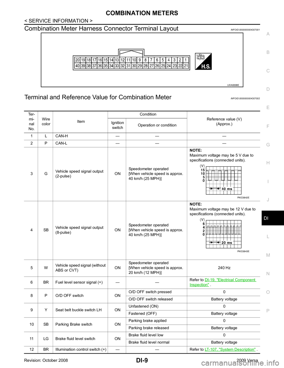
Combination Meter Harness Connector Terminal Layout
INFOID:0000000004307001
Terminal and Reference Va lue for Combination Meter INFOID:0000000004307002 Electrical Component
Inspection " .
8 P O/D OFF switch ON O/D OFF switch pressed 0
O/D OFF switch released Battery voltage
9 Y Seat belt buckle switch LH ON Unfastened (ON) 0
Fastened (OFF) Battery voltage
10 SB Parking Brake switch ON Parking brake applied 0
Parking brake released Battery voltage
11 LG Brake fluid level switch ON Brake fluid level low 0
Brake fluid level normal Battery voltage
12 BR Illumination control switch (+) — — Refer to LT-107, " System Description " .
Page 1312 of 4331
System Description " .
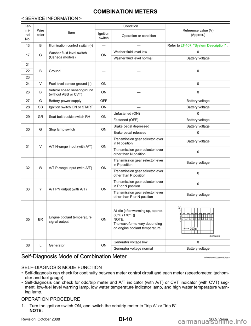
17 G Washer fluid level switch
(Canada models) ONWasher fluid level low 0
Washer fluid level normal Battery voltage
21 B Ground — — 0
22
23
24 V Fuel level sensor ground (-) ON — 0
26 B Vehicle speed sensor ground
(without ABS or CVT) ON — 0
27 G Battery power supply OFF — Battery voltage
28 SB Ignition switch ON or START ON — Battery voltage
29 GR Seat belt buckle switch RH ON Unfastened (ON) 0
Fastened (OFF) Battery voltage
30 G Stop lamp switch ON Brake pedal depressed Battery voltage
Brake pedal released 0
31 V A/T N-range input (with A/T) ON Transmission gear selector lever
in N position Battery voltage
Transmission gear selector lever
other than N position 0
32 W A/T P-range input (with A/T) ON Transmission gear selector lever
in P position Battery voltage
Transmission gear selector lever
other than P position 0
33 Y A/T PN output (with A/T) ON Transmission gear selector lever
in P or N position 0
Transmission gear selector lever
other than P or N position Battery voltage
35 BR Engine coolant temperature
signal output ONAt idle [after warming up, approx.
80 °C (176 °F)]
NOTE:
The waveforms vary depending
on engine coolant temperature.
38 L Generator ON Generator voltage low 0
Generator voltage normal Battery voltage
Ter-
mi-
nal
No. Wire
color Item Condition
Reference value (V)
(Approx.)
Ignition
switch Operation or condition
Page 1315 of 4331

DI
N
O P
NOTE:
Some items are not available due to vehicle specification.
*: The monitor will indicate “OFF” even though the brake warnin g lamp is on if either of the following conditions exist.
• The parking brake is engaged
• The brake fluid level is low
Trouble Diagnosis INFOID:0000000004307005
HOW TO PERFORM TROUBLE DIAGNOSIS 1. Confirm the symptom or customer complaint.
2. Perform preliminary check. Refer to "PRELIMINARY CHECK" .
3. According to the symptom chart, repair or replace the cause of the malfunction. Refer to DI-14, " Symptom
Chart " .
4. Does the meter operate normally? If so, GO TO 5. If not, GO TO 2.
5. Inspection End.
PRELIMINARY CHECK Self-Diagnosis Mode of Combination Meter " .
Does self - diagnosis mode operate?
YES >> GO TO 2.
TURN IND [ON/OFF] X Indicates [ON/O
FF] condition of turn indicator.
OIL W/L [ON/OFF] X Indicates [ON/OFF] condition of oil pressure warning lamp.
ABS W/L [ON/OFF] X Indicates [ON/O FF] condition of ABS warning lamp.
BRAKE W/L [ON/OFF] X Indicates [ON/OFF] condition of brake warning lamp.*
KEY G W/L [ON/OFF] X Indicates [ON/OFF] condition of KEY warning lamp (green).
KEY R W/L [ON/OFF] X Indicates [ON/OFF] condition of KEY warning lamp (red).
KEY KNOB W/L [ON/OFF] X Indicates [ON/OFF] condition of LOCK warning lamp.
PNP P SW [ON/OFF] X X Indicates [ON/OFF] condition of inhibitor P switch.
PNP N SW [ON/OFF] X X Indicates [ON/OFF] condition of inhibitor N switch.
O/D OFF SW [ON/OFF] X Indicates [ON/ OFF] condition of O/D OFF switch.
BRAKE SW [ON/OFF] X Indicates [ON/OFF] condition of parking brake switch.
P RANGE IND [ON/OFF] X X Indicates [ON/OFF] condition of A/T or CVT shift P range indi-
cator.
R RANGE IND [ON/OFF] X X Indicates [ON/OFF] condition of A/T or CVT shift R range indi-
cator.
N RANGE IND [ON/OFF] X X Indicates [ON/OFF] condition of A/T or CVT shift N range indi-
cator.
D RANGE IND [ON/OFF] X X Indicates [ON/OFF] condition of A/T or CVT shift D range indi-
cator.
2 RANGE IND [ON/OFF] X X Indicates [ON/OFF] condition of A/T shift 2 range indicator.
L RANGE IND [ON/OFF] X X Indicates [ON/OFF] condition of CVT shift L range indicator.
1 RANGE IND [ON/OFF] X X Indicates [ON/OFF] condition of A/T shift 1 range indicator.
CRUISE IND [ON/OFF] X Indicates [ON/O FF] condition of CRUISE indicator.
SET IND [ON/OFF] X Indicates [ON/OFF] condition of SET indicator.
O/D OFF W/L [ON/OFF] X Indicates [ON/OFF] condition of O/D OFF indicator lamp.
e-4WD W/L [ON/OFF] X This item is not used for this model. “OFF” is always displayed.
EPS W/L [ON/OFF] X Indicates [ON/O FF] condition of EPS warning lamp.
Display item [Unit]
MAIN
SIGNALS SELECTION
FROM MENU Contents
Page 1929 of 4331
![NISSAN TIIDA 2009 Service Repair Manual EC
NP
O
[Air conditioner, headlamp, rear window defogger]
On vehicles equipped with daytime light systems, if the parking brake is applied before the engine is
started the headlamp will not be illumi NISSAN TIIDA 2009 Service Repair Manual EC
NP
O
[Air conditioner, headlamp, rear window defogger]
On vehicles equipped with daytime light systems, if the parking brake is applied before the engine is
started the headlamp will not be illumi](/manual-img/5/57398/w960_57398-1928.png)
EC
NP
O
[Air conditioner, headlamp, rear window defogger]
On vehicles equipped with daytime light systems, if the parking brake is applied before the engine is
started the headlamp will not be illuminated.
• Steering wheel: Neutral (Straight-ahead position)
• Vehicle speed: Stopped
• Transmission: Warmed-up
- Models with CONSULT-III (A/T and CVT models)
• Drive vehicle until “FLUID TEMP SE” in “DATA MONI TOR” mode of “A/T” or “CVT” system indicates less
than 0.9V.
- Models without CONSULT-III (A/T and CVT models) and M/T models
• Drive vehicle for 10 minutes.
OPERATION PROCEDURE
With CONSULT-III
1. Perform EC-572, " Accelerator Pedal Released Position Learning " .
2. Perform EC-572, " Throttle Valve Closed Position Learning " .
3. Start engine and warm it up to normal operating temperature.
4. Check that all items listed under the topic PREP ARATION (previously mentioned) are in good order.
5. Select “IDLE AIR VOL LEA RN” in “WORK SUPPORT” mode.
6. Touch “START” and wait 20 seconds.
7. Make sure that “CMPLT” is displayed on CONSULT-III screen. If “CMPLT” is not displayed, Idle Air Vol-
ume Learning will not be carried out successfully. In this case, find the cause of the incident by referring to
the DIAGNOSTIC PROCEDURE below.
8. Rev up the engine two or three times and make sure that idle speed and ignition timing are within the specifications.
Refer to EC-566, " Basic Inspection " .
Without CONSULT-III
NOTE:
• It is better to count the time accurately with a clock.
• It is impossible to switch the di agnostic mode when an accelerator pedal position sensor circuit has
a malfunction.
1. Perform EC-572, " Accelerator Pedal Released Position Learning " .
2. Perform EC-572, " Throttle Valve Closed Position Learning " .
3. Start engine and warm it up to normal operating temperature.
4. Check that all items listed under the topic PREP ARATION (previously mentioned) are in good order.
5. Turn ignition switch OFF and wait at least 10 seconds.
6. Confirm that accelerator pedal is fully releas ed, turn ignition switch ON and wait 3 seconds.
7. Repeat the following procedure quick ly five times within 5 seconds.
a. Fully depress the accelerator pedal.
b. Fully release the accelerator pedal.
8. Wait 7 seconds, fully depress the accelerator pedal and keep it for approx. 20 seconds until the MIL stops
blinking and turned ON.
9. Fully release the accelerator pedal within 3 seconds after the MIL turned ON.
10. Start engine and let it idle.
Page 2441 of 4331
![NISSAN TIIDA 2009 Service Repair Manual EC
NP
O
[Air conditioner, headlamp, rear window defogger]
On vehicles equipped with daytime light systems, if the parking brake is applied before the engine is
started the headlamp will not be illumi NISSAN TIIDA 2009 Service Repair Manual EC
NP
O
[Air conditioner, headlamp, rear window defogger]
On vehicles equipped with daytime light systems, if the parking brake is applied before the engine is
started the headlamp will not be illumi](/manual-img/5/57398/w960_57398-2440.png)
EC
NP
O
[Air conditioner, headlamp, rear window defogger]
On vehicles equipped with daytime light systems, if the parking brake is applied before the engine is
started the headlamp will not be illuminated.
• Steering wheel: Neutral (Straight-ahead position)
• Vehicle speed: Stopped
• Transmission: Warmed-up
- Models with CONSULT-III (A/T and CVT models)
• Drive vehicle until “FLUID TEMP SE” in “DATA MONI TOR” mode of “A/T” or “CVT” system indicates less
than 0.9V.
- Models without CONSULT-III (A/T and CVT models) and M/T models
• Drive vehicle for 10 minutes.
OPERATION PROCEDURE
With CONSULT-III
1. Perform EC-1084, " Accelerator Pedal Released Position Learning " .
2. Perform EC-1084, " Throttle Valve Closed Position Learning " .
3. Start engine and warm it up to normal operating temperature.
4. Check that all items listed under the topic PREP ARATION (previously mentioned) are in good order.
5. Select “IDLE AIR VOL LEA RN” in “WORK SUPPORT” mode.
6. Touch “START” and wait 20 seconds.
7. Make sure that “CMPLT” is displayed on CONSULT-III screen. If “CMPLT” is not displayed, Idle Air Vol-
ume Learning will not be carried out successfully. In this case, find the cause of the incident by referring to
the DIAGNOSTIC PROCEDURE below.
8. Rev up the engine two or three times and make sure that idle speed and ignition timing are within the specifications.
Refer to EC-1078, " Basic Inspection " .
Without CONSULT-III
NOTE:
• It is better to count the time accurately with a clock.
• It is impossible to switch the di agnostic mode when an accelerator pedal position sensor circuit has
a malfunction.
1. Perform EC-1084, " Accelerator Pedal Released Position Learning " .
2. Perform EC-1084, " Throttle Valve Closed Position Learning " .
3. Start engine and warm it up to normal operating temperature.
4. Check that all items listed under the topic PREP ARATION (previously mentioned) are in good order.
5. Turn ignition switch OFF and wait at least 10 seconds.
6. Confirm that accelerator pedal is fully releas ed, turn ignition switch ON and wait 3 seconds.
7. Repeat the following procedure quick ly five times within 5 seconds.
a. Fully depress the accelerator pedal.
b. Fully release the accelerator pedal.
8. Wait 7 seconds, fully depress the accelerator pedal and keep it for approx. 20 seconds until the MIL stops
blinking and turned ON.
9. Fully release the accelerator pedal within 3 seconds after the MIL turned ON.
10. Start engine and let it idle.
Page 3004 of 4331
EM
NP
O
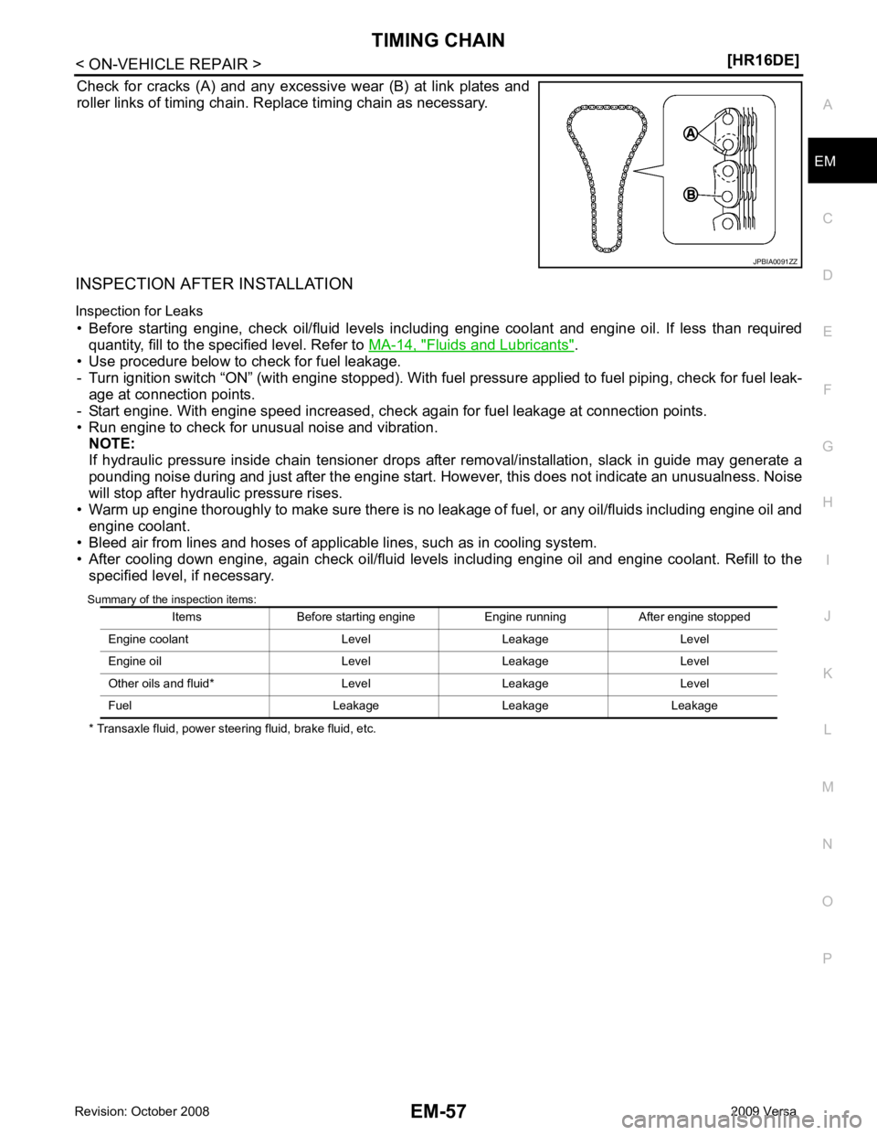
Check for cracks (A) and any excessive wear (B) at link plates and
roller links of timing chain. Replace timing chain as necessary.
INSPECTION AFTER INSTALLATION
Inspection for Leaks • Before starting engine, check oil/fluid levels incl uding engine coolant and engine oil. If less than required
quantity, fill to the specified level. Refer to MA-14, " Fluids and Lubricants " .
• Use procedure below to check for fuel leakage.
- Turn ignition switch “ON” (with engine stopped). With fuel pressure applied to fuel piping, check for fuel leak-
age at connection points.
- Start engine. With engine speed increased, check again for fuel leakage at connection points.
• Run engine to check for unusual noise and vibration. NOTE:
If hydraulic pressure inside chain tensioner drops after removal/installation, slack in guide may generate a
pounding noise during and just after the engine start. However, this does not indicate an unusualness. Noise
will stop after hydraulic pressure rises.
• Warm up engine thoroughly to make sure there is no leak age of fuel, or any oil/fluids including engine oil and
engine coolant.
• Bleed air from lines and hoses of applicable lines, such as in cooling system.
• After cooling down engine, again check oil/fluid levels including engine oil and engine coolant. Refill to the specified level, if necessary.
Summary of the inspection items:
* Transaxle fluid, power steering fluid, brake fluid, etc.
Page 3021 of 4331
Fluids and Lubricants " .
• Use procedure below to check for fuel leakage.
- Turn ignition switch “ON” (with engine stopped). With fuel pressure applied to fuel piping, check for fuel leak-
age at connection points.
- Start engine. With engine speed increased, che ck again for fuel leakage at connection points.
• Run engine to check for unusual noise and vibration. NOTE:
If hydraulic pressure inside timing chain tensioner drops after removal/installation, slack in the guide may
generate a pounding noise during and just after engine start. However, this is normal. Noise will stop after
hydraulic pressure rises.
• Warm up engine thoroughly to make sure there is no leakage of fuel, or any oil/fluids including engine oil and
engine coolant.
• Bleed air from lines and hoses of applicable lines, such as in cooling system.
• After cooling down engine, again check oil/fluid levels including engine oil and engine coolant. Refill to the
specified level, if necessary.
Summary of the inspection items:
*: Transmission/transaxle/CVT fluid, power steering fluid, brake fluid, etc.
Inspection of Camshaft Sprocket (INT) Oil Groove
CAUTION:
• Perform this inspection only when DTC P0011 is de tected in self-diagnostic results of CONSULT-III
and it is directed according to inspect ion procedure of EC section. Refer to EC-133, " Diagnosis Pro-
cedure " .
• Check when engine is cold so as to pr event burns from the splashing engine oil.
1. Check engine oil level. Refer to LU-7, " Inspection " .
2. Perform the following procedure so as to prevent the engine from being unintentionally started while
checking.
a. Release the fuel pressure. Refer to EC-498, " Inspection " .
b. Remove intake manifold. Refer to EM-28, " Exploded View " .
c. Disconnect ignition coil and injector harness connectors. Refer to EM-46, " Exploded View " .
3. Remove intake valve timing control solenoid valve. Refer to EM-49, " Exploded View " .
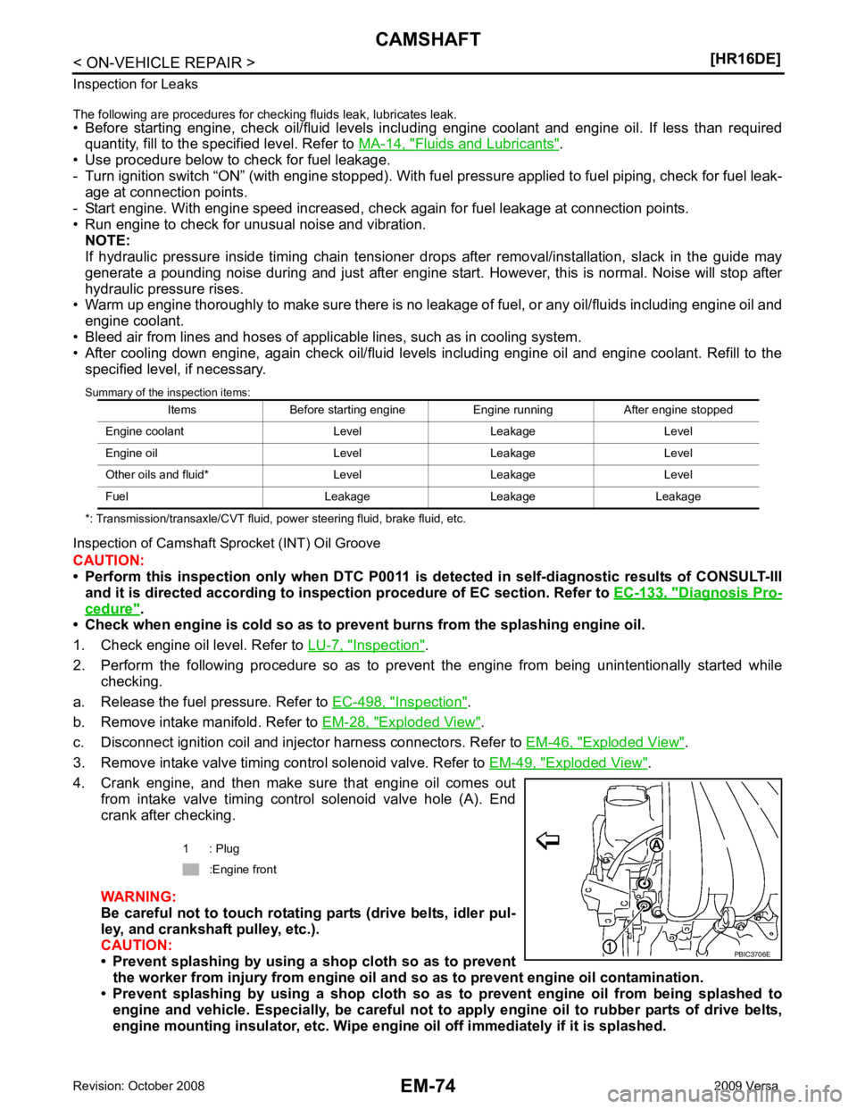
4. Crank engine, and then make sure that engine oil comes out from intake valve timing control solenoid valve hole (A). End
crank after checking.
WARNING:
Be careful not to touch rotating parts (drive belts, idler pul-
ley, and crankshaft pulley, etc.).
CAUTION:
• Prevent splashing by using a shop cloth so as to prevent
the worker from injury from engine oil an d so as to prevent engine oil contamination.
• Prevent splashing by using a shop cloth so as to prevent engine oil from being splashed to
engine and vehicle. Especially, be careful not to apply engine oil to rubber parts of drive belts,
engine mounting insulator, etc. Wipe engi ne oil off immediately if it is splashed.
Items Before starting engine Engine running After engine stopped
Engine coolant Level Leakage Level
Engine oil Level Leakage Level
Other oils and fluid* Level Leakage Level
Fuel Leakage Leakage Leakage 1 : Plug
:Engine front