2009 NISSAN TIIDA brake fluid
[x] Cancel search: brake fluidPage 3781 of 4331
MA-38< SERVICE INFORMATION >
CHASSIS AND BODY MAINTENANCE
CVT FLUID : Checking CVT Fluid (RE0F08A) INFOID:0000000004803426
FLUID LEVEL CHECK
Fluid level should be checked with the fluid warmed up to 50 ° to 80 °C (122 ° to 176 °F).
1. Check for fluid leakage.
2. With the engine warmed up, drive the vehicle to warm up the CVT fluid. When ambient temperature is 20 °C (68 °F), it takes
about 10 minutes for the CVT fluid to warm up to 50 ° to 80 °C
(122 ° to 176 °F).
3. Park the vehicle on a level surface and set the parking brake.
4. With engine at idle, while depressing brake pedal, move the selector lever throughout the entire shift range and return it to
the “P” position.
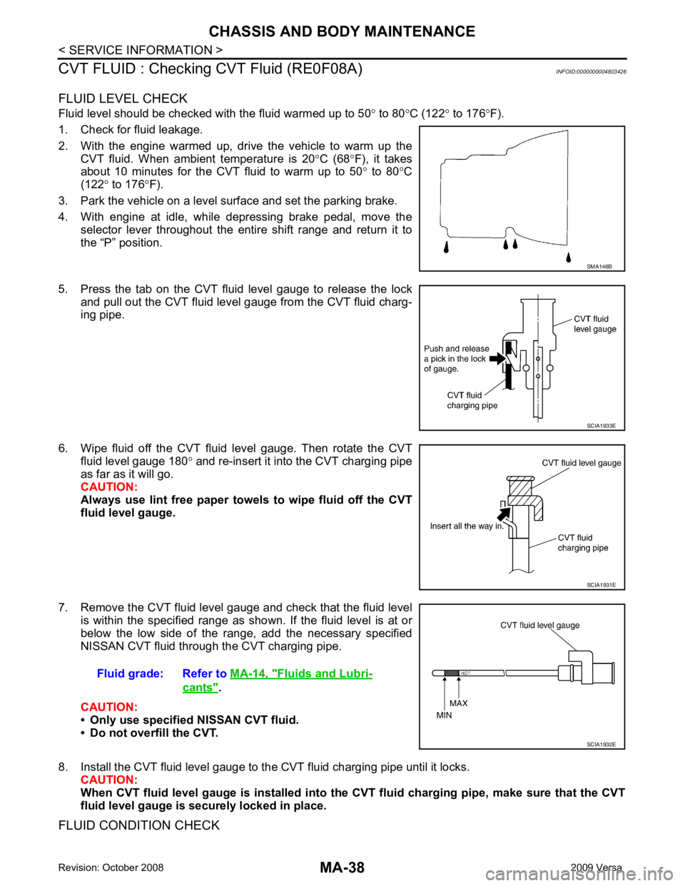
5. Press the tab on the CVT fluid level gauge to release the lock and pull out the CVT fluid level gauge from the CVT fluid charg-
ing pipe.
6. Wipe fluid off the CVT fluid level gauge. Then rotate the CVT fluid level gauge 180 ° and re-insert it into the CVT charging pipe
as far as it will go.
CAUTION:
Always use lint free paper towels to wipe fluid off the CVT
fluid level gauge.
7. Remove the CVT fluid level gauge and check that the fluid level is within the specified range as shown. If the fluid level is at or
below the low side of the range, add the necessary specified
NISSAN CVT fluid through the CVT charging pipe.
CAUTION:
• Only use specified NISSAN CVT fluid.
• Do not overfill the CVT.
8. Install the CVT fluid level gauge to the CVT fluid charging pipe until it locks. CAUTION:
When CVT fluid level gauge is in stalled into the CVT fluid charging pipe, make sure that the CVT
fluid level gauge is securely locked in place.
FLUID CONDITION CHECK SMA146B
SCIA1933E
SCIA1931E
Fluid grade: Refer to
MA-14, " Fluids and Lubri-
cants " .
SCIA1932E
Page 3782 of 4331
CHASSIS AND BODY MAINTENANCE
MA-39
< SERVICE INFORMATION >
C
D E
F
G H
I
J
K
M A
B MA
N
O P
CVT FLUID : Changing CVT Fluid (RE0F08A)
INFOID:0000000004803427
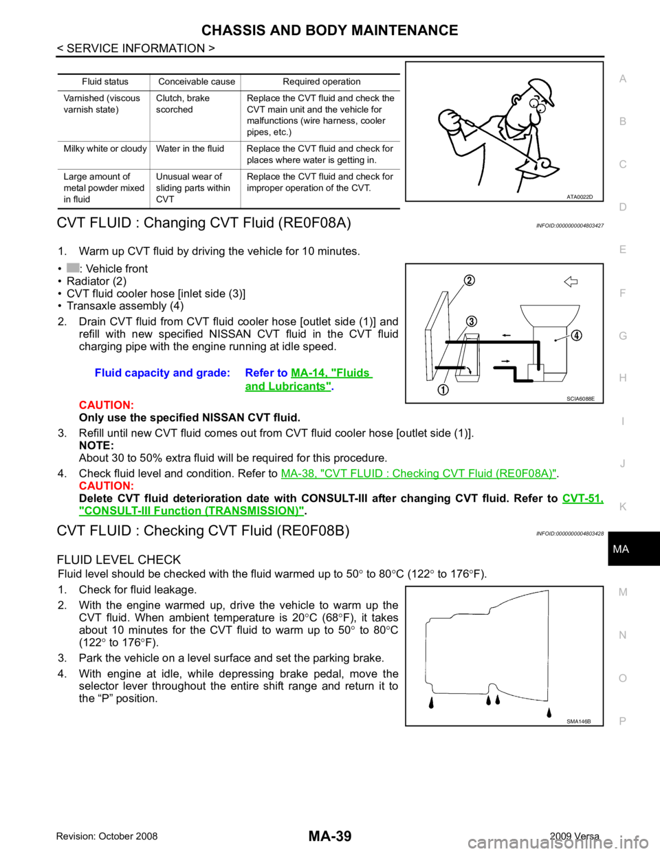
1. Warm up CVT fluid by driving the vehicle for 10 minutes.
• : Vehicle front
• Radiator (2)
• CVT fluid cooler hose [inlet side (3)]
• Transaxle assembly (4)
2. Drain CVT fluid from CVT fluid cooler hose [outlet side (1)] and refill with new specified NISSAN CVT fluid in the CVT fluid
charging pipe with the engine running at idle speed.
CAUTION:
Only use the specifi ed NISSAN CVT fluid.
3. Refill until new CVT fluid comes out from CVT fluid cooler hose [outlet side (1)]. NOTE:
About 30 to 50% extra fluid will be required for this procedure.
4. Check fluid level and condition. Refer to MA-38, " CVT FLUID : Checking CVT Fluid (RE0F08A) " .
CAUTION:
Delete CVT fluid deterioration date with CONSULT-III after changing CVT fluid. Refer to CVT-51," CONSULT-III Function (TRANSMISSION) " .
CVT FLUID : Checking CVT Fluid (RE0F08B) INFOID:0000000004803428
FLUID LEVEL CHECK Fluid level should be checked with the fluid warmed up to 50 ° to 80 °C (122 ° to 176 °F).
1. Check for fluid leakage.
2. With the engine warmed up, drive the vehicle to warm up the CVT fluid. When ambient temperature is 20 °C (68 °F), it takes
about 10 minutes for the CVT fluid to warm up to 50 ° to 80 °C
(122 ° to 176 °F).
3. Park the vehicle on a level surface and set the parking brake.
4. With engine at idle, while depressing brake pedal, move the selector lever throughout the entire shift range and return it to
the “P” position. Fluid status Conceivable cause Required operation
Varnished (viscous
varnish state) Clutch, brake
scorched Replace the CVT fluid and check the
CVT main unit and the vehicle for
malfunctions (wire harness, cooler
pipes, etc.)
Milky white or cloudy Water in the fluid Replace the CVT fluid and check for places where water is getting in.
Large amount of
metal powder mixed
in fluid Unusual wear of
sliding parts within
CVT Replace the CVT fluid and check for
improper operation of the CVT. ATA0022D
Fluid capacity and grade: Refer to
MA-14, " Fluids
and Lubricants " .
SCIA6088E
SMA146B
Page 3783 of 4331
MA-40< SERVICE INFORMATION >
CHASSIS AND BODY MAINTENANCE
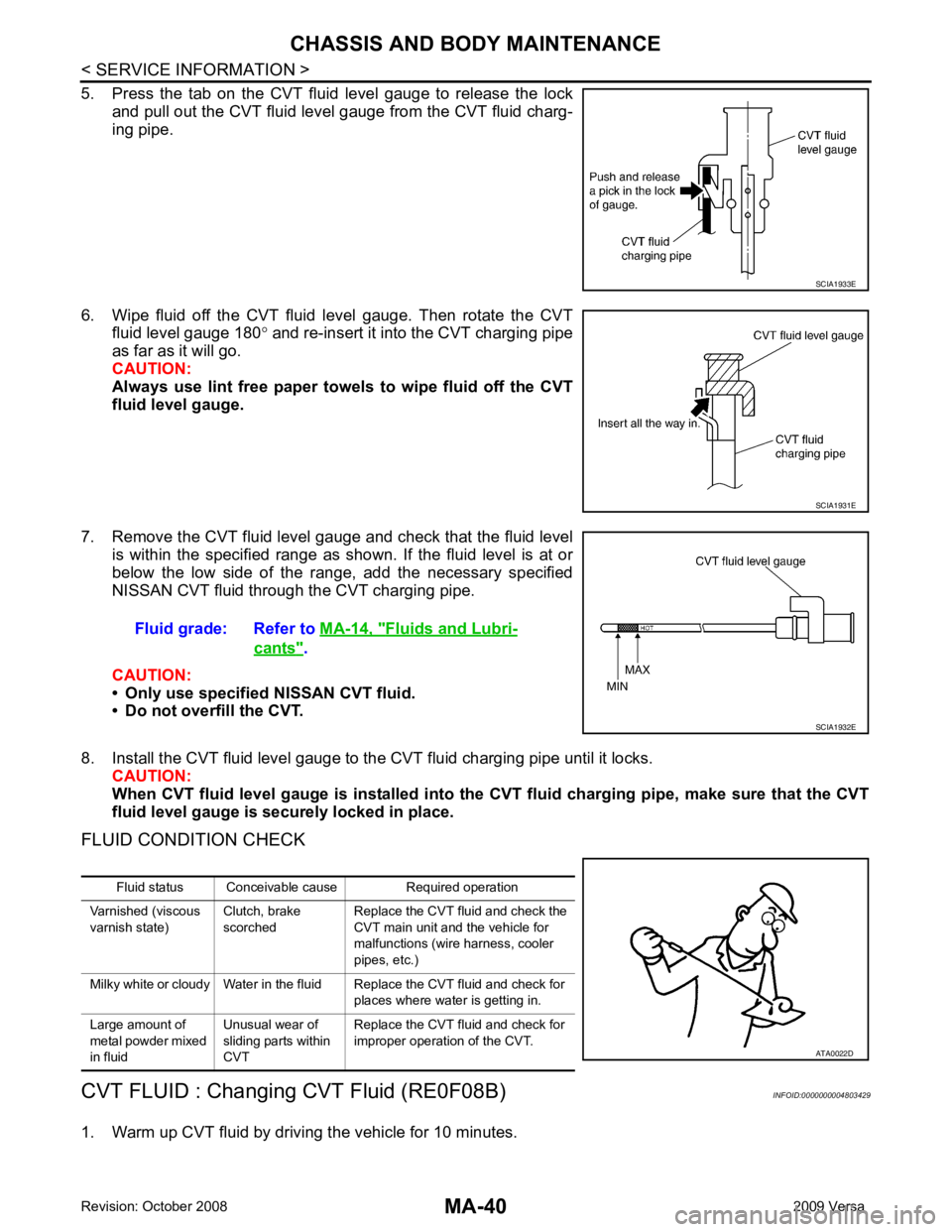
5. Press the tab on the CVT fluid level gauge to release the lock and pull out the CVT fluid level gauge from the CVT fluid charg-
ing pipe.
6. Wipe fluid off the CVT fluid level gauge. Then rotate the CVT fluid level gauge 180 ° and re-insert it into the CVT charging pipe
as far as it will go.
CAUTION:
Always use lint free paper towels to wipe fluid off the CVT
fluid level gauge.
7. Remove the CVT fluid level gauge and check that the fluid level is within the specified range as shown. If the fluid level is at or
below the low side of the range, add the necessary specified
NISSAN CVT fluid through the CVT charging pipe.
CAUTION:
• Only use specified NISSAN CVT fluid.
• Do not overfill the CVT.
8. Install the CVT fluid level gauge to the CVT fluid charging pipe until it locks. CAUTION:
When CVT fluid level gauge is in stalled into the CVT fluid charging pipe, make sure that the CVT
fluid level gauge is securely locked in place.
FLUID CONDITION CHECK
CVT FLUID : Changing CVT Fluid (RE0F08B) INFOID:0000000004803429
1. Warm up CVT fluid by driving the vehicle for 10 minutes. SCIA1933E
SCIA1931E
Fluid grade: Refer to
MA-14, " Fluids and Lubri-
cants " .
SCIA1932E
Fluid status Conceivable cause Required operation
Varnished (viscous
varnish state) Clutch, brake
scorched Replace the CVT fluid and check the
CVT main unit and the vehicle for
malfunctions (wire harness, cooler
pipes, etc.)
Milky white or cloudy Water in the fluid Replace the CVT fluid and check for places where water is getting in.
Large amount of
metal powder mixed
in fluid Unusual wear of
sliding parts within
CVT Replace the CVT fluid and check for
improper operation of the CVT. ATA0022D
Page 3787 of 4331
Disassembly and Assembly " .
CAUTION:
Do not reuse gasket.
M/T OIL : Checking M/T Oil (RS6F94R) INFOID:0000000004803425
OIL LEAKAGE AND OIL LEVEL
1. Make sure that oil is not leaking from transaxle or around it.
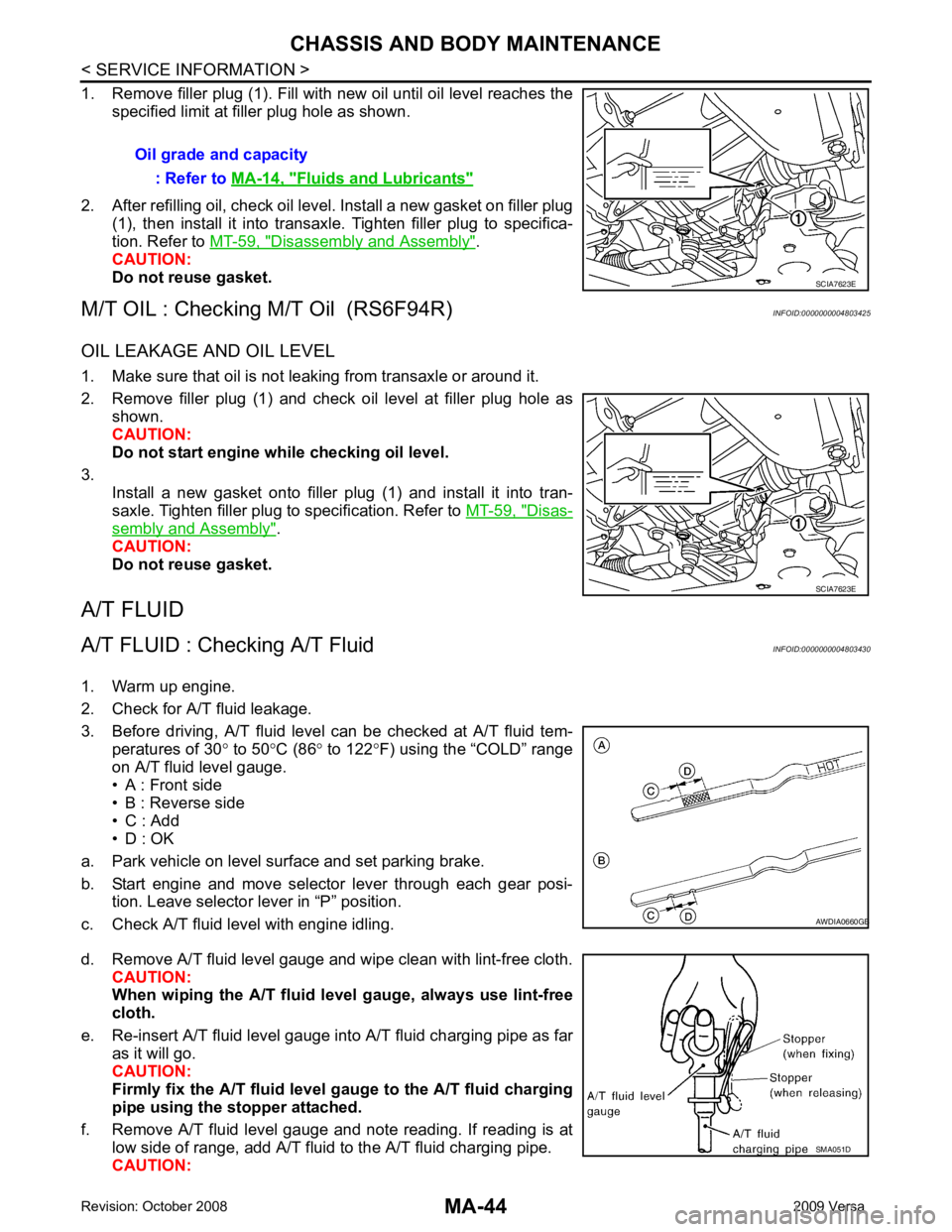
2. Remove filler plug (1) and check oil level at filler plug hole as shown.
CAUTION:
Do not start engine wh ile checking oil level.
3. Install a new gasket onto filler plug (1) and install it into tran-
saxle. Tighten filler plug to specification. Refer to MT-59, " Disas-
sembly and Assembly " .
CAUTION:
Do not reuse gasket.
A/T FLUID
A/T FLUID : Checking A/T Fluid INFOID:0000000004803430
1. Warm up engine.
2. Check for A/T fluid leakage.
3. Before driving, A/T fluid level can be checked at A/T fluid tem- peratures of 30 ° to 50 °C (86 ° to 122 °F) using the “COLD” range
on A/T fluid level gauge.
• A : Front side
• B : Reverse side
• C : Add
• D : OK
a. Park vehicle on level surface and set parking brake.
b. Start engine and move selector lever through each gear posi- tion. Leave selector lever in “P” position.
c. Check A/T fluid level with engine idling.
d. Remove A/T fluid level gauge and wipe clean with lint-free cloth. CAUTION:
When wiping the A/T fluid level gauge, always use lint-free
cloth.
e. Re-insert A/T fluid level gauge into A/T fluid charging pipe as far as it will go.
CAUTION:
Firmly fix the A/T fluid level ga uge to the A/T fluid charging
pipe using the stopper attached.
f. Remove A/T fluid level gauge and note reading. If reading is at low side of range, add A/T fluid to the A/T fluid charging pipe.
CAUTION: Oil grade and capacity
: Refer to MA-14, " Fluids and Lubricants "
SCIA7623E
B
Page 3789 of 4331
MA-46< SERVICE INFORMATION >
CHASSIS AND BODY MAINTENANCE
WHEELS : Rotation INFOID:0000000004683838
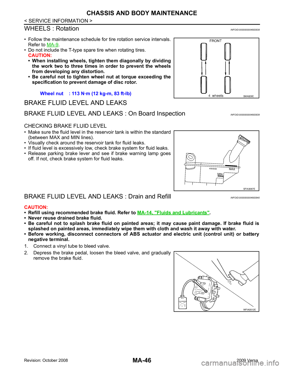
• Follow the maintenance schedule for tire rotation service intervals. Refer to MA-9 .
• Do not include the T-type spare tire when rotating tires.
CAUTION:
• When installing wheels, tighten them diagonally by dividing
the work two to three times in order to prevent the wheels
from developing any distortion.
• Be careful not to tighten wheel nut at torque exceeding the specification to prevent damage of disc rotor.
BRAKE FLUID LEVEL AND LEAKS
BRAKE FLUID LEVEL AND LEAK S : On Board Inspection INFOID:0000000004683839
CHECKING BRAKE FLUID LEVEL
• Make sure the fluid level in the reservoir tank is within the standard (between MAX and MIN lines).
• Visually check around the reservoir tank for fluid leaks.
• If fluid level is excessively low, check brake system for fluid leaks.
• Release parking brake lever and see if brake warning lamp goes off. If not, check brake system for fluid leaks.
BRAKE FLUID LEVEL AND LE AKS : Drain and Refill INFOID:0000000004683840
CAUTION:
• Refill using recommended brake fluid. Refer to MA-14, " Fluids and Lubricants " .
• Never reuse drained brake fluid.
• Be careful not to splash brake fluid on painted areas; it may cause paint damage. If brake fluid is
splashed on painted areas, immediately wipe th em with cloth and wash it away with water.
• Before working, disconnect connectors of ABS actua tor and electric unit (control unit) or battery
negative terminal.
1. Connect a vinyl tube to bleed valve.
2. Depress the brake pedal, loosen the bleed valve, and gradually remove the brake fluid.Wheel nut : 113 N·m (12 kg-m, 83 ft-lb) SMA829C
SFIA3067E
WFIA0512E
Page 3790 of 4331
CHASSIS AND BODY MAINTENANCE
MA-47
< SERVICE INFORMATION >
C
D E
F
G H
I
J
K
M A
B MA
N
O P
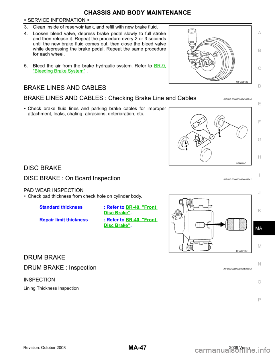
3. Clean inside of reservoir tank, and refill with new brake fluid.
4. Loosen bleed valve, depress brake pedal slowly to full stroke and then release it. Repeat the procedure every 2 or 3 seconds
until the new brake fluid comes out, then close the bleed valve
while depressing the brake pedal . Repeat the same procedure
for each wheel.
5. Bleed the air from the brake hydraulic system. Refer to BR-9," Bleeding Brake System " .
BRAKE LINES AND CABLES
BRAKE LINES AND CABLES : C hecking Brake Line and Cables INFOID:0000000004305214
• Check brake fluid lines and parking brake cables for improper attachment, leaks, chafing, abrasions, deterioration, etc.
DISC BRAKE
DISC BRAKE : On Board Inspection INFOID:0000000004683841
PAD WEAR INSPECTION • Check pad thickness from check hole on cylinder body.
DRUM BRAKE
DRUM BRAKE : Inspection INFOID:0000000004683843
INSPECTION
Lining Thickness Inspection WFIA0513E
SBR389C
Standard thickness : Refer to
BR-40, " Front
Disc Brake " .
Repair limit thickness : Refer to BR-40, " Front
Disc Brake " .
BRA0010D
Page 3791 of 4331
MA-48< SERVICE INFORMATION >
CHASSIS AND BODY MAINTENANCE
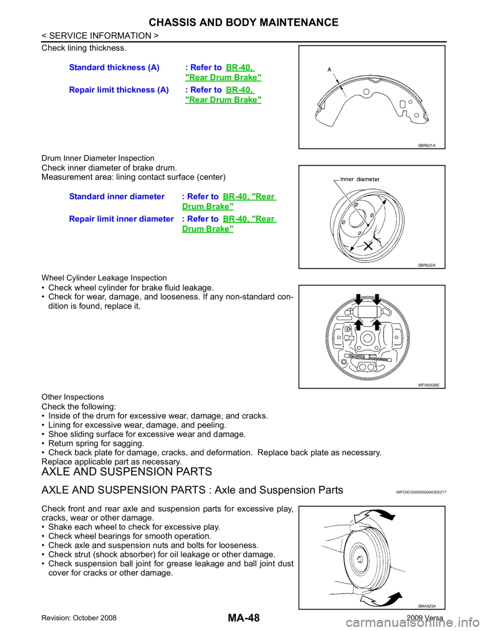
Check lining thickness.
Drum Inner Diameter Inspection
Check inner diameter of brake drum.
Measurement area: lining contact surface (center)
Wheel Cylinder Leakage Inspection
• Check wheel cylinder for brake fluid leakage.
• Check for wear, damage, and looseness. If any non-standard con-
dition is found, replace it.
Other Inspections
Check the following:
• Inside of the drum for excessive wear, damage, and cracks.
• Lining for excessive wear, damage, and peeling.
• Shoe sliding surface for excessive wear and damage.
• Return spring for sagging.
• Check back plate for damage, cracks, and deforma tion. Replace back plate as necessary.
Replace applicable part as necessary.
AXLE AND SUSPENSION PARTS
AXLE AND SUSPENSION PARTS : Axle and Suspension Parts INFOID:0000000004305217
Check front and rear axle and suspension parts for excessive play,
cracks, wear or other damage.
• Shake each wheel to check for excessive play.
• Check wheel bearings for smooth operation.
• Check axle and suspension nuts and bolts for looseness.
• Check strut (shock absorber) for oil leakage or other damage.
• Check suspension ball joint for grease leakage and ball joint dust cover for cracks or other damage. Standard thickness (A) : Refer to
BR-40, " Rear Drum Brake "
Repair limit thickness (A) : Refer to
BR-40, " Rear Drum Brake "
SBR021A
Standard inner diameter : Refer to
BR-40, " Rear
Drum Brake "
Repair limit inner diameter : Refer to
BR-40, " Rear
Drum Brake "
SBR022A
WFIA0528E
SMA525A
Page 4040 of 4331

PG
N
O P
Wiring Diagram Codes (Cell Codes)
INFOID:0000000004306667
Use the chart below to find out what each wiring diagram code stands for.
Refer to the wiring diagram code in the alphabetical index to find the location (page number) of each wiring
diagram. D4 D405 W/4 : Back door lock assembly C2 D413 B/1 : Rear window defogger (-)
D4 D406 W/2 : Back door request switch F3 D414 — : Body ground
E2 D407 W/2 : High mounted stop lamp Code Section Wiring Diagram Name
ABS BRC Anti-lock Brake System
A/C,M MTC Manual Air Conditioner
APPS1 EC Accelerator Pe dal Position Sensor
A/F EC Air Fuel Ratio Sensor 1
A/FH EC Air Fuel Ratio Sensor 1 Heater
APPS2 EC Accelerator Pe dal Position Sensor
APPS3 EC Accelerator Pe dal Position Sensor
ASC/BS EC ASCD Brake Switch
ASC/SW EC ASCD Steering Switch
ASCBOF EC ASCD Brake Switch
ASCIND EC ASCD Indicator
AT/IND DI A/T Indicator Lamp
AUDIO AV Audio
BACK/L LT Back-up Lamp
BA/FTS AT A/T Fluid Temperature Sensor and TCM Power Supply
B/DOOR BL Back Door Opener
BRK/SW EC Brake Switch
CAN AT CAN Communication Line
CAN CVT CAN Comm unication Line
CAN EC CAN Communication Line
CAN LAN CAN System
CHARGE SC Charging System
CHIME DI Warning Chime
COOL/F EC Cooling Fan Control
COMBSW LT Combination Switch
CVTIND DI CVT Indicator Lamp
D/LOCK BL Power Door Lock
DEF GW Rear Window Defogger
DTRL LT Headlamp - Wi th Daytime Light System
ECTS EC Engine Coolant Temperature Sensor
ENGSS AT Engine Speed Signal
EPS STC Electronic Controlled Power Steering
ETC1 EC Electric Throttle Control Function
ETC2 EC Throttle Control Motor Relay
ETC3 EC Throttle Control Motor
F/FOG LT Front Fog Lamp
F/PUMP EC Fuel Pump
FTS AT A/T Fluid Temperature Sensor
FTS CVT CVT Fluid Temperature Sensor Circuit
FTTS EC Fuel Tank Temperature Sensor
FUEL EC Fuel Ignition System Function
HEATER MTC Heater System