Page 2970 of 4331

EM
NP
O
COMPRESSION PRESSURE
Inspection INFOID:0000000004784276
1. Warm up engine thoroughly. Then, stop it.
2. Release fuel pressure. Refer to EC-498, " Inspection " .
3. Remove ignition coil and spark plug from each cylinder. Refer to EM-46, " Exploded View " .
4. Connect an engine tachometer (not required in use of CONSULT-III).
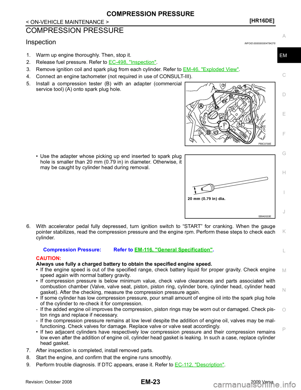
5. Install a compression tester (B) with an adapter (commercial service tool) (A) onto spark plug hole.
• Use the adapter whose picking up end inserted to spark plug hole is smaller than 20 mm (0.79 in) in diameter. Otherwise, it
may be caught by cylinder head during removal.
6. With accelerator pedal fully depressed, turn ignition switch to “START” for cranking. When the gauge pointer stabilizes, read the compression pressure and the engine rpm. Perform these steps to check each
cylinder.
CAUTION:
Always use fully a charged battery to obtain the specified engine speed.
• If the engine speed is out of the specified range, c heck battery liquid for proper gravity. Check engine
speed again with normal battery gravity.
• If compression pressure is below minimum value, check valve clearances and parts associated with combustion chamber (Valve, valve seat, piston, pi ston ring, cylinder bore, cylinder head, cylinder head
gasket). After the checking, measure the compression pressure again.
• If some cylinder has low compression pressure, pour small amount of engine oil into the spark plug hole
of the cylinder to re-check it for compression.
- If the added engine oil improves the compression, piston rings may be worn out or damaged. Check pis-
ton rings and replace if necessary.
- If the compression pressure remains at low level despite the addition of engine oil, valves may be mal- functioning. Check valves for damage. Replace valve or valve seat accordingly.
• If two adjacent cylinders have respectively low compression pressure and their compression remains low even after the addition of engine oil, cylinder head gasket is leaking. In such a case, replace cylinder
head gasket.
7. After inspection is completed, install removed parts.
8. Start the engine, and confirm that the engine runs smoothly.
9. Perform trouble diagnosis. If DTC appears, erase it. Refer to EC-112, " Description " . SBIA0533E
General Specification " .
Page 2993 of 4331
Exploded View " .
2. Remove ignition coil. CAUTION:
• Handle ignition coil car efully and avoid impacts.
• Never disassemble.
1. Ignition coil 2. Spark plug 3. PCV hose
4. Oil filler cap 5. Rocker cover 6. Gasket
7. Bracket 8. O-ring 9. PCV valve
10. PCV hose A: To air duct
Page 2994 of 4331
EM
NP
O
3. Remove spark plug using suitable tool.
CAUTION:
Never drop or shock it.
4. Remove ground cable (RH).
5. Support the bottom surface of engine using a trans mission jack, and then remove the engine mounting
bracket and insulator (RH). Refer to EM-88, " Exploded View " .
6. Remove fuel tube protector.
7. Disconnect PCV valve hose from PCV valve.
8. Remove oil filler cap.
9. Remove rocker cover. • Loosen bolts in reverse order shown.
NOTE:
13 and 14 shown are used to tighten the fuel tube protector.
10. Remove rocker cover gasket from rocker cover.
11. Use scraper to remove all traces of liquid gasket from cylinder head and front cover.
CAUTION:
Never scratch or damage the mating su rface when cleaning off old liquid gasket.
INSPECTION AFTER REMOVAL CAUTION:
• Never drop or shock spark plug.
• Checking and adjusting spar k plug gap is not required
between change intervals.
• If spark plug tip is covered with carbon, a spark plug cleaner may be used. SMA806CA
Page 3029 of 4331
1. Spark plug 2. Valve collet 3. Valve spring retainer
4. Valve spring 5. Valve spring seat 6. Valve oil seal
7. Valve guide (EXH) 8. Valve guide (INT) 9. Cylinder head
10. Valve seat (EXH) 11. Valve (EXH) 12. Valve seat (INT)
13. Valve (INT)
A. Refer to Installation procedure B. Refer to Installation procedure
Page 3030 of 4331
![NISSAN TIIDA 2009 Service Repair Manual CYLINDER HEAD
EM-83
< ON-VEHICLE REPAIR >
[HR16DE] C
D E
F
G H
I
J
K L
M A EM
NP
O
1. Remove spark plug using suitable tool.
2. Remove valve lifter. • Identify installation positions, and store them NISSAN TIIDA 2009 Service Repair Manual CYLINDER HEAD
EM-83
< ON-VEHICLE REPAIR >
[HR16DE] C
D E
F
G H
I
J
K L
M A EM
NP
O
1. Remove spark plug using suitable tool.
2. Remove valve lifter. • Identify installation positions, and store them](/manual-img/5/57398/w960_57398-3029.png)
CYLINDER HEAD
EM-83
< ON-VEHICLE REPAIR >
[HR16DE] C
D E
F
G H
I
J
K L
M A EM
NP
O
1. Remove spark plug using suitable tool.
2. Remove valve lifter. • Identify installation positions, and store them without mixing them up.
3. Remove valve collet. • Compress valve spring with Tool (A). Remove valve collet witha magnet tool (B).
CAUTION:
Be careful not to damage valve lifter holes.
4. Remove valve spring retainer and valve spring.
5. Push valve stem to combustion chamber side, and remove valve. • Identify installation positions, and store them without mixing them up.
6. Remove valve oil seal using Tool (A).
7. Remove valve spring seat.
8. Remove valve seat, if necessary. • Bore out old seat until it collapses. Boring s hould not continue beyond the bottom face of the seat
recess in cylinder head. Set the machine depth stop to ensure this.
CAUTION:
Never bore excessively to prevent cylinder head from scratching.
9. Remove valve guide, if necessary.
a. To remove valve guide, heat cylinder head to 110 to 130 °C (230
to 266 °F) by soaking in heated oil (A).
Tool number : KV10116200 (J-26336-B)
: KV10115900 (J-26336-20)
: KV10109220 ( — ) PBIC3727E
Tool number : KV10107902 (J-38959)
: KV10116100 ( — ) PBIC3728E
JPBIA0184ZZ
Page 3034 of 4331
![NISSAN TIIDA 2009 Service Repair Manual CYLINDER HEAD
EM-87
< ON-VEHICLE REPAIR >
[HR16DE] C
D E
F
G H
I
J
K L
M A EM
NP
O
d. Using suitable tool or valve seat grinder, finish seat to the speci-
fied dimensions. Refer to EM-119, " Cylinder NISSAN TIIDA 2009 Service Repair Manual CYLINDER HEAD
EM-87
< ON-VEHICLE REPAIR >
[HR16DE] C
D E
F
G H
I
J
K L
M A EM
NP
O
d. Using suitable tool or valve seat grinder, finish seat to the speci-
fied dimensions. Refer to EM-119, " Cylinder](/manual-img/5/57398/w960_57398-3033.png)
CYLINDER HEAD
EM-87
< ON-VEHICLE REPAIR >
[HR16DE] C
D E
F
G H
I
J
K L
M A EM
NP
O
d. Using suitable tool or valve seat grinder, finish seat to the speci-
fied dimensions. Refer to EM-119, " Cylinder Head " .
CAUTION:
When using the valve seat cutt er, firmly grip cutter handle
with both hands. Then, press on the contacting surface all
around the circumference to cu t in a single drive. Improper
pressure on with cutter or cu tting many different times may
result in stage valve seat.
e. Using compound, grind to adjust valve fitting.
f. Check again for normal contact. Refer to EM-82, " Disassembly and Assembly " .
3. Install valve oil seal. • Install with Tool (A) to match dimension as shown.
4. Install valve spring seat.
5. Install valve. • Install larger diameter to intake side.
6. Install valve spring. NOTE:
It can be installed in either direction.
7. Install valve spring retainer.
8. Install valve collet. • Compress valve spring with Tool (A). Install valve collet with amagnet hand (B).
CAUTION:
Be careful not to damage valve lifter holes.
• Tap valve stem edge lightly with a plastic hammer after instal-
lation to check its installed condition.
9. Install valve lifter.
10. Install spark plug with a suitable tool. SEM934C
Height “H” : 13.2 - 13.8 mm (0.520 - 0.543 in)
Tool number : KV10115600 (J-38958) PBIC3211J
Tool number : KV10116200 (J-26336-B)
: KV10115900 (J-26336-20)
: KV10109220 ( — ) PBIC3727E
Page 3041 of 4331
Exploded View " .
2. Remove exhaust manifold. Refer to EM-31, " Exploded View " .
3. Remove oil pan (upper). Refer to EM-42, " Component " .
4. Remove ignition coil, spark plug and rocker cover. Refer to EM-46, " Exploded View " .
5. Remove fuel injector and fuel tube. Refer to EM-34, " Exploded View " .
6. Remove timing chain. Refer to EM-49, " Exploded View " .
7. Remove camshaft. Refer to EM-58, " Exploded View " .
8. Remove cylinder head. Refer to EM-79, " Removal and Installation " .
Assembly INFOID:0000000004784312
Assembly is in the reverse order of disassembly.
Page 3064 of 4331

EM
NP
O
*: When engine is cold.
Spark Plug INFOID:0000000004784324
SPARK PLUG (PLATINUM-TIPPED TYPE) Unit: mm (in)
Exhaust Manifold INFOID:0000000004784325
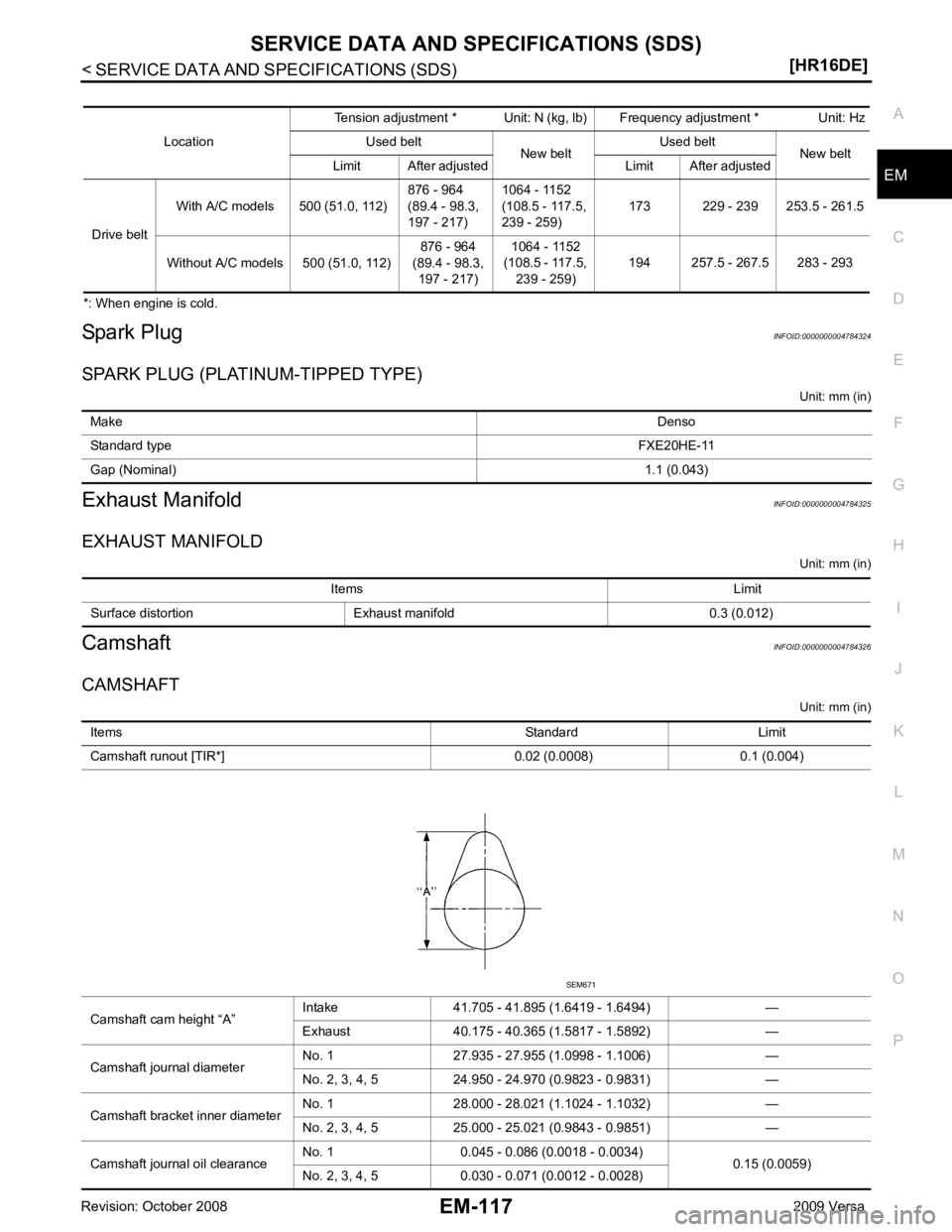
EXHAUST MANIFOLD Unit: mm (in)
Camshaft INFOID:0000000004784326
CAMSHAFT Unit: mm (in)
Location
Tension adjustment * Unit: N (kg, lb) Frequency adjustment * Unit: Hz
Used belt New beltUsed belt
New belt
Limit After adjusted Limit After adjusted
Drive belt With A/C models 500 (51.0, 112)
876 - 964
(89.4 - 98.3,
197 - 217) 1064 - 1152
(108.5 - 117.5,
239 - 259) 173 229 - 239 253.5 - 261.5
Without A/C models 500 (51.0, 112) 876 - 964
(89.4 - 98.3, 197 - 217) 1064 - 1152
(108.5 - 117.5, 239 - 259) 194 257.5 - 267.5 283 - 293Make
Denso
Standard type FXE20HE-11
Gap (Nominal) 1.1 (0.043)Items Limit
Surface distortion Exhaust manifold 0.3 (0.012) Items
Standard Limit
Camshaft runout [TIR*] 0.02 (0.0008) 0.1 (0.004)
Camshaft cam height “A” Intake 41.705 - 41.895 (1.6419 - 1.6494) —
Exhaust 40.175 - 40.365 (1.5817 - 1.5892) —
Camshaft journal diameter No. 1 27.935 - 27.955 (1.0998 - 1.1006) —
No. 2, 3, 4, 5 24.950 - 24.970 (0.9823 - 0.9831) —
Camshaft bracket inner diameter No. 1 28.000 - 28.021 (1.1024 - 1.1032) —
No. 2, 3, 4, 5 25.000 - 25.021 (0.9843 - 0.9851) —
Camshaft journal oil clearance No. 1 0.045 - 0.086 (0.0018 - 0.0034)
0.15 (0.0059)
No. 2, 3, 4, 5 0.030 - 0.071 (0.0012 - 0.0028)