Page 3074 of 4331
![NISSAN TIIDA 2009 Service Repair Manual PRECAUTIONS
EM-127
< SERVICE INFORMATION >
[MR18DE] C
D E
F
G H
I
J
K L
M A EM
NP
O
5. When the repair work is completed, return the ignition switch to the
″LOCK ″ position before c NISSAN TIIDA 2009 Service Repair Manual PRECAUTIONS
EM-127
< SERVICE INFORMATION >
[MR18DE] C
D E
F
G H
I
J
K L
M A EM
NP
O
5. When the repair work is completed, return the ignition switch to the
″LOCK ″ position before c](/manual-img/5/57398/w960_57398-3073.png)
PRECAUTIONS
EM-127
< SERVICE INFORMATION >
[MR18DE] C
D E
F
G H
I
J
K L
M A EM
NP
O
5. When the repair work is completed, return the ignition switch to the
″LOCK ″ position before connecting
the battery cables. (At this time, the steering lock mechanism will engage.)
6. Perform a self-diagnosis check of al l control units using CONSULT-III.
Precaution for Procedur e without Cowl Top Cover INFOID:0000000004307110
When performing the procedure after removing cowl top cover, cover
the lower end of windshield.
Precaution for Drain Coolant INFOID:0000000004307112
• Drain coolant when engine is cooled.
Precaution for Disco nnecting Fuel Piping INFOID:0000000004307113
• Before starting work, make sure no fire or spark producing items are in the work area.
• Release fuel pressure before disassembly.
• After disconnecting pipes, plug openings to stop fuel leakage.
Precaution for Removal and Disassembly INFOID:0000000004307114
• When instructed to use special service tools, use the spec ified tools. Always be careful to work safely, avoid
forceful or uninstructed operations.
• Exercise maximum care to avoid damage to mating or sliding surfaces.
• Cover openings of engine system with tape or the equiva lent, if necessary, to seal out foreign materials.
• Mark and arrange disassembly parts in an organized way for easy troubleshooting and assembly.
• When loosening nuts and bolts, as a basic rule, start with the one furthest outside, then the one diagonally opposite, and so on. If the order of loosening is specif ied, do exactly as specified. Power tools may be used
where noted in the step.
Precaution for Inspection, Repair and Replacement INFOID:0000000004307115
• Before repairing or replacing, thoroughly inspect parts. Inspect new replacement parts in the same way, and
replace if necessary.
Precaution for Assembly and Installation INFOID:0000000004307116
• Use torque wrench to tighten bolts or nuts to specification.
• When tightening nuts and bolts, as a basic rule, equally tighten in several different steps starting with the ones in center, then ones on inside and outside diagonally in this order. If the order of tightening is specified,
do exactly as specified.
• Replace with new gasket, packing, oil seal or O-ring.
• Thoroughly wash, clean, and air-blow each part. Carefully check oil or coolant passages for any restriction
and blockage.
• Avoid damaging sliding or mating surfaces. Completely remove foreign materials such as cloth lint or dust. Before assembly, oil sliding surfaces well.
• Release air within route after draining coolant.
• Before starting engine, apply fuel pressure to fuel lines with turning ignition switch ON (with engine stopped). Then make sure that there are no leaks at fuel line connections.
• After repairing, start engine and increase engine speed to check coolant, fuel, oil, and exhaust systems for leakage. PIIB3706J
Page 3079 of 4331
EM-132< SERVICE INFORMATION >
[MR18DE]
PREPARATION
Commercial Service Tool INFOID:0000000004307120
KV10109300
( — )
Pulley holder Removing and installing crankshaft pulley
KV10111800
( — )
Valve guide drift Removing and installing valve guide
Tool number
(Kent-Moore No.)
Tool name DescriptionNT628
PBIC4012E
(Kent-Moore No.)
Tool name Description
Power tool Loosening bolts and nuts
Spark plug wrench Removing and installing spark plug
Valve seat cutter set Finishing valve seat dimensions
Piston ring expander Removing and installing piston ring PBIC0190E
PBIC2982E
NT048
NT030
Page 3100 of 4331
EM
NP
O
IGNITION COIL, SPARK
PLUG AND ROCKER COVER
Component INFOID:0000000004307138
Removal and Installation INFOID:0000000004307139
REMOVAL 1. Remove intake manifold. Refer to EM-141 .
2. Remove ignition coil. CAUTION:
• Handle ignition coil car efully and avoid impacts.
• Never disassemble.
1. PCV hose 2. Rocker cover 3. Spark plug
4. Ignition coil 5. PCV hose 6. PCV valve
7. O-ring 8. Gasket
A. To air duct B. Refer to EM-153 . C. To intake manifold
Page 3101 of 4331
EM-154< SERVICE INFORMATION >
[MR18DE]
IGNITION COIL, SPARK PLUG AND ROCKER COVER
3. Remove spark plug using suitable tool. CAUTION:
Never drop or shock it.
4. Remove rocker cover. • Loosen bolts in reverse order as shown.
• Engine front
INSPECTION AFTER REMOVAL
CAUTION:
• Never drop or shock spark plug.
• Checking and adjusting spar k plug gap is not required
between change intervals.
• If spark plug tip is covered with car bon, a spark plug cleaner may be used.
• Never use wire brush for cleaning spark plug.
INSTALLATION
1. Install the rocker cover gasket to the rocker cover. PBIC3871E
PBIC3151J
SMA806CA
Cleaner air pressure
: Less than 588 kPa (5.88 bar, 6 kg/cm 2
, 85 psi)
Cleaning time : Less than 20 seconds SMA773C
Page 3102 of 4331
IGNITION COIL, SPARK
PLUG AND ROCKER COVER
EM-155
< SERVICE INFORMATION >
[MR18DE] C
D E
F
G H
I
J
K L
M A EM
NP
O
2. Install rocker cover.
• Tighten bolts in two steps separately in numerical order asshown.
• Engine front
CAUTION:
Check if rocker cover gasket is not dropped from the instal-
lation groove of rocker cover.
3. Install spark plug using suitable tool.
CAUTION:
Never drop or shock it.
4. Install ignition coil. CAUTION:
• Handle it carefully and avoid impacts.
• Never disassemble.
5. Install intake manifold. Refer to EM-141 .
1st step : 1.96 N·m (0.20 kg-m, 17 in-lb)
2nd step : 8.33 N·m (0.85 kg-m, 73 in-lb) PBIC3151J
Make : DENSO
Part number : FXE20HR11
Gap (nominal) : 1.1 mm (0.043 in) PBIC3871E
Page 3132 of 4331

EM
NP
O
CYLINDER HEAD
On-Vehicle Service INFOID:0000000004307150
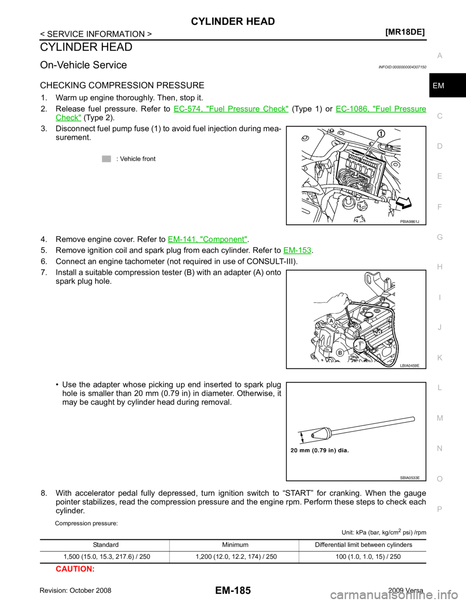
CHECKING COMPRESSION PRESSURE 1. Warm up engine thoroughly. Then, stop it.
2. Release fuel pressure. Refer to EC-574, " Fuel Pressure Check " (Type 1) or
EC-1086, " Fuel Pressure
Check " (Type 2).
3. Disconnect fuel pump fuse (1) to avoid fuel injection during mea- surement.
4. Remove engine cover. Refer to EM-141, " Component " .
5. Remove ignition coil and spark plug from each cylinder. Refer to EM-153 .
6. Connect an engine tachometer (not required in use of CONSULT-III).
7. Install a suitable compression tester (B) with an adapter (A) onto spark plug hole.
• Use the adapter whose picking up end inserted to spark plug hole is smaller than 20 mm (0.79 in) in diameter. Otherwise, it
may be caught by cylinder head during removal.
8. With accelerator pedal fully depressed, turn ignition switch to “START” for cranking. When the gauge pointer stabilizes, read the compression pressure and the engine rpm. Perform these steps to check each
cylinder.
Compression pressure: Unit: kPa (bar, kg/cm2
psi) /rpm
CAUTION: : Vehicle front
LBIA0459E
SBIA0533E
Page 3136 of 4331

EM
NP
O
Disassembly and Assembly
INFOID:0000000004307154
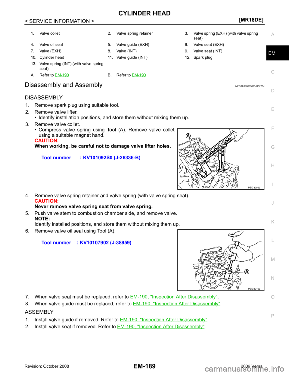
DISASSEMBLY 1. Remove spark plug using suitable tool.
2. Remove valve lifter. • Identify installation positions, and store them without mixing them up.
3. Remove valve collet. • Compress valve spring using Tool (A). Remove valve collet
using a suitable magnet hand.
CAUTION:
When working, be careful not to damage valve lifter holes.
4. Remove valve spring retainer and valve spring (with valve spring seat). CAUTION:
Never remove valve spring seat from valve spring.
5. Push valve stem to combustion chamber side, and remove valve. NOTE:
Identify installed positions, and st ore them without mixing them up.
6. Remove valve oil seal using Tool (A).
7. When valve seat must be replaced, refer to EM-190, " Inspection After Disassembly " .
8. When valve guide must be replaced, refer to EM-190, " Inspection After Disassembly " .
ASSEMBLY 1. Install valve guide if removed. Refer to EM-190, " Inspection After Disassembly " .
2. Install valve seat if removed. Refer to EM-190, " Inspection After Disassembly " .
1. Valve collet 2. Valve spring retainer 3. Valve spring (EXH) (with valve spring
seat)
4. Valve oil seal 5. Valve guide (EXH) 6. Valve seat (EXH)
7. Valve (EXH) 8. Valve (INT) 9. Valve seat (INT)
10. Cylinder head 11. Valve guide (INT) 12. Spark plug
13. Valve spring (INT ) (with valve spring
seat)
A. Refer to EM-190 B. Refer to
EM-190
Page 3137 of 4331
![NISSAN TIIDA 2009 Service Repair Manual EM-190< SERVICE INFORMATION >
[MR18DE]
CYLINDER HEAD
3. Install valve oil seal. • Install with a valve oil seal using Tool (A) to match dimensionas shown.
NOTE:
Dimension (H) is height NISSAN TIIDA 2009 Service Repair Manual EM-190< SERVICE INFORMATION >
[MR18DE]
CYLINDER HEAD
3. Install valve oil seal. • Install with a valve oil seal using Tool (A) to match dimensionas shown.
NOTE:
Dimension (H) is height](/manual-img/5/57398/w960_57398-3136.png)
EM-190< SERVICE INFORMATION >
[MR18DE]
CYLINDER HEAD
3. Install valve oil seal. • Install with a valve oil seal using Tool (A) to match dimensionas shown.
NOTE:
Dimension (H) is height that measured before installing valve
spring (with valve spring seat).
4. Install valve. • Install larger diameter to intake side.
5. Install valve spring (with valve spring seat). • Install smaller pitch (valve spring seat side) to cylinder head
side (B).
• Confirm identification color (A) of valve spring.
6. Install valve spring retainer.
7. Install valve collet. • Compress valve spring using Tool (A). Install valve collet with a magnet hand.
CAUTION:
When working, be careful not to damage valve lifter holes.
• Tap valve stem edge lightly with a plastic hammer after instal- lation to check its installed condition.
8. Install valve lifter. • Install it in the original position.
9. Install spark plug using suitable tool.
Inspection After Disassembly INFOID:0000000004307155
VALVE DIMENSIONS
• Check dimensions of each valve. For dimensions, refer to EM-227, " Standard and Limit " .
• If dimensions are out of the standard, replace valve.
VALVE GUIDE CLEARANCE
Valve Stem Diameter Tool number : KV10115600 (J-38958)
Height (H) : 15.1 - 15.7 mm (0.594 - 0.618 in) PBIC3211J
1 : Valve spring seat (Do not remove from valve spring.)
Intake : White
Exhaust : Orange PBIC3462J
Tool number : KV101092S0 (J-26336 B)
PBIC3209J