2009 NISSAN TIIDA power steering
[x] Cancel search: power steeringPage 1415 of 4331
![NISSAN TIIDA 2009 Service Repair Manual AIR CONDITIONING CUT CONTROL
EC-59
< FUNCTION DIAGNOSIS >
[HR16DE] C
D E
F
G H
I
J
K L
M A EC
NP
O
• When operating power steering during low engine speed or low vehicle speed.
• When engine speed NISSAN TIIDA 2009 Service Repair Manual AIR CONDITIONING CUT CONTROL
EC-59
< FUNCTION DIAGNOSIS >
[HR16DE] C
D E
F
G H
I
J
K L
M A EC
NP
O
• When operating power steering during low engine speed or low vehicle speed.
• When engine speed](/manual-img/5/57398/w960_57398-1414.png)
AIR CONDITIONING CUT CONTROL
EC-59
< FUNCTION DIAGNOSIS >
[HR16DE] C
D E
F
G H
I
J
K L
M A EC
NP
O
• When operating power steering during low engine speed or low vehicle speed.
• When engine speed is excessively low.
• When refrigerant pressure is excessively low or high.
Component Parts Location INFOID:0000000004780020
1. Ignition coil (with power transistor) and spark plug 2. Intake valve timing control solenoid
valve 3. Refrigerant pressure sensor
4. Knock sensor 5. Fuel injector 6. Cooling fan motor
7. Camshaft position sensor (PHASE) 8. IPDM E/R 9. ECM
10. Mass air flow sensor (with intake air temperature sensor) 11. Engine coolant temperature sensor 12. Electric throttle control actuator
(with built in throttle position sensor
and throttle control motor)
13. EVAP canister purge volume control solenoid valve PBIB2939E
Page 1463 of 4331

EC
NP
O
HO2S2 (B1) V
• The signal voltage of the heated oxygen sensor 2 is
displayed.
HO2S2 MNTR(B1) RICH/
LEAN • Display of heated oxygen sensor 2 signal:
RICH: means the amount of oxygen after three way
catalyst is relatively small.
LEAN: means the amount of oxygen after three way
catalyst is relatively large. • When the engine is stopped, a certain
value is indicated.
VHCL SPEED SE km/h or
mph • The vehicle speed computed from the vehicle speed
signal sent from combination meter is displayed.
BATTERY VOLT V • The power supply voltage of ECM is displayed.
ACCEL SEN 1 V• The accelerator pedal position sensor signal voltage is
displayed. • ACCEL SEN 2 signal is converted by
ECM internally. Thus, it differs from
ECM terminal voltage signal.
ACCEL SEN 2
TP SEN 1-B1 V• The throttle position sensor signal voltage is dis-
played. • TP SEN 2-B1 signal is converted by
ECM internally. Thus, it differs from
ECM terminal voltage signal.
TP SEN 2-B1
FUEL T/TMP SE °C or °F • The fuel temperature (determined by the signal volt-
age of the fuel tank temperature sensor) is displayed.
INT/A TEMP SE °C or °F • The intake air temperature (determined by the signal
voltage of the intake air temperature sensor) is indicat-
ed.
EVAP SYS PRES V • The signal voltage of EVAP control system pressure
sensor is displayed.
FUEL LEVEL SE V • The signal voltage of the fuel level sensor is displayed.
START SIGNAL ON/OFF • Indicates start signal status [ON/OFF] computed by
the ECM according to the signals of engine speed and
battery voltage. • After starting the engine, [OFF] is dis-
played regardless of the starter sig-
nal.
CLSD THL POS ON/OFF • Indicates idle position [ON/OFF] computed by ECM
according to the accelerator pedal position sensor sig-
nal.
AIR COND SIG ON/OFF • Indicates [ON/OFF] condition of the air conditioner
switch determined by the air conditioner ON signal.
P/N POSI SW ON/OFF • Indicates [ON/OFF] condit
ion from the park/neutral
position (PNP) switch signal.
PW/ST SIGNAL ON/OFF • [ON/OFF] condition of the power steering system (de-
termined by the signal sent from EPS control unit) is
indicated.
LOAD SIGNAL ON/OFF • Indicates [ON/OFF] condition from the electrical load
signal.
ON: Rear window defogger switch is ON and/or light-
ing switch is in 2nd position.
OFF: Both rear window defogger switch and lighting
switch are OFF.
IGNITION SW ON/OFF • Indicates [ON/OFF] condition from ignition switch sig-
nal.
HEATER FAN SW ON/OFF • Indicates [ON/OFF] condition from the heater fan
switch signal.
BRAKE SW ON/OFF • Indicates [ON/OFF] condition from the stop lamp
switch signal.
INJ PULSE-B1 msec • Indicates the actual fuel injection pulse width compen-
sated by ECM according to the input signals. • When the engine is stopped, a certain
computed value is indicated.
IGN TIMING BTDC • Indicates the ignition timing computed by ECM ac-
cording to the input signals. • When the engine is stopped, a certain
value is indicated.
CAL/LD VALUE % • “Calculated load value” indicates the value of the cur-
rent air flow divided by peak air flow.
Monitored item Unit Description Remarks
Page 1705 of 4331

EC
NP
O
P0506 ISC SYSTEM
Description INFOID:0000000004780224
The ECM controls the engine idle speed to a specified leve l through the fine adjustment of the air, which is let
into the intake manifold, by operating the electric thrott le control actuator. The operating of the throttle valve is
varied to allow for optimum control of the engine idli ng speed. The crankshaft position sensor (POS) detects
the actual engine speed and sends a signal to the ECM.
The ECM controls the electric throttle control actuator so that the engine speed coincides with the target value
memorized in the ECM. The target engine speed is t he lowest speed at which the engine can operate steadily.
The optimum value stored in the ECM is determined by taking into consideration various engine conditions,
such as during warming up, deceleration, and engine load (air conditioner, power steering and cooling fan
operation, etc.).
DTC Logic INFOID:0000000004780225
DTC DETECTION LOGIC NOTE:
If DTC P0506 is displayed with ot her DTC, first perform the trouble diagnosis for the other DTC.
DTC CONFIRMATION PROCEDURE IDLE AIR VOLUME LEARNING :
Special Repair Requirement " , before conducting DTC Confirmation Procedure.
TESTING CONDITION:
• Before performing the following procedure, confirm that battery voltage is more than 11 V at idle.
• Always perform the test at a temperature above −10 °C(14 °F).
>> GO TO 2. YES >> Go to
EC-349, " Diagnosis Procedure " .
NO >> INSPECTION END
Diagnosis Procedure INFOID:0000000004780226YES >> Discover air leak location and repair.
NO >> GO TO 2.
Page 1707 of 4331

EC
NP
O
P0507 ISC SYSTEM
Description INFOID:0000000004780227
The ECM controls the engine idle speed to a specified leve l through the fine adjustment of the air, which is let
into the intake manifold, by operating the electric thrott le control actuator. The operating of the throttle valve is
varied to allow for optimum control of the engine idli ng speed. The crankshaft position sensor (POS) detects
the actual engine speed and sends a signal to the ECM.
The ECM controls the electric throttle control actuator so that the engine speed coincides with the target value
memorized in the ECM. The target engine speed is t he lowest speed at which the engine can operate steadily.
The optimum value stored in the ECM is determined by taking into consideration various engine conditions,
such as during warming up, deceleration, and engine load (air conditioner, power steering and cooling fan
operation, etc.).
DTC Logic INFOID:0000000004780228
DTC DETECTION LOGIC NOTE:
If DTC P0507 is displayed with ot her DTC, first perform the trouble diagnosis for the other DTC.
DTC CONFIRMATION PROCEDURE IDLE AIR VOLUME LEARNING :
Special Repair Requirement " , before conducting DTC Confirmation Procedure.
TESTING CONDITION:
• Before performing the following procedure, confirm that battery voltage is more than 11 V at idle.
• Always perform the test at a temperature above −10 °C(14 °F).
>> GO TO 2. YES >> Go to
EC-351, " Diagnosis Procedure " .
NO >> INSPECTION END
Diagnosis Procedure INFOID:0000000004780229YES >> GO TO 2.
NO >> Repair or replace.
Page 1714 of 4331

YES >> Go to
EC-359, " Diagnosis Procedure " .
NO >> INSPECTION END DTC No. Trouble diagnosis name DTC detecting condition Possible cause
P0643 Sensor power supply
circuit short ECM detects a voltage of power source
for sensor is excessively low or high. • Harness or connectors
(APP sensor 1 circuit is shorted.)
(TP sensor circuit is shorted.)
(Battery current sensor circuit is shorted.)
(PSP sensor circuit is shorted.)
[Camshaft position sens or (PHASE) circuit is
shorted.]
• Accelerator pedal position sensor
• Throttle position sensor
• Battery current sensor
• Power steering pressure sensor
• Camshaft position sensor (PHASE)
Page 1875 of 4331

EC
NP
O
*1: This sensor is not used to control the engine system under normal conditions.
*2: This signal is sent to the ECM through CAN communication line.
*3: ECM determines the start signal status by the signals of engine speed and battery voltage.
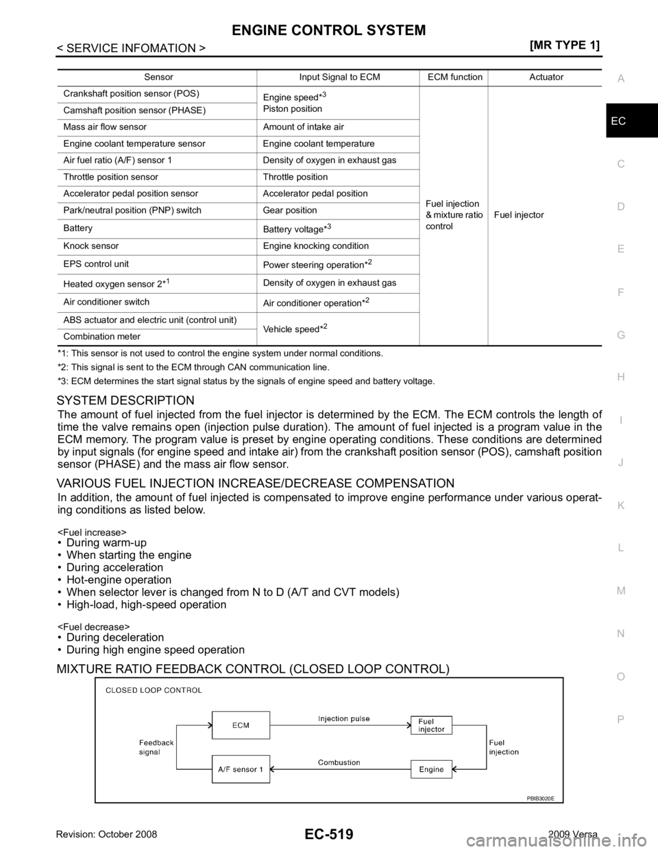
SYSTEM DESCRIPTION The amount of fuel injected from the fuel injector is determined by the ECM. The ECM controls the length of
time the valve remains open (injection pulse duration). T he amount of fuel injected is a program value in the
ECM memory. The program value is preset by engi ne operating conditions. These conditions are determined
by input signals (for engine speed and intake air) from t he crankshaft position sensor (POS), camshaft position
sensor (PHASE) and the mass air flow sensor.
VARIOUS FUEL INJECTION INCREASE/DECREASE COMPENSATION In addition, the amount of fuel injected is compens ated to improve engine performance under various operat-
ing conditions as listed below.
• During warm-up
• When starting the engine
• During acceleration
• Hot-engine operation
• When selector lever is changed from N to D (A/T and CVT models)
• High-load, high-speed operation
• During deceleration
• During high engine speed operation
MIXTURE RATIO FEEDBACK CONTROL (CLOSED LOOP CONTROL) Sensor Input Signal to ECM ECM function Actuator
Crankshaft position sensor (POS) Engine speed*3
Piston position
Fuel injection
& mixture ratio
control Fuel injector
Camshaft position sensor (PHASE)
Mass air flow sensor Amount of intake air
Engine coolant temperature sensor Engine coolant temperature
Air fuel ratio (A/F) sensor 1 Density of oxygen in exhaust gas
Throttle position sensor Throttle position
Accelerator pedal position sensor Accelerator pedal position
Park/neutral position (PNP) switch Gear position
Battery Battery voltage*3
Knock sensor Engine knocking condition
EPS control unit Power steering operation*2
Heated oxygen sensor 2* 1
Density of oxygen in exhaust gas
Air conditioner switch Air conditioner operation*2
ABS actuator and electric unit (control unit) Vehicle speed*2
Combination meter
Page 1879 of 4331

EC
NP
O
AIR CONDITIONING
CUT CONTROL
Input/Output Signal Chart INFOID:0000000004537023
*1: This signal is sent to the ECM through CAN communication line.
*2: ECM determines the start signal status by the signals of engine speed and battery voltage.
System Description INFOID:0000000004537024
This system improves engine operation when the air conditioner is used.
Under the following conditions, the air conditioner is turned off.
• When the accelerator pedal is fully depressed.
• When cranking the engine.
• At high engine speeds.
• When the engine coolant temperature becomes excessively high.
• When operating power steering during low engine speed or low vehicle speed.
• When engine speed is excessively low.
• When refrigerant pressure is excessively low or high. Sensor Input Signal to ECM ECM function Actuator
Air conditioner switch Air conditioner ON signal*1
Air conditioner
cut control Air conditioner relay
Accelerator pedal position sensor Accelerator pedal position
Crankshaft position sensor (POS)
Camshaft position sensor (PHASE) Engine speed*
2
Engine coolant temperature sensor Engine coolant temperature
Battery Battery voltage*2
Refrigerant pressure sensor Refrigerant pressure
EPS control unit Power steering operation*1
ABS actuator and electric unit (control unit) Vehicle speed*1
Combination meter
Page 1959 of 4331
![NISSAN TIIDA 2009 Service Repair Manual EC
NP
O
: Average voltage for pulse signal (Actual pulse signal can be confirmed by oscilloscope.) 94 R ASCD steering switch
[Ignition switch: ON]
• ASCD steering switch: OFF Approximately 4V
[Ignit NISSAN TIIDA 2009 Service Repair Manual EC
NP
O
: Average voltage for pulse signal (Actual pulse signal can be confirmed by oscilloscope.) 94 R ASCD steering switch
[Ignition switch: ON]
• ASCD steering switch: OFF Approximately 4V
[Ignit](/manual-img/5/57398/w960_57398-1958.png)
EC
NP
O
: Average voltage for pulse signal (Actual pulse signal can be confirmed by oscilloscope.) 94 R ASCD steering switch
[Ignition switch: ON]
• ASCD steering switch: OFF Approximately 4V
[Ignition switch: ON]
• MAIN switch: Pressed Approximately 0V
[Ignition switch: ON]
• CANCEL switch: Pressed Approximately 1V
[Ignition switch: ON]
• RESUME/ACCELERATE switch: Pressed Approximately 3V
[Ignition switch: ON]
• SET/COAST switch: Pressed Approximately 2V
95 B Sensor ground
(ASCD steering switch) [Engine is running]
• Warm-up condition
• Idle speed Approximately 0V
99 R Stop lamp switch [Ignition switch: OFF]
• Brake pedal: Fully released Approximately 0V
[Ignition switch: OFF]
• Brake pedal: Slightly depressed BATTERY VOLTAGE
(11 - 14V)
100 G ASCD brake switch [Ignition switch: ON]
• Brake pedal: Slightly depressed (A/T, CVT)
• Brake pedal and/or clutch pedal: Slightly de-
pressed (M/T) Approximately 0V
[Ignition switch: ON]
• Brake pedal: Fully released (A/T, CVT)
• Brake pedal and clutch pedal: Fully re-
leased (M/T) BATTTERY VOLTAGE
(11 - 14V)
102 SB Sensor power supply
(Accelerator pedal position
sensor 2) [Ignition switch: ON]
Approximately 5V
103 GR Accelerator pedal position
sensor 2 [Ignition switch: ON]
• Engine stopped
• Accelerator pedal: Fully released 0.3 - 0.6V
[Ignition switch: ON]
• Engine stopped
• Accelerator pedal: Fully depressed 1.95 - 2.4V
104 Y Sensor ground
(Accelerator pedal position
sensor 2) [Engine is running]
• Warm-up condition
• Idle speed Approximately 0V
105 G Power supply for ECM [Ignition switch: ON]BATTERY VOLTAGE
(11 - 14V)
106 P Sensor power supply
(Accelerator pedal position
sensor 1) [Ignition switch: ON]
Approximately 5V
108 B ECM ground [Engine is running]
• Idle speed Body ground
110 G Accelerator pedal position
sensor 1 [Ignition switch: ON]
• Engine stopped
• Accelerator pedal: Fully released 0.6 - 0.9V
[Ignition switch: ON]
• Engine stopped
• Accelerator pedal: Fully depressed 3.9 - 4.7V
111 R Sensor ground
(Accelerator pedal position
sensor 1) [Engine is running]
• Warm-up condition
• Idle speed Approximately 0V
TERMI-
NAL
NO. WIRE
COLOR ITEM CONDITION DATA (DC Voltage)