2009 NISSAN TIIDA power steering
[x] Cancel search: power steeringPage 2747 of 4331

EC
NP
O
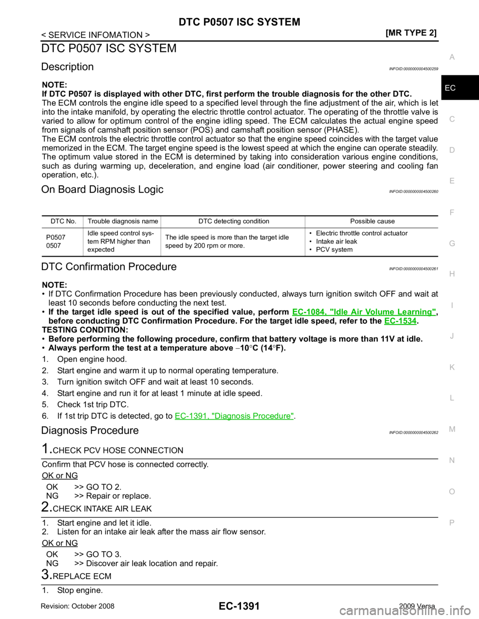
DTC P0507 ISC SYSTEM
Description INFOID:0000000004500259
NOTE:
If DTC P0507 is displayed with ot her DTC, first perform the trouble diagnosis for the other DTC.
The ECM controls the engine idle speed to a specified leve l through the fine adjustment of the air, which is let
into the intake manifold, by operating the electric thrott le control actuator. The operating of the throttle valve is
varied to allow for optimum control of the engine id ling speed. The ECM calculates the actual engine speed
from signals of camshaft position sensor (POS) and camshaft position sensor (PHASE).
The ECM controls the electric throttle control actuator so that the engine speed coincides with the target value
memorized in the ECM. The target engine speed is t he lowest speed at which the engine can operate steadily.
The optimum value stored in the ECM is determined by taking into consideration various engine conditions,
such as during warming up, deceleration, and engine load (air conditioner, power steering and cooling fan
operation, etc.).
On Board Diagnosis Logic INFOID:0000000004500260
DTC Confirmation Procedure INFOID:0000000004500261
NOTE:
• If DTC Confirmation Procedure has been previously conduc ted, always turn ignition switch OFF and wait at
least 10 seconds before conducting the next test.
• If the target idle speed is out of the specified value, perform EC-1084, " Idle Air Volume Learning " ,
before conducting DTC Confirmation Procedure. For the target idle speed, refer to the EC-1534 .
TESTING CONDITION:
• Before performing the following procedure, confirm that battery voltage is more than 11V at idle.
• Always perform the test at a temperature above −10 °C (14 °F).
1. Open engine hood.
2. Start engine and warm it up to normal operating temperature.
3. Turn ignition switch OFF and wait at least 10 seconds.
4. Start engine and run it for at least 1 minute at idle speed.
5. Check 1st trip DTC.
6. If 1st trip DTC is detected, go to EC-1391, " Diagnosis Procedure " .
Diagnosis Procedure INFOID:0000000004500262OK >> GO TO 2.
NG >> Repair or replace. OK >> GO TO 3.
NG >> Discover air leak location and repair.
Page 2783 of 4331
![NISSAN TIIDA 2009 Service Repair Manual DTC P1564 ASCD STEERING SWITCH
EC-1427
< SERVICE INFOMATION >
[MR TYPE 2] C
D E
F
G H
I
J
K L
M A EC
NP
O
Without CONSULT-III
1. Turn ignition switch ON.
2. Check voltage between ECM terminal 94 and NISSAN TIIDA 2009 Service Repair Manual DTC P1564 ASCD STEERING SWITCH
EC-1427
< SERVICE INFOMATION >
[MR TYPE 2] C
D E
F
G H
I
J
K L
M A EC
NP
O
Without CONSULT-III
1. Turn ignition switch ON.
2. Check voltage between ECM terminal 94 and](/manual-img/5/57398/w960_57398-2782.png)
DTC P1564 ASCD STEERING SWITCH
EC-1427
< SERVICE INFOMATION >
[MR TYPE 2] C
D E
F
G H
I
J
K L
M A EC
NP
O
Without CONSULT-III
1. Turn ignition switch ON.
2. Check voltage between ECM terminal 94 and ground with press- ing each button.
OK or NG OK >> GO TO 8.
NG >> GO TO 3. 3.
CHECK ASCD STEERING SWITCH GRO UND CIRCUIT FOR OPEN AND SHORT
1. Turn ignition switch OFF.
2. Disconnect combination switch harness connector M31.
3. Disconnect ECM harness connector.
4. Check harness continuity between combinati on switch terminal 15 and ECM terminal 95.
Refer to Wiring Diagram.
5. Also check harness for short to ground or short to power.
OK or NG OK >> GO TO 5.
NG >> GO TO 4. 4.
DETECT MALFUNCTIONING PART
Check the following.
• Harness connectors M69, E7
• Combination switch (spiral cable)
• Harness for open and short between ECM and combination switch
>> Repair open circuit or short to ground or short to power in harness or connectors. 5.
CHECK ASCD STEERING SWITCH INPUT S IGNAL CIRCUIT FOR OPEN AND SHORT
1. Check harness continuity between ECM terminal 94 and combination switch terminal 14. Refer to Wiring Diagram.
2. Also check harness for short to ground and short to power.
OK or NG RESUME/AC-
CELERATE
switch RESUME/ACC SW
Pressed ON
Released OFF
SET/COAST
switch SET SW Pressed ON
Released OFF
Switch Monitor item Condition Indication Switch Condition Voltage [V]
MAIN switch Pressed Approx. 0
Released Approx. 4.0
CANCEL switch Pressed Approx. 1.0
Released Approx. 4.0
RESUME/ACCELER-
ATE switch Pressed Approx. 3.0
Released Approx. 4.0
SET/COAST switch Pressed Approx. 2.0
Released Approx. 4.0 PBIB3343E
Continuity should exist.
Continuity should exist.
Page 2784 of 4331
![NISSAN TIIDA 2009 Service Repair Manual EC-1428< SERVICE INFOMATION >
[MR TYPE 2]
DTC P1564 ASCD STEERING SWITCH
OK >> GO TO 7.
NG >> GO TO 6. 6.
DETECT MALFUNCTIONING PART
Check the following.
• Harness connectors M69, E7
• Combination NISSAN TIIDA 2009 Service Repair Manual EC-1428< SERVICE INFOMATION >
[MR TYPE 2]
DTC P1564 ASCD STEERING SWITCH
OK >> GO TO 7.
NG >> GO TO 6. 6.
DETECT MALFUNCTIONING PART
Check the following.
• Harness connectors M69, E7
• Combination](/manual-img/5/57398/w960_57398-2783.png)
EC-1428< SERVICE INFOMATION >
[MR TYPE 2]
DTC P1564 ASCD STEERING SWITCH
OK >> GO TO 7.
NG >> GO TO 6. 6.
DETECT MALFUNCTIONING PART
Check the following.
• Harness connectors M69, E7
• Combination switch (spiral cable)
• Harness for open and short between ECM and combination switch
>> Repair open circuit or short to ground or short to power in harness or connectors. 7.
CHECK ASCD STEERING SWITCH
Refer to EC-1428, " Component Inspection " .
OK or NG OK >> GO TO 8.
NG >> Replace ASCD steering switch. 8.
CHECK INTERMITTENT INCIDENT
Refer to EC-1138 .
>> INSPECTION END
Component Inspection INFOID:0000000004500307
ASCD STEERING SWITCH
1. Disconnect combination switch (spiral cable) harness connector M31.
2. Check continuity between combination switch (spiral cable) ter- minals 14 and 15 with pushing each switch.
If NG, replace ASCD steering switch. Switch Condition Resistance [
Ω]
MAIN switch Pressed Approx. 0
Released Approx. 4,000
CANCEL switch Pressed Approx. 250
Released Approx. 4,000
RESUME/ACCELERATE
switch Pressed Approx. 1,480
Released Approx. 4,000
SET/COAST switch Pressed Approx. 660
Released Approx. 4,000 PBIB2549E
Page 2894 of 4331

EI
N
O P
PRECAUTION
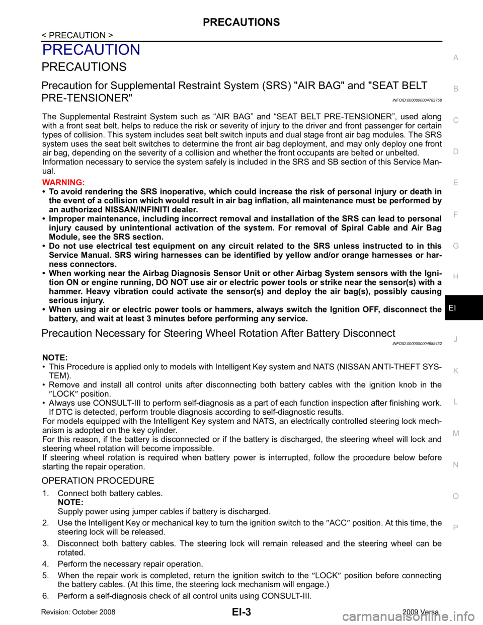
PRECAUTIONS
Precaution for Supplemental Restraint System (SRS) "AIR BAG" and "SEAT BELT
PRE-TENSIONER" INFOID:0000000004783758
The Supplemental Restraint System such as “A IR BAG” and “SEAT BELT PRE-TENSIONER”, used along
with a front seat belt, helps to reduce the risk or severi ty of injury to the driver and front passenger for certain
types of collision. This system includes seat belt switch inputs and dual stage front air bag modules. The SRS
system uses the seat belt switches to determine the front air bag deployment, and may only deploy one front
air bag, depending on the severity of a collision and w hether the front occupants are belted or unbelted.
Information necessary to service the system safely is included in the SRS and SB section of this Service Man-
ual.
WARNING:
• To avoid rendering the SRS inoper ative, which could increase the risk of personal injury or death in
the event of a collision which would result in air bag inflation, all maintenance must be performed by
an authorized NISSAN/INFINITI dealer.
• Improper maintenance, including in correct removal and installation of the SRS can lead to personal
injury caused by unintentional act ivation of the system. For removal of Spiral Cable and Air Bag
Module, see the SRS section.
• Do not use electrical test equipm ent on any circuit related to the SRS unless instructed to in this
Service Manual. SRS wiring harnesses can be identi fied by yellow and/or orange harnesses or har-
ness connectors.
• When working near the Airbag Diagnosis Sensor Un it or other Airbag System sensors with the Igni-
tion ON or engine running, DO NOT use air or el ectric power tools or strike near the sensor(s) with a
hammer. Heavy vibration could activate the sensor( s) and deploy the air bag(s), possibly causing
serious injury.
• When using air or electric power tools or hammers , always switch the Ignition OFF, disconnect the
battery, and wait at least 3 minutes before performing any service.
Precaution Necessary for Steering Wh eel Rotation After Battery Disconnect
INFOID:0000000004685432
NOTE:
• This Procedure is applied only to models with Inte lligent Key system and NATS (NISSAN ANTI-THEFT SYS-
TEM).
• Remove and install all control units after disconnecti ng both battery cables with the ignition knob in the
″ LOCK ″ position.
• Always use CONSULT-III to perform self-diagnosis as a part of each function inspection after finishing work.
If DTC is detected, perform trouble diagnosis according to self-diagnostic results.
For models equipped with the Intelligent Key system and NATS , an electrically controlled steering lock mech-
anism is adopted on the key cylinder.
For this reason, if the battery is disconnected or if the battery is discharged, the steering wheel will lock and
steering wheel rotation will become impossible.
If steering wheel rotation is required when battery pow er is interrupted, follow the procedure below before
starting the repair operation.
OPERATION PROCEDURE 1. Connect both battery cables. NOTE:
Supply power using jumper cables if battery is discharged.
2. Use the Intelligent Key or mechanical key to turn the ignition switch to the ″ACC ″ position. At this time, the
steering lock will be released.
3. Disconnect both battery cables. The steering lock will remain released and the steering wheel can be
rotated.
4. Perform the necessary repair operation.
5. When the repair work is completed, return the ignition switch to the ″LOCK ″ position before connecting
the battery cables. (At this time, the steering lock mechanism will engage.)
6. Perform a self-diagnosis check of al l control units using CONSULT-III.
Page 2952 of 4331
![NISSAN TIIDA 2009 Service Repair Manual PRECAUTIONS
EM-5
< PRECAUTION >
[HR16DE] C
D E
F
G H
I
J
K L
M A EM
NP
O
5. When the repair work is completed, return the ignition switch to the
″LOCK ″ position before connecting
t NISSAN TIIDA 2009 Service Repair Manual PRECAUTIONS
EM-5
< PRECAUTION >
[HR16DE] C
D E
F
G H
I
J
K L
M A EM
NP
O
5. When the repair work is completed, return the ignition switch to the
″LOCK ″ position before connecting
t](/manual-img/5/57398/w960_57398-2951.png)
PRECAUTIONS
EM-5
< PRECAUTION >
[HR16DE] C
D E
F
G H
I
J
K L
M A EM
NP
O
5. When the repair work is completed, return the ignition switch to the
″LOCK ″ position before connecting
the battery cables. (At this time, the steering lock mechanism will engage.)
6. Perform a self-diagnosis check of al l control units using CONSULT-III.
Precaution for Procedur e without Cowl Top Cover INFOID:0000000004784258
When performing the procedure after removing cowl top cover, cover
the lower end of windshield.
Precaution for Drain Coolant INFOID:0000000004784260
• Drain coolant when engine is cooled.
Precaution for Disco nnecting Fuel Piping INFOID:0000000004784261
• Before starting work, make sure no fire or spark producing items are in the work area.
• Release fuel pressure before disassembly.
• After disconnecting pipes, plug openings to stop fuel leakage.
Precaution for Removal and Disassembly INFOID:0000000004784262
• When instructed to use special service tools, use the spec ified tools. Always be careful to work safely, avoid
forceful or uninstructed operations.
• Exercise maximum care to avoid damage to mating or sliding surfaces.
• Cover openings of engine system with tape or the equiva lent, if necessary, to seal out foreign materials.
• Mark and arrange disassembly parts in an organized way for easy troubleshooting and assembly.
• When loosening nuts and bolts, as a basic rule, start with the one furthest outside, then the one diagonally opposite, and so on. If the order of loosening is specif ied, do exactly as specified. Power tools may be used
where noted in the step.
Precaution for Inspection, Repair and Replacement INFOID:0000000004784263
• Before repairing or replacing, thoroughly inspect parts. Inspect new replacement parts in the same way, and
replace if necessary.
Precaution for Assembly and Installation INFOID:0000000004784264
• Use torque wrench to tighten bolts or nuts to specification.
• When tightening nuts and bolts, as a basic rule, equally tighten in several different steps starting with the ones in center, then ones on inside and outside diagonally in this order. If the order of tightening is specified,
do exactly as specified.
• Replace with new gasket, packing, oil seal or O-ring.
• Thoroughly wash, clean, and air-blow each part. Carefully check oil or coolant passages for any restriction
and blockage.
• Avoid damaging sliding or mating surfaces. Completely remove foreign materials such as cloth lint or dust. Before assembly, oil sliding surfaces well.
• Release air within route after draining coolant.
• Before starting engine, apply fuel pressure to fuel lines with turning ignition switch ON (with engine stopped). Then make sure that there are no leaks at fuel line connections.
• After repairing, start engine and increase engine speed to check coolant, fuel, oil, and exhaust systems for leakage. PIIB3706J
Page 3004 of 4331

EM
NP
O
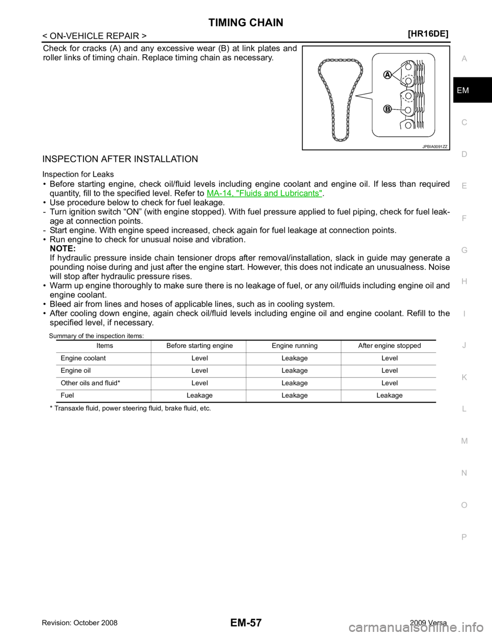
Check for cracks (A) and any excessive wear (B) at link plates and
roller links of timing chain. Replace timing chain as necessary.
INSPECTION AFTER INSTALLATION
Inspection for Leaks • Before starting engine, check oil/fluid levels incl uding engine coolant and engine oil. If less than required
quantity, fill to the specified level. Refer to MA-14, " Fluids and Lubricants " .
• Use procedure below to check for fuel leakage.
- Turn ignition switch “ON” (with engine stopped). With fuel pressure applied to fuel piping, check for fuel leak-
age at connection points.
- Start engine. With engine speed increased, check again for fuel leakage at connection points.
• Run engine to check for unusual noise and vibration. NOTE:
If hydraulic pressure inside chain tensioner drops after removal/installation, slack in guide may generate a
pounding noise during and just after the engine start. However, this does not indicate an unusualness. Noise
will stop after hydraulic pressure rises.
• Warm up engine thoroughly to make sure there is no leak age of fuel, or any oil/fluids including engine oil and
engine coolant.
• Bleed air from lines and hoses of applicable lines, such as in cooling system.
• After cooling down engine, again check oil/fluid levels including engine oil and engine coolant. Refill to the specified level, if necessary.
Summary of the inspection items:
* Transaxle fluid, power steering fluid, brake fluid, etc.
Page 3021 of 4331

Fluids and Lubricants " .
• Use procedure below to check for fuel leakage.
- Turn ignition switch “ON” (with engine stopped). With fuel pressure applied to fuel piping, check for fuel leak-
age at connection points.
- Start engine. With engine speed increased, che ck again for fuel leakage at connection points.
• Run engine to check for unusual noise and vibration. NOTE:
If hydraulic pressure inside timing chain tensioner drops after removal/installation, slack in the guide may
generate a pounding noise during and just after engine start. However, this is normal. Noise will stop after
hydraulic pressure rises.
• Warm up engine thoroughly to make sure there is no leakage of fuel, or any oil/fluids including engine oil and
engine coolant.
• Bleed air from lines and hoses of applicable lines, such as in cooling system.
• After cooling down engine, again check oil/fluid levels including engine oil and engine coolant. Refill to the
specified level, if necessary.
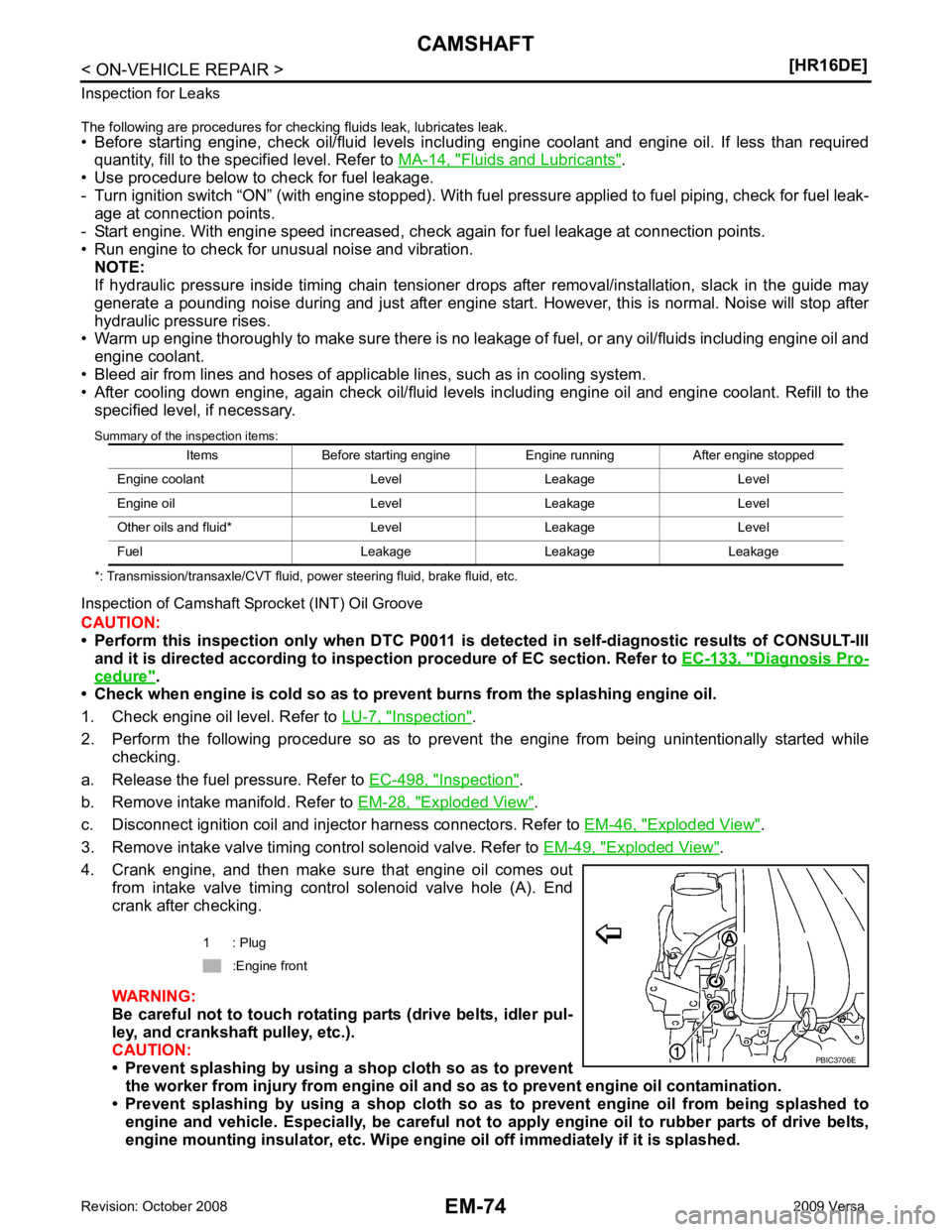
Summary of the inspection items:
*: Transmission/transaxle/CVT fluid, power steering fluid, brake fluid, etc.
Inspection of Camshaft Sprocket (INT) Oil Groove
CAUTION:
• Perform this inspection only when DTC P0011 is de tected in self-diagnostic results of CONSULT-III
and it is directed according to inspect ion procedure of EC section. Refer to EC-133, " Diagnosis Pro-
cedure " .
• Check when engine is cold so as to pr event burns from the splashing engine oil.
1. Check engine oil level. Refer to LU-7, " Inspection " .
2. Perform the following procedure so as to prevent the engine from being unintentionally started while
checking.
a. Release the fuel pressure. Refer to EC-498, " Inspection " .
b. Remove intake manifold. Refer to EM-28, " Exploded View " .
c. Disconnect ignition coil and injector harness connectors. Refer to EM-46, " Exploded View " .
3. Remove intake valve timing control solenoid valve. Refer to EM-49, " Exploded View " .
4. Crank engine, and then make sure that engine oil comes out from intake valve timing control solenoid valve hole (A). End
crank after checking.
WARNING:
Be careful not to touch rotating parts (drive belts, idler pul-
ley, and crankshaft pulley, etc.).
CAUTION:
• Prevent splashing by using a shop cloth so as to prevent
the worker from injury from engine oil an d so as to prevent engine oil contamination.
• Prevent splashing by using a shop cloth so as to prevent engine oil from being splashed to
engine and vehicle. Especially, be careful not to apply engine oil to rubber parts of drive belts,
engine mounting insulator, etc. Wipe engi ne oil off immediately if it is splashed.
Items Before starting engine Engine running After engine stopped
Engine coolant Level Leakage Level
Engine oil Level Leakage Level
Other oils and fluid* Level Leakage Level
Fuel Leakage Leakage Leakage 1 : Plug
:Engine front
Page 3074 of 4331
![NISSAN TIIDA 2009 Service Repair Manual PRECAUTIONS
EM-127
< SERVICE INFORMATION >
[MR18DE] C
D E
F
G H
I
J
K L
M A EM
NP
O
5. When the repair work is completed, return the ignition switch to the
″LOCK ″ position before c NISSAN TIIDA 2009 Service Repair Manual PRECAUTIONS
EM-127
< SERVICE INFORMATION >
[MR18DE] C
D E
F
G H
I
J
K L
M A EM
NP
O
5. When the repair work is completed, return the ignition switch to the
″LOCK ″ position before c](/manual-img/5/57398/w960_57398-3073.png)
PRECAUTIONS
EM-127
< SERVICE INFORMATION >
[MR18DE] C
D E
F
G H
I
J
K L
M A EM
NP
O
5. When the repair work is completed, return the ignition switch to the
″LOCK ″ position before connecting
the battery cables. (At this time, the steering lock mechanism will engage.)
6. Perform a self-diagnosis check of al l control units using CONSULT-III.
Precaution for Procedur e without Cowl Top Cover INFOID:0000000004307110
When performing the procedure after removing cowl top cover, cover
the lower end of windshield.
Precaution for Drain Coolant INFOID:0000000004307112
• Drain coolant when engine is cooled.
Precaution for Disco nnecting Fuel Piping INFOID:0000000004307113
• Before starting work, make sure no fire or spark producing items are in the work area.
• Release fuel pressure before disassembly.
• After disconnecting pipes, plug openings to stop fuel leakage.
Precaution for Removal and Disassembly INFOID:0000000004307114
• When instructed to use special service tools, use the spec ified tools. Always be careful to work safely, avoid
forceful or uninstructed operations.
• Exercise maximum care to avoid damage to mating or sliding surfaces.
• Cover openings of engine system with tape or the equiva lent, if necessary, to seal out foreign materials.
• Mark and arrange disassembly parts in an organized way for easy troubleshooting and assembly.
• When loosening nuts and bolts, as a basic rule, start with the one furthest outside, then the one diagonally opposite, and so on. If the order of loosening is specif ied, do exactly as specified. Power tools may be used
where noted in the step.
Precaution for Inspection, Repair and Replacement INFOID:0000000004307115
• Before repairing or replacing, thoroughly inspect parts. Inspect new replacement parts in the same way, and
replace if necessary.
Precaution for Assembly and Installation INFOID:0000000004307116
• Use torque wrench to tighten bolts or nuts to specification.
• When tightening nuts and bolts, as a basic rule, equally tighten in several different steps starting with the ones in center, then ones on inside and outside diagonally in this order. If the order of tightening is specified,
do exactly as specified.
• Replace with new gasket, packing, oil seal or O-ring.
• Thoroughly wash, clean, and air-blow each part. Carefully check oil or coolant passages for any restriction
and blockage.
• Avoid damaging sliding or mating surfaces. Completely remove foreign materials such as cloth lint or dust. Before assembly, oil sliding surfaces well.
• Release air within route after draining coolant.
• Before starting engine, apply fuel pressure to fuel lines with turning ignition switch ON (with engine stopped). Then make sure that there are no leaks at fuel line connections.
• After repairing, start engine and increase engine speed to check coolant, fuel, oil, and exhaust systems for leakage. PIIB3706J