Page 336 of 4331
AT
N
O P
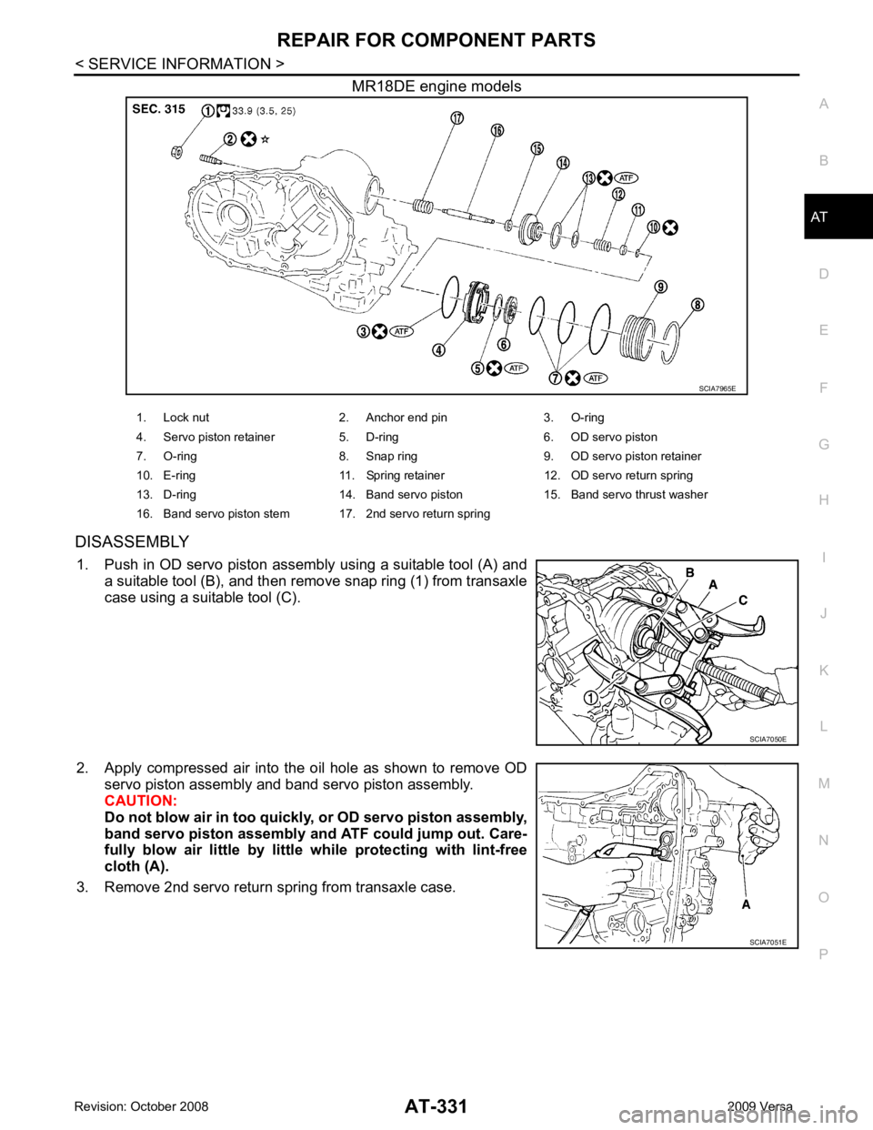
MR18DE engine models
DISASSEMBLY 1. Push in OD servo piston assembly using a suitable tool (A) and a suitable tool (B), and then remove snap ring (1) from transaxle
case using a suitable tool (C).
2. Apply compressed air into the oil hole as shown to remove OD servo piston assembly and band servo piston assembly.
CAUTION:
Do not blow air in too quickl y, or OD servo piston assembly,
band servo piston assembly and ATF could jump out. Care-
fully blow air little by littl e while protecting with lint-free
cloth (A).
3. Remove 2nd servo return spring from transaxle case. SCIA7051E
Page 348 of 4331
AT
N
O P
ASSEMBLY
Assembly (1) INFOID:0000000004305528
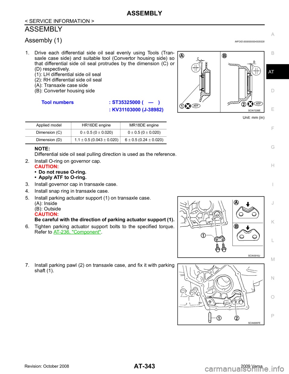
1. Drive each differential side oil seal evenly using Tools (Tran- saxle case side) and suitable tool (Convertor housing side) so
that differential side oil seal protrudes by the dimension (C) or
(D) respectively.
(1): LH differential side oil seal
(2): RH differential side oil seal
(A): Transaxle case side
(B): Converter housing side
Unit: mm (in)
NOTE:
Differential side oil seal pulling direction is used as the reference.
2. Install O-ring on governor cap. CAUTION:
• Do not reuse O-ring.
• Apply ATF to O-ring.
3. Install governor cap in transaxle case.
4. Install snap ring in transaxle case.
5. Install parking actuator support (1) on transaxle case. (A): Inside
(B): Outside
CAUTION:
Be careful with the direction of parking actuator support (1).
6. Tighten parking actuator support bolts to the specified torque. Refer to AT-236, " Component " .
7. Install parking pawl (2) on transaxle case, and fix it with parking shaft (1).Tool numbers : ST35325000 ( — )
: KV31103000 (J-38982)
Applied model HR16DE engine MR18DE engine
Dimension (C) 0 ± 0.5 (0 ± 0.020) 0 ± 0.5 (0 ± 0.020)
Dimension (D) 1.1 ± 0.5 (0.043 ± 0.020) 6 ± 0.5 (0.24 ± 0.020)
Page 353 of 4331
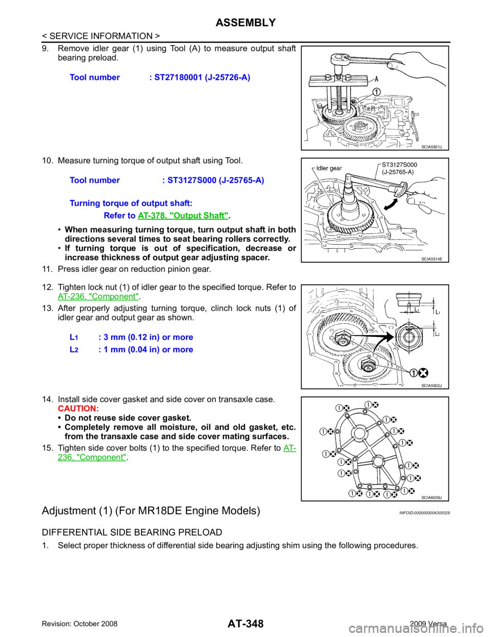
Component " .
13. After properly adjusting turning torque, clinch lock nuts (1) of idler gear and output gear as shown.
14. Install side cover gasket and side cover on transaxle case. CAUTION:
• Do not reuse side cover gasket.
• Completely remove all moisture, oil and old gasket, etc. from the transaxle case and side cover mating surfaces.
15. Tighten side cover bolts (1) to the specified torque. Refer to AT-236, " Component " .
Adjustment (1) (For MR18DE Engine Models) INFOID:0000000004305529
DIFFERENTIAL SIDE BEARING PRELOAD
1. Select proper thickness of differential side bearing adjusting shim using the following procedures. Tool number : ST27180001 (J-25726-A)
Output Shaft " .
SCIA6039J
Page 369 of 4331
" Component " .
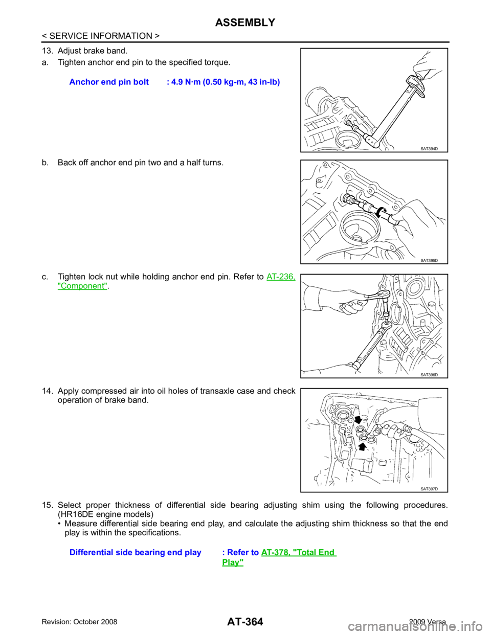
14. Apply compressed air into oil holes of transaxle case and check operation of brake band.
15. Select proper thickness of differential side bear ing adjusting shim using the following procedures.
(HR16DE engine models)
• Measure differential side bearing end play, and calculat e the adjusting shim thickness so that the end
play is within the specifications. Anchor end pin bolt : 4.9
N·m (0.50 kg-m, 43 in-lb) SAT395D
SAT396D
Total End
Play "
Page 371 of 4331
AT-366< SERVICE INFORMATION >
ASSEMBLY
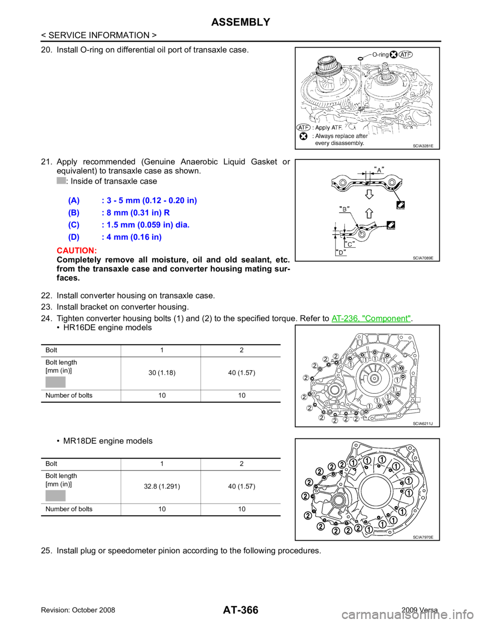
20. Install O-ring on differential oil port of transaxle case.
21. Apply recommended (Genuine Anaerobic Liquid Gasket or equivalent) to transaxle case as shown.
: Inside of transaxle case
CAUTION:
Completely remove all moisture, oil and old sealant, etc.
from the transaxle case and converter housing mating sur-
faces.
22. Install converter housing on transaxle case.
23. Install bracket on converter housing.
24. Tighten converter housing bolts (1) and (2) to the specified torque. Refer to AT-236, " Component " .
• HR16DE engine models
• MR18DE engine models
25. Install plug or speedometer pinion according to the following procedures. SCIA3281E
(A) : 3 - 5 mm (0.12 - 0.20 in)
(B) : 8 mm (0.31 in) R
(C) : 1.5 mm (0.059 in) dia.
(D) : 4 mm (0.16 in) SCIA7089E
Bolt 1 2
Bolt length
[mm (in)] 30 (1.18) 40 (1.57)
Number of bolts 10 10 SCIA6211J
Bolt 1 2
Bolt length
[mm (in)] 32.8 (1.291) 40 (1.57)
Number of bolts 10 10 SCIA7970E
Page 374 of 4331
AT
N
O P
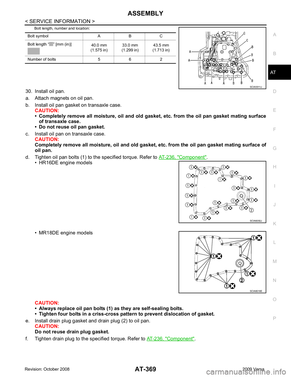
Bolt length, number and location:
30. Install oil pan.
a. Attach magnets on oil pan.
b. Install oil pan gasket on transaxle case. CAUTION:
• Completely remove all moisture, oil and old gasket , etc. from the oil pan gasket mating surface
of transaxle case.
• Do not reuse oil pan gasket.
c. Install oil pan on transaxle case. CAUTION:
Completely remove all moisture, oil and old gasket , etc. from the oil pan gasket mating surface of
oil pan.
d. Tighten oil pan bolts (1) to the specified torque. Refer to AT-236, " Component " .
• HR16DE engine models
• MR18DE engine models
CAUTION:
• Always replace oil pan bolts (1) as they are self-sealing bolts.
• Tighten four bolts in a criss-cross pattern to prevent dislocation of gasket.
e. Install drain plug gasket and drain plug (2) to oil pan. CAUTION:
Do not reuse drain plug gasket.
f. Tighten drain plug to the specified torque. Refer to AT-236, " Component " .
Bolt symbol A B C
Bolt length “ ” [mm (in)] 40.0 mm
(1.575 in) 33.0 mm
(1.299 in) 43.5 mm
(1.713 in)
Number of bolts 5 6 2 SCIA6050J
Page 382 of 4331
AT
N
O P
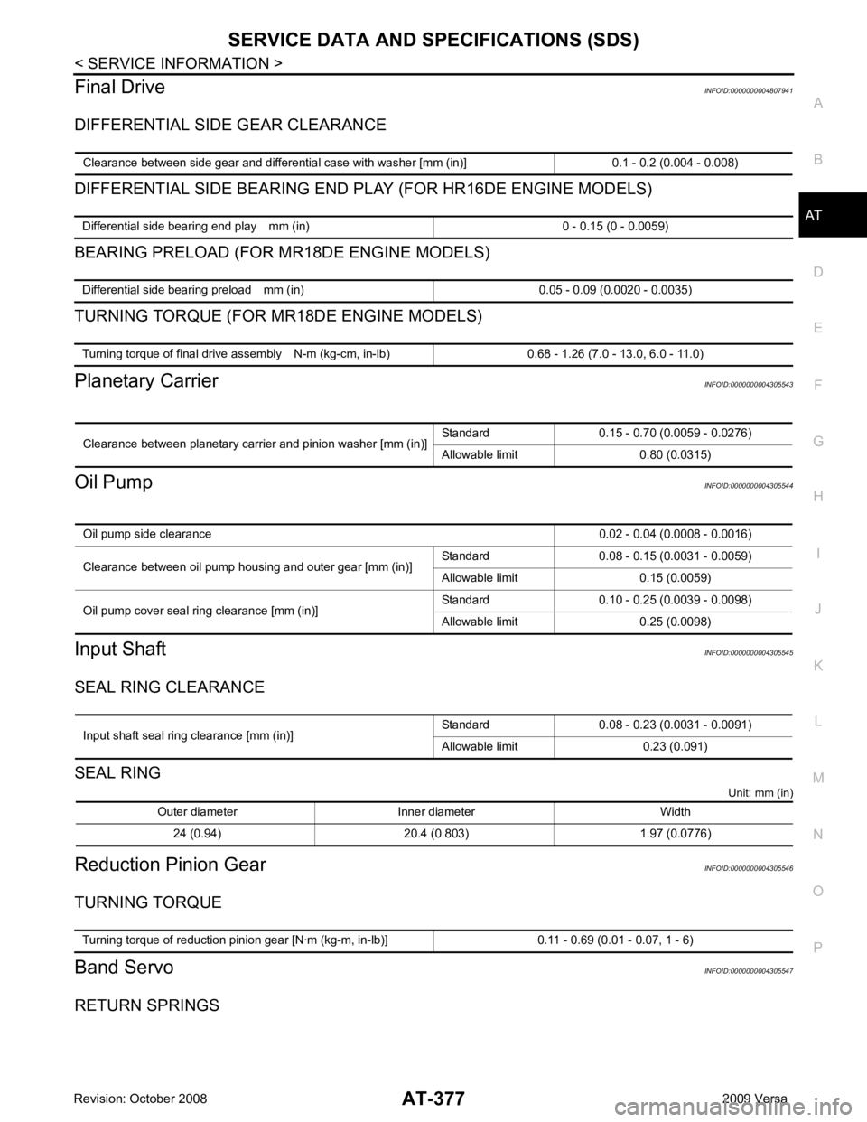
Final Drive
INFOID:0000000004807941
DIFFERENTIAL SIDE GEAR CLEARANCE
DIFFERENTIAL SIDE BEARING END PL AY (FOR HR16DE ENGINE MODELS)
BEARING PRELOAD (FOR MR18DE ENGINE MODELS)
TURNING TORQUE (FOR MR18DE ENGINE MODELS)
Planetary Carrier INFOID:0000000004305543
Oil Pump INFOID:0000000004305544
Input Shaft INFOID:0000000004305545
SEAL RING CLEARANCE
SEAL RING Unit: mm (in)
Reduction Pinion Gear INFOID:0000000004305546
TURNING TORQUE
Band Servo INFOID:0000000004305547
RETURN SPRINGS Clearance between side gear and differential case with washer [mm (in)] 0.1 - 0.2 (0.004 - 0.008) Differential side bearing end play mm (in) 0 - 0.15 (0 - 0.0059)
Differential side bearing preload mm (in) 0.05 - 0.09 (0.0020 - 0.0035)
Turning torque of final drive assembly N-m (kg-cm, in-lb) 0.68 - 1.26 (7.0 - 13.0, 6.0 - 11.0)
Clearance between planetary carrier and pinion washer [mm (in)]
Standard 0.15 - 0.70 (0.0059 - 0.0276)
Allowable limit 0.80 (0.0315) Oil pump side clearance
0.02 - 0.04 (0.0008 - 0.0016)
Clearance between oil pump housing and outer gear [mm (in)] Standard 0.08 - 0.15 (0.0031 - 0.0059)
Allowable limit 0.15 (0.0059)
Oil pump cover seal ring clearance [mm (in)] Standard 0.10 - 0.25 (0.0039 - 0.0098)
Allowable limit 0.25 (0.0098) Input shaft seal ring clearance [mm (in)]
Standard 0.08 - 0.23 (0.0031 - 0.0091)
Allowable limit 0.23 (0.091) Outer diameter Inner diameter Width
24 (0.94) 20.4 (0.803) 1.97 (0.0776) Turning torque of reduction pinion gear [N·m (kg-m, in-lb)] 0.11 - 0.69 (0.01 - 0.07, 1 - 6)
Page 823 of 4331
BR
N
O P
VACUUM LINES
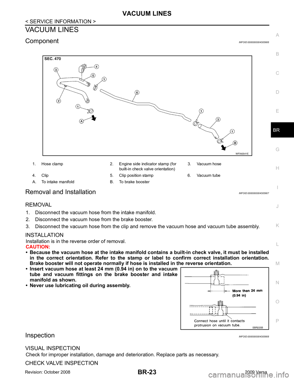
Component INFOID:0000000004305906
Removal and Installation INFOID:0000000004305907
REMOVAL 1. Disconnect the vacuum hose from the intake manifold.
2. Disconnect the vacuum hose from the brake booster.
3. Disconnect the vacuum hose from the clip and re move the vacuum hose and vacuum tube assembly.
INSTALLATION Installation is in the reverse order of removal.
CAUTION:
• Because the vacuum hose at the intake manifold contai ns a built-in check valve, it must be installed
in the correct orientation. Refer to the stamp or label to confirm correct installation orientation.
Brake booster will not operate normally if ho se is installed in the reverse orientation.
• Insert vacuum hose at least 24 mm (0.94 in) on to the vacuum tube and vacuum fittings on the brake booster and intake
manifold as shown.
• Never use lubricating oil during assembly.
Inspection INFOID:0000000004305908
VISUAL INSPECTION Check for improper installation, damage and deterioration. Replace parts as necessary.
CHECK VALVE INSPECTION 1. Hose clamp 2. Engine side indicator stamp (for
built-in check valve orientation)3. Vacuum hose
4. Clip 5. Clip position stamp 6. Vacuum tube
A. To intake manifold B. To brake booster SBR225B