2009 NISSAN TIIDA engine oil
[x] Cancel search: engine oilPage 79 of 4331

ON vehicle
1. Ignition switch and starter
PG-3 ,
SC-9 2. Control cable adjustment
AT-216 3. PNP switch adjustment
AT-224Engine starts in posi-
tions other than “P”
and “N”. ON vehicle
1. Control cable adjustment
AT-216 2. PNP switch adjustment
AT-224Transaxle noise in“ P”
and “N” positions. ON vehicle1. A/T fluid level
AT-17 2. Line pressure test
AT-51 3. Accelerator pedal position sensor
EC-412
(HR16DE), EC- 959 (MR Type 1)
or EC-1481 (MR
Type 2)
4. Vehicle speed sensor·A/T (Revolution sensor)
and vehicle speed sensor·MTR AT-101 ,
AT-154 OFF vehicle
5. Oil pump
AT-277 6. Torque converter
AT-256Items Symptom Condition Diagnostic item Reference page
Page 81 of 4331

2. PNP switch adjustment
AT-224 3. Overdrive control switch
AT-172 4. Accelerator pedal position sensor
EC-412
(HR16DE), EC- 959 (MR Type 1)
or EC-1481 (MR
Type 2)
5. Vehicle speed sensor·A/T (Revolution sensor)
and vehicle speed sensor·MTR AT-101 ,
AT-154 6. Shift solenoid valve A
AT-139 7. Shift solenoid valve B
AT-144 8. Control valve assembly
AT-221 OFF vehicle
9. Reverse clutch
AT-296 10. High clutch
AT-301 11. Brake band
AT-330 12. Low & reverse brake
AT-313 13. Oil pump
AT-277 14. Torque converter
AT-256Transaxle noise in
“D”, “2”, “1” and “R”
positions. ON vehicle 1. A/T fluid level
AT-17OFF vehicle 2. Torque converter
AT-256Engine brake does
not operate in “1” po-
sition. ON vehicle1. PNP switch adjustment
AT-224 2. Control cable adjustment
AT-216 3. Vehicle speed sensor·A/T (Revolution sensor)
and vehicle speed sensor·MTR AT-101 ,
AT-154 4. Control valve assembly
AT-221 5. Overrun clutch solenoid valve
AT-149 OFF vehicle
6. Overrun clutch
AT-306 7. Low & reverse brake
AT-313Transaxle overheats.
ON vehicle1. A/T fluid level
AT-17 2. Engine idling speed
EC-30
(HR16DE), EC- 570 (MR Type 1)
or EC-1082 (MR
Type 2)
3. Accelerator pedal position sensor EC-412
(HR16DE), EC- 959 (MR Type 1)
or EC-1481 (MR
Type 2)
4. Line pressure test AT-51 5. Line pressure solenoid valve
AT-134 6. Control valve assembly
AT-221 OFF vehicle
7. Oil pump
AT-277 8. Reverse clutch
AT-296 9. High clutch
AT-301 10. Brake band
AT-330 11. Forward clutch
AT-306 12. Overrun clutch
AT-306Items Symptom Condition Diagnostic item Reference page
Page 124 of 4331

AT
N
O P
DTC P0734 A/T 4TH GEAR FUNCTION
Description INFOID:0000000004305383
• This malfunction will not be detected while the OD OFF indicator lamp is indicating another self-diagnosis malfunction.
• This malfunction is detected when the A/T does not shif t into fourth gear position or the torque converter
clutch does not lock up as instructed by the TCM. This is not caused by electrical malfunction (circuits open
or shorted) but by mechanical malfunction such as c ontrol valve sticking, improper solenoid valve operation,
malfunctioning oil pump or torque converter clutch, etc.
CONSULT-III Reference Val ue in Data Monitor Mode INFOID:0000000004305384
Remarks: Specification data are reference values.
On Board Diagnosis Logic INFOID:0000000004305385
• This is an OBD-II self-diagnostic item.
• Diagnostic trouble code “P0734 A/T 4TH GR FNCTN” with CONSULT-III is detected when A/T cannot be
shifted to the 4th gear position even if electrical circuit is good.
• This diagnosis monitors actual gear position by checki ng the torque converter slip ratio calculated by TCM
as follows:
Torque converter slip ratio = A x C/B
A: Output shaft revolution signal from revolution sensor
B: Engine speed signal from ECM
C: Gear ratio determined as gear position which TCM supposes
If the actual gear position is much lower than the pos ition (4th) supposed by TCM, the slip ratio will be much
less than normal. In case the ratio does not reach t he specified value, TCM judges this diagnosis malfunc-
tion.
This malfunction will be caused when shift solenoid valve A is stuck open or shift solenoid valve B is stuck
closed.
• Gear positions supposed by TCM are as follows.
In case of gear position with no malfunctions: 1, 2, 3 and 4 positions
In case of gear position with shift solenoid valve A stuck open: 2, 2, 3 and 3* positions
In case of gear position with shift solenoid valve B stuck closed: 1, 2, 2 and 1* positions to each gear position
above
*: “P0734 A/T 4TH GR FNCTN” is detected.
Possible Cause INFOID:0000000004305386
• Shift solenoid valve A
• Shift solenoid valve B
• Line pressure solenoid valve
• Each clutch
• Hydraulic control circuit
DTC Confirmation Procedure INFOID:0000000004305387
CAUTION:
• Always drive vehicle at a safe speed.
• If performing this “DTC Confirmation Procedure” again, always turn ignition switch OFF and wait at
least 10 seconds before continuing.
After the repair, perform the following procedure to confirm the malfunction is eliminated. Gear position 1 2 3 4
Shift solenoid valve A ON (Closed) OFF (Open) OFF (Open) ON (Closed)
Shift solenoid valve B ON (Closed) ON (Closed) OFF (Open) OFF (Open) Item name Condition Display value (Approx.)
LINE PRES DTY Small throttle opening (Low line pressure)
⇔ Large
throttle opening (High line pressure) 0%
⇔ 94%
Page 134 of 4331

AT
N
O P
DTC P0744 A/T TCC S/V FUNCTION (LOCK-UP)
Description INFOID:0000000004305397
• This malfunction will not be detected while the OD OFF indicator lamp is indicating another self-diagnosis malfunction.
• This malfunction is detected when the A/T does not shif t into fourth gear position or the torque converter
clutch does not lock-up as instructed by the TCM. This is not caused by electrical malfunction (circuits open
or shorted) but by mechanical malfunction such as c ontrol valve sticking, improper solenoid valve operation,
malfunctioning oil pump or torque converter clutch, etc.
CONSULT-III Reference Val ue in Data Monitor Mode INFOID:0000000004305398
Remarks: Specification data are reference values.
On Board Diagnosis Logic INFOID:0000000004305399
• This is an OBD-II self-diagnostic item.
• Diagnostic trouble code “P0744 A/T TCC S/V FNCTN” wi th CONSULT-III is detected when A/T cannot per-
form lock-up even if electrical circuit is good.
• This diagnosis monitors actual gear position by checki ng the torque converter slip ratio calculated by TCM
as follows:
Torque converter slip ratio = A x C/B
A: Output shaft revolution signal from revolution sensor
B: Engine speed signal from ECM
C: Gear ratio determined as gear position which TCM supposes
If the actual gear position is much lower than the pos ition (4th) supposed by TCM, the slip ratio will be much
less than normal. In case the ratio does not reach t he specified value, TCM judges this diagnosis malfunc-
tion.
This malfunction will be caused when shift solenoid valve B is stuck closed.
• Gear positions supposed by TCM are as follows.
In case of gear position with no malfunctions: 1, 2, 3 and 4 positions
In case of gear position with shift solenoid valve B stu ck closed: 1, 2, 2 and 1* positions to each gear position
above
*: “P0744 A/T TCC S/V FNCTN” is detected.
Possible Cause INFOID:0000000004305400
• Line pressure solenoid valve
• Torque converter clutch solenoid valve
• Each clutch
• Hydraulic control circuit
DTC Confirmation Procedure INFOID:0000000004305401
CAUTION:
• Always drive vehicle at a safe speed.
• If performing this “DTC Confirmation Procedure” again, always turn ignition switch OFF and wait at
least 10 seconds before continuing.
After the repair, perform the following procedure to confirm the malfunction is eliminated.
WITH CONSULT-III
1. Start engine and select “DATA MONITOR” m ode for “TRANSMISSION” with CONSULT-III.
2. Touch “START”.
3. Make sure that output voltage of A/T fluid temperature sensor is within the range below. FLUID TEMP SE: 0.4 - 1.5 V
If out of range, drive vehicle to decrease voltage (warm up the fluid) or stop engine to increase voltage
(cool down the fluid).
4. Select “TCC S/V FNCTN P0744” of “DTC & SR T CONFIRMATION” mode for “TRANSMISSION” with
CONSULT-III and touch “START”.
Item name Condition Display value (Approx)
TCC S/V DUTY Lock-up OFF ⇔ Lock-up ON 4% ⇔ 94%
Page 166 of 4331
DTC BATT/FLUID TEMP SEN (A/T FLU
ID TEMP SENSOR CIRCUIT AND TCM
POWER SOURCE)
AT-161
< SERVICE INFORMATION >
D
E
F
G H
I
J
K L
M A
B AT
N
O P
OK >> GO TO 7.
NG >> Repair open circuit or short to ground or short to power in harness or connectors. 7.
CHECK A/T FLUID TEMPERATURE SENSOR WITH TERMINAL CORD ASSEMBLY
1. Turn ignition switch OFF.
2. Disconnect terminal cord assembly connector in engine room.
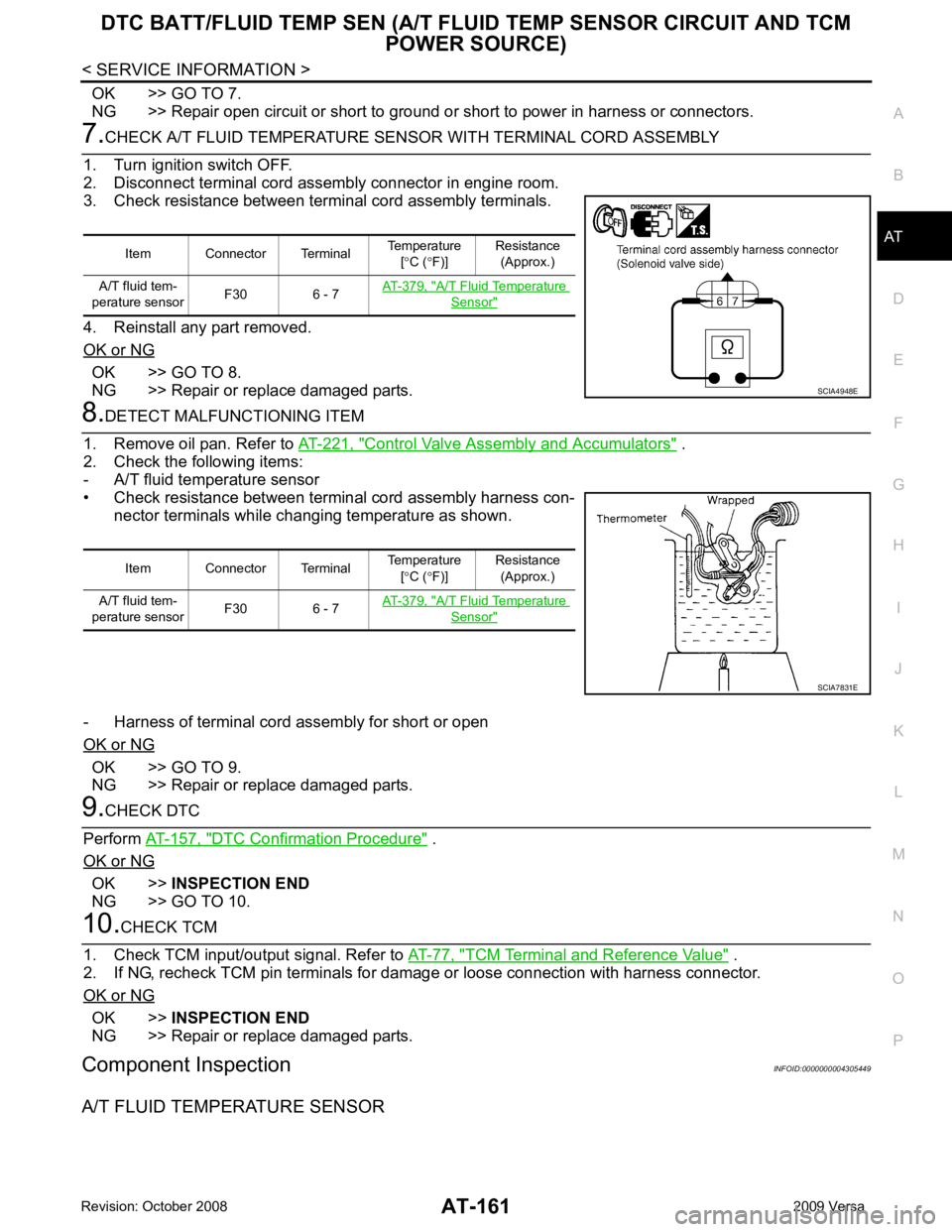
3. Check resistance between terminal cord assembly terminals.
4. Reinstall any part removed.
OK or NG OK >> GO TO 8.
NG >> Repair or replace damaged parts. 8.
DETECT MALFUNCTIONING ITEM
1. Remove oil pan. Refer to AT-221, " Control Valve Assembly and Accumulators " .
2. Check the following items:
- A/T fluid temperature sensor
• Check resistance between terminal cord assembly harness con- nector terminals while changing temperature as shown.
- Harness of terminal cord assembly for short or open
OK or NG OK >> GO TO 9.
NG >> Repair or replace damaged parts. 9.
CHECK DTC
Perform AT-157, " DTC Confirmation Procedure " .
OK or NG OK >>
INSPECTION END
NG >> GO TO 10. 10.
CHECK TCM
1. Check TCM input/output signal. Refer to AT-77, " TCM Terminal and Reference Value " .
2. If NG, recheck TCM pin terminals for dam age or loose connection with harness connector.
OK or NG OK >>
INSPECTION END
NG >> Repair or replace damaged parts.
Component Inspection INFOID:0000000004305449
A/T FLUID TEMPERATURE SENSOR Item Connector Terminal
Temperature
[° C ( °F)] Resistance
(Approx.)
A/T fluid tem-
perature sensor F30 6 - 7 AT-379, " A/T Fluid Temperature
Sensor "
SCIA4948E
Item Connector Terminal
Temperature
[° C ( °F)] Resistance
(Approx.)
A/T fluid tem-
perature sensor F30 6 - 7 AT-379, " A/T Fluid Temperature
Sensor "
SCIA7831E
Page 206 of 4331
TROUBLE DIAGNOSIS FOR SYMPTOMS
AT-201
< SERVICE INFORMATION >
D
E
F
G H
I
J
K L
M A
B AT
N
O P
OK >> GO TO 3
NG >> Check PNP switch. Refer to AT-176, " Component Inspection " .
2.
CHECK PNP SWITCH CIRCUIT
Without CONSULT-III
1. Turn ignition switch ON. (Do not start engine.)
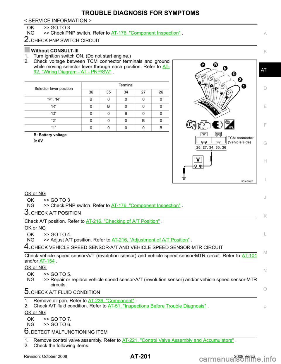
2. Check voltage between TCM connector terminals and ground
while moving selector lever through each position. Refer to AT-92, " Wiring Diagram - AT - PNP/SW " .
B: Battery voltage
0: 0V
OK or NG OK >> GO TO 3
NG >> Check PNP switch. Refer to AT-176, " Component Inspection " .
3.
CHECK A/T POSITION
Check A/T position. Refer to AT-216, " Checking of A/T Position " .
OK or NG OK >> GO TO 4.
NG >> Adjust A/T position. Refer to AT-216, " Adjustment of A/T Position " .
4.
CHECK VEHICLE SPEED SENS OR·A/T AND VEHICLE SPEED SENSOR·MTR CIRCUIT
Check vehicle speed sensor·A/T (re volution sensor) and vehicle speed sensor·MTR circuit. Refer to AT-101and/or
AT-154 .
OK or NG OK >> GO TO 5.
NG >> Repair or replace vehicle speed sensor·A/T (revolution sensor) and/or vehicle speed sensor·MTR
circuits. 5.
CHECK A/T FLUID CONDITION
1. Remove oil pan. Refer to AT-236, " Component " .
2. Check A/T fluid condition. Refer to AT-51, " Inspections Before Trouble Diagnosis " .
OK or NG OK >> GO TO 7.
NG >> GO TO 6. 6.
DETECT MALFUNCTIONING ITEM
1. Remove control valve assembly. Refer to AT-221, " Control Valve Assembly and Accumulators " .
2. Check the following items: Selector lever position
Terminal
36 35 34 27 26
“P”, “N” B 0 0 0 0 “R” 0 B 0 0 0
“D” 0 0 B 0 0 “2” 0 0 0 B 0
“1” 0 0 0 0 B SCIA7162E
Page 226 of 4331
AT
N
O P
ON-VEHICLE SERVICE
Control Valve Assembly and Accumulators INFOID:0000000004305503
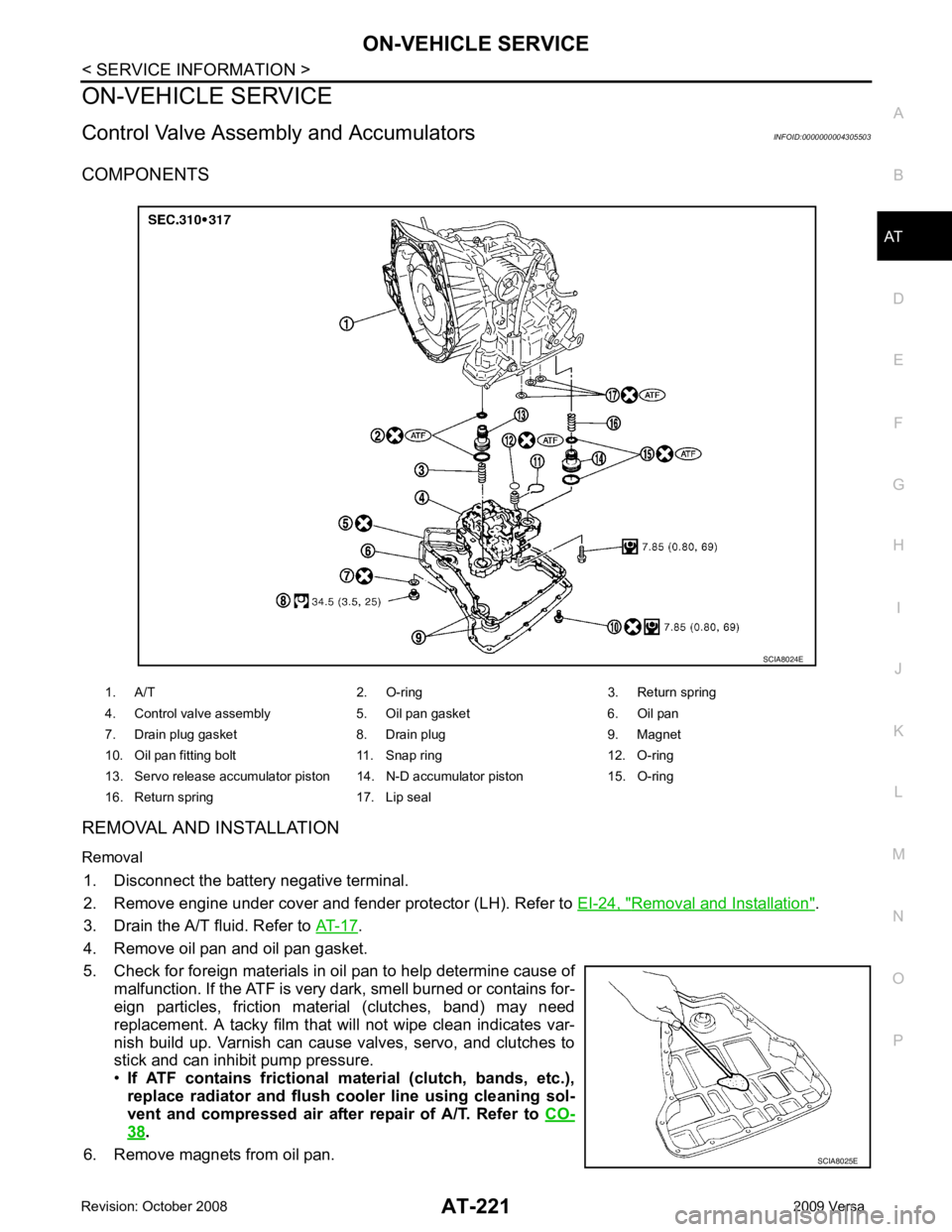
COMPONENTS
REMOVAL AND INSTALLATION
Removal 1. Disconnect the battery negative terminal.
2. Remove engine under cover and fender protector (LH). Refer to EI-24, " Removal and Installation " .
3. Drain the A/T fluid. Refer to AT-17 .
4. Remove oil pan and oil pan gasket.
5. Check for foreign materials in oil pan to help determine cause of malfunction. If the ATF is very dark, smell burned or contains for-
eign particles, friction material (clutches, band) may need
replacement. A tacky film that will not wipe clean indicates var-
nish build up. Varnish can cause valves, servo, and clutches to
stick and can inhibit pump pressure.
• If ATF contains frictional material (clutch, bands, etc.),
replace radiator and flush cooler line using cleaning sol-
vent and compressed air after repair of A/T. Refer to CO-38 .
6. Remove magnets from oil pan. 1. A/T 2. O-ring 3. Return spring
4. Control valve assembly 5. Oil pan gasket 6. Oil pan
7. Drain plug gasket 8. Drain plug 9. Magnet
10. Oil pan fitting bolt 11. Snap ring 12. O-ring
13. Servo release accumulator piston 14. N-D accumulator piston 15. O-ring
16. Return spring 17. Lip seal SCIA8025E
Page 254 of 4331

AT
N
O P
Oil Channel
INFOID:0000000004305511
HR16DE ENGINE MODELS 19. Oil pan 20. Drain plug gasket 21. Drain plug
22. Magnet 23. Oil pan bolt 24. Snap ring
25. O-ring 26. O-ring 27. N-D accumulator piston
28. Return spring 29. O-ring 30. Lip seal
31. Turbine revolution sensor (power train revolution sensor) 32. O-ring 33. Retaining pin
34. Detent spring 35. Retaining pin 36. Manual shaft
37. Manual shaft oil seal 38. Manual plate 39. Parking rod plate
40. Parking rod 41. OD servo piston retainer 42. Snap ring
43. O-ring 44. OD servo piston 45. D-ring
46. Servo piston retainer 47. O-ring 48. E-ring
49. Spring retainer 50. OD servo return spring 51. D-ring
52. Band servo piston 53. Band servo thrust washer 54. Band servo piston stem
55. 2nd servo return spring 56. PNP switch 57. Parking shaft
58. Return spring 59. Thrust needle bearing 60. Seal ring
61. Output shaft 62. Output shaft bearing 63. Output shaft adjusting shim
64. Side cover 65. Side cover bolt 66. Lock nut
67. Idler gear 68. Idler gear bearing 69. Reduction pinion gear adjusting shim
70. Parking actuator support 71. Parking pawl 72. LH differential side oil seal
73. Revolution sensor
: Apply Genuine Anaerobic Liquid Gasket or equivalent.