2009 NISSAN TIIDA engine oil
[x] Cancel search: engine oilPage 842 of 4331
![NISSAN TIIDA 2009 Service Repair Manual BRC-2< SERVICE INFORMATION >
[ABS]
PRECAUTIONS
SERVICE INFORMATION
PRECAUTIONS
Precaution for Supplemental Restraint Syst em (SRS) "AIR BAG" and "SEAT BELT
PRE-TENSIONER" INFOID:0000000004784402
The](/manual-img/5/57398/w960_57398-841.png "NISSAN TIIDA 2009 Service Repair Manual BRC-2< SERVICE INFORMATION >
[ABS]
PRECAUTIONS
SERVICE INFORMATION
PRECAUTIONS
Precaution for Supplemental Restraint Syst em (SRS) \"AIR BAG\" and \"SEAT BELT
PRE-TENSIONER\" INFOID:0000000004784402
The")
BRC-2< SERVICE INFORMATION >
[ABS]
PRECAUTIONS
SERVICE INFORMATION
PRECAUTIONS
Precaution for Supplemental Restraint Syst em (SRS) "AIR BAG" and "SEAT BELT
PRE-TENSIONER" INFOID:0000000004784402
The Supplemental Restraint System such as “A IR BAG” and “SEAT BELT PRE-TENSIONER”, used along
with a front seat belt, helps to reduce the risk or severi ty of injury to the driver and front passenger for certain
types of collision. This system includes seat belt switch inputs and dual stage front air bag modules. The SRS
system uses the seat belt switches to determine the front air bag deployment, and may only deploy one front
air bag, depending on the severity of a collision and w hether the front occupants are belted or unbelted.
Information necessary to service the system safely is included in the SRS and SB section of this Service Man-
ual.
WARNING:
• To avoid rendering the SRS inopera tive, which could increase the risk of personal injury or death in
the event of a collision which would result in air bag inflation, all maintenance must be performed by
an authorized NISS AN/INFINITI dealer.
• Improper maintenance, including incorrect removal and installation of the SRS can lead to personal
injury caused by unintent ional activation of the system. For re moval of Spiral Cable and Air Bag
Module, see the SRS section.
• Do not use electrical test equipmen t on any circuit related to the SRS unless instructed to in this
Service Manual. SRS wiring harn esses can be identified by yellow and/or orange harnesses or har-
ness connectors.
PRECAUTIONS WHEN USING POWER TOOLS (AIR OR ELECTRIC) AND HAMMERS
WARNING:
• When working near the Airbag Diagnosis Sensor Unit or other Airbag System sensors with the Igni-
tion ON or engine running, DO NOT use air or electri c power tools or strike near the sensor(s) with a
hammer. Heavy vibration could activate the sensor( s) and deploy the air bag(s), possibly causing
serious injury.
• When using air or electric power tools or hammers , always switch the Ignition OFF, disconnect the
battery, and wait at least 3 minu tes before performing any service.
Precaution for Brake System INFOID:0000000004307251
CAUTION:
• Refer to MA-14 for recommended brake fluid.
• Never reuse drained brake fluid.
• Be careful not to splash brake fluid on painted areas; it may cause paint damage. If brake fluid is
splashed on painted areas, wash it away with water immediately.
• To clean or wash all parts of master cylin der and disc brake caliper, use clean brake fluid.
• Never use mineral oils such as gasoline or kerosene. They will ruin rubber parts of the hydraulic sys-
tem.
• Use flare nut wrench when re moving and installing brake
tube.
• If a brake fluid leak is found, the part must be disassembled
without fail. Then it has to be replaced with a new one if a
defect exists.
• Turn the ignition switch OFF an d remove the connector of the
ABS actuator and electric unit (c ontrol unit) or the battery ter-
minal before performing the work.
• Always torque brake lines when installing.
• Burnish the brake contact surf aces after refinishing or replac-
ing rotors, after replacing pads, or if a soft pedal occurs at
very low mileage. Refer to BR-32, " Brake Burnishing Proce-
dure " .
WARNING:
• Clean brake pads and shoes with a waste cloth, then wipe with a dust collector. SBR686C
Page 878 of 4331
CL-2< SERVICE INFORMATION >
PRECAUTIONS
SERVICE INFORMATION
PRECAUTIONS
Precaution for Supplemental Restraint Syst em (SRS) "AIR BAG" and "SEAT BELT
PRE-TENSIONER" INFOID:0000000004802358
The Supplemental Restraint System such as “A IR BAG” and “SEAT BELT PRE-TENSIONER”, used along
with a front seat belt, helps to reduce the risk or severi ty of injury to the driver and front passenger for certain
types of collision. This system includes seat belt switch inputs and dual stage front air bag modules. The SRS
system uses the seat belt switches to determine the front air bag deployment, and may only deploy one front
air bag, depending on the severity of a collision and w hether the front occupants are belted or unbelted.
Information necessary to service the system safely is included in the SRS and SB section of this Service Man-
ual.
WARNING:
• To avoid rendering the SRS inopera tive, which could increase the risk of personal injury or death in
the event of a collision which would result in air bag inflation, all maintenance must be performed by
an authorized NISS AN/INFINITI dealer.
• Improper maintenance, including incorrect removal and installation of the SRS can lead to personal
injury caused by unintent ional activation of the system. For re moval of Spiral Cable and Air Bag
Module, see the SRS section.
• Do not use electrical test equipmen t on any circuit related to the SRS unless instructed to in this
Service Manual. SRS wiring harn esses can be identified by yellow and/or orange harnesses or har-
ness connectors.
• When working near the Airbag Diagnosis Sensor Unit or other Airbag System sensors with the Igni-
tion ON or engine running, DO NOT use air or electri c power tools or strike near the sensor(s) with a
hammer. Heavy vibration could activate the sensor( s) and deploy the air bag(s), possibly causing
serious injury.
• When using air or electric power tools or hammers , always switch the Ignition OFF, disconnect the
battery, and wait at least 3 minu tes before performing any service.
Precaution for Procedure without Cowl Top Cover INFOID:0000000004305163
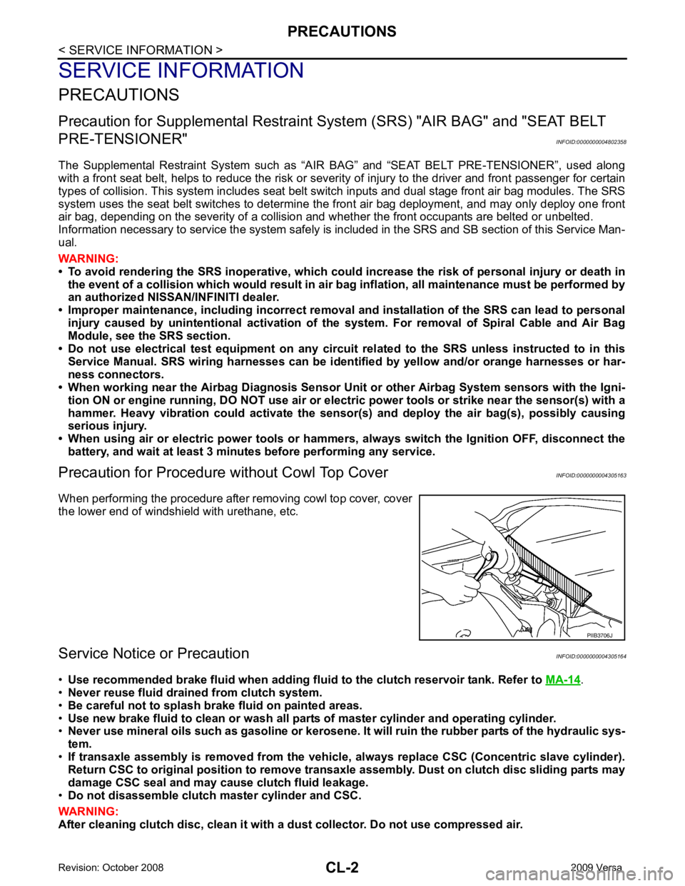
When performing the procedure after removing cowl top cover, cover
the lower end of windshield with urethane, etc.
Service Notice or Precaution INFOID:0000000004305164
• Use recommended brake fluid when adding flui d to the clutch reservoir tank. Refer to MA-14 .
• Never reuse fluid drained from clutch system.
• Be careful not to splash brake fluid on painted areas.
• Use new brake fluid to clean or wash all part s of master cylinder and operating cylinder.
• Never use mineral oils such as gasoline or kerosene. It will ruin the rubber parts of the hydraulic sys-
tem.
• If transaxle assembly is removed from the vehicle , always replace CSC (Concentric slave cylinder).
Return CSC to original position to remove transaxle assembly. Dust on clutch disc sliding parts may
damage CSC seal and may cause clutch fluid leakage.
• Do not disassemble clutch master cylinder and CSC.
WARNING:
After cleaning clutch disc, clean it with a dust collector. Do not use compressed air. PIIB3706J
Page 880 of 4331

CL-8EM-195CL-12CL-15EM-216SUSPECTED PARTS (Possible cause)
CLUTCH PEDAL (Inspection and adjustment)
CLUTCH LINE (Air in line)
ENGINE MOUNTING (Loose)
CSC (Concentric slave cylinder) (Worn, dirty or damaged)
CLUTCH DISC (Out of true)
CLUTCH DISC (Runou t is excessive)
CLUTCH DISC (Lining broken)
CLUTCH DISC (Dirty or burned)
CLUTCH DISC (Oily)
CLUTCH DISC (Worn out)
CLUTCH DISC (Hardened)
CLUTCH DISC (Lack of spline grease)
DIAPHRAGM SPRING (Damaged)
DIAPHRAGM SPRING (Out of tip alignment)
PRESSURE PLATE (Distortion)
FLYWHEEL (Distortion)
Symptom Clutch grabs/chatters 1 2 2 2 2 2
Clutch pedal spongy 1
Clutch noisy 1
Clutch slips 1 2 2 3 4 5
Clutch does not disengage 1 2 5 5 5 5 5 5 6 6 7
Page 891 of 4331
CL
N
O P
CLUTCH DISC, CLUTCH COVER AND FLYWHEEL
Removal and Installation INFOID:0000000004305174
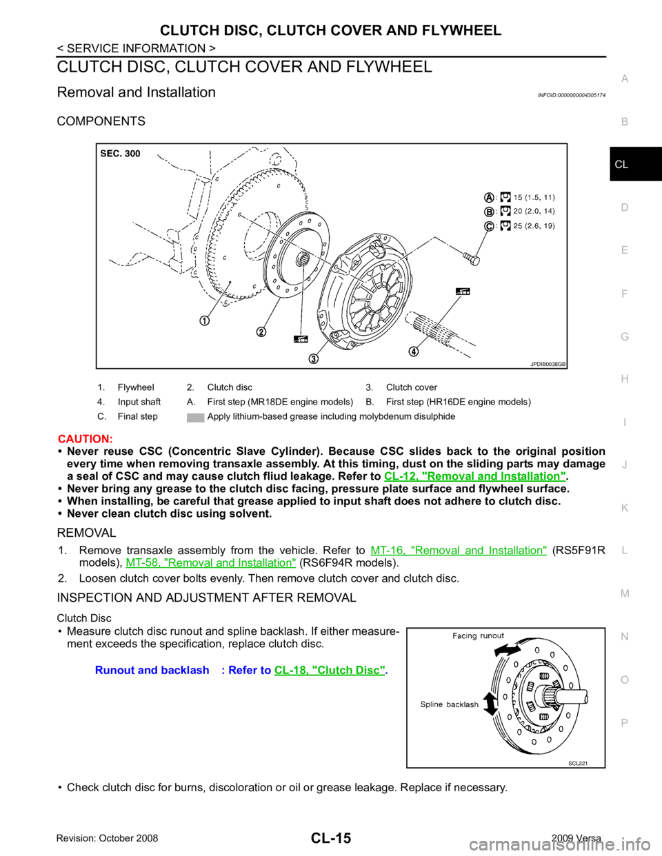
COMPONENTS
CAUTION:
• Never reuse CSC (Concentric Slave Cylinder). B ecause CSC slides back to the original position
every time when removing transaxle assembly. At th is timing, dust on the sliding parts may damage
a seal of CSC and may cause clut ch fliud leakage. Refer to CL-12, " Removal and Installation " .
• Never bring any grease to the clutch disc faci ng, pressure plate surface and flywheel surface.
• When installing, be careful that grease applied to input shaft does not adhere to clutch disc.
• Never clean clutch disc using solvent.
REMOVAL 1. Remove transaxle assembly from the vehicle. Refer to MT-16, " Removal and Installation " (RS5F91R
models), MT-58, " Removal and Installation " (RS6F94R models).
2. Loosen clutch cover bolts evenly. Then remove clutch cover and clutch disc.
INSPECTION AND ADJUSTMENT AFTER REMOVAL
Clutch Disc • Measure clutch disc runout and spline backlash. If either measure- ment exceeds the specificat ion, replace clutch disc.
• Check clutch disc for burns, discoloration or oil or grease leakage. Replace if necessary.
1. Flywheel 2. Clutch disc 3. Clutch cover
4. Input shaft A. First step (MR18DE engine models) B. First step (HR16DE engine models)
C. Final step Apply lithium-based grease including molybdenum disulphide Clutch Disc " .
Page 898 of 4331
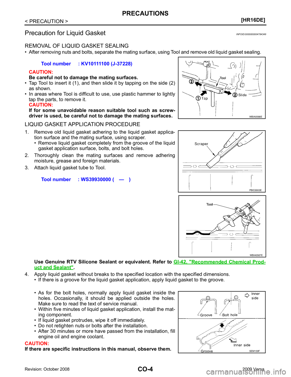
Recommended Chemical Prod-
uct and Sealant " .
4. Apply liquid gasket without breaks to the specif ied location with the specified dimensions.
• If there is a groove for the liquid gasket application, apply liquid gasket to the groove.
• As for the bolt holes, normally apply liquid gasket inside the holes. Occasionally, it should be applied outside the holes.
Make sure to read the text of service manual.
• Within five minutes of liquid gasket application, install the mat-
ing component.
• If liquid gasket protrudes, wipe it off immediately.
• Do not retighten nuts or bolts after the installation.
• After 30 minutes or more have passed from the installation, fill engine oil and engine coolant.
CAUTION:
If there are specific instructions in this manual, observe them.
Tool number : KV10111100 (J-37228)
SEM159F
Page 917 of 4331
CO
NP
O
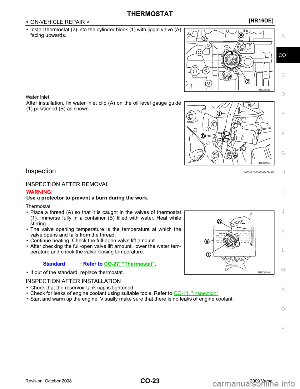
• Install thermostat (2) into the cylinder block (1) with jiggle valve (A)
facing upwards.
Water Inlet. After installation, fix water inlet clip (A) on the oil level gauge guide
(1) positioned (B) as shown.
Inspection INFOID:0000000004784366
INSPECTION AFTER REMOVAL WARNING:
Use a protector to prevent a burn during the work.
Thermostat • Place a thread (A) so that it is caught in the valves of thermostat (1). Immerse fully in a container (B) filled with water. Heat while
stirring.
• The valve opening temperature is the temperature at which the valve opens and falls from the thread.
• Continue heating. Check the full-open valve lift amount.
• After checking the full-open valve lift amount, lower the water tem- perature and check the valve closing temperature.
• If out of the standard, replace thermostat.
INSPECTION AFTER INSTALLATION • Check that the reservoir tank cap is tightened.
• Check for leaks of engine coolant using suitable tools. Refer to CO-11, " Inspection " .
• Start and warm up the engine. Visually make sure that there is no leaks of engine coolant. PBIC3755E
Thermostat " .
Page 923 of 4331
![NISSAN TIIDA 2009 Service Repair Manual PRECAUTIONS
CO-29
< SERVICE INFORMATION >
[MR18DE] C
D E
F
G H
I
J
K L
M A CO
NP
O
Precaution for Liquid Gasket
INFOID:0000000004305229
REMOVAL OF LIQUID GASKET SEALING • After removing nuts and bol](/manual-img/5/57398/w960_57398-922.png "NISSAN TIIDA 2009 Service Repair Manual PRECAUTIONS
CO-29
< SERVICE INFORMATION >
[MR18DE] C
D E
F
G H
I
J
K L
M A CO
NP
O
Precaution for Liquid Gasket
INFOID:0000000004305229
REMOVAL OF LIQUID GASKET SEALING • After removing nuts and bol")
PRECAUTIONS
CO-29
< SERVICE INFORMATION >
[MR18DE] C
D E
F
G H
I
J
K L
M A CO
NP
O
Precaution for Liquid Gasket
INFOID:0000000004305229
REMOVAL OF LIQUID GASKET SEALING • After removing nuts and bolts, separate the mating surface, using Tool and remove old liquid gasket sealing.
CAUTION:
Be careful not to damage the mating surfaces.
• Tap Tool to insert it (1), and then slide it by tapping on the side (2)
as shown.
• In areas where Tool is difficult to use, use plastic hammer to lightly
tap the parts, to remove it.
CAUTION:
If for some unavoidable reason suitable tool such as screw-
driver is used, be careful not to damage the mating surfaces.
LIQUID GASKET APPLICATION PROCEDURE 1. Remove old liquid gasket adhering to the liquid gasket applica- tion surface and the mating surface, using scraper.
• Remove liquid gasket completely from the groove of the liquid gasket application surface, bolts, and bolt holes.
2. Thoroughly clean the mating surfaces and remove adhering moisture, grease and foreign materials.
3. Attach liquid gasket tube to Tool.
Use Genuine RTV Silicone Seal ant or equivalent. Refer to GI-42, " Recommended Chemical Prod-
uct and Sealant " .
4. Apply liquid gasket without breaks to the spec ified location with the specified dimensions.
• If there is a groove for the liquid gasket application, apply liquid gasket to the groove.
• As for the bolt holes, normally apply liquid gasket inside the holes. Occasionally, it should be applied outside the holes.
Make sure to read the text of service manual.
• Within five minutes of liquid gasket application, install the mat-
ing component.
• If liquid gasket protrudes, wipe it off immediately.
• Do not retighten nuts or bolts after the installation.
• After 30 minutes or more have passed from the installation, fill engine oil and engine coolant.
CAUTION:
If there are specific instructions in this manual, observe them.
Tool number : KV10111100 (J-37228)
WBIA0566E
Tool number : WS39930000 ( — )
PBIC0003E
WBIA0567E
SEM159F
Page 939 of 4331
CO
NP
O
THERMOSTAT
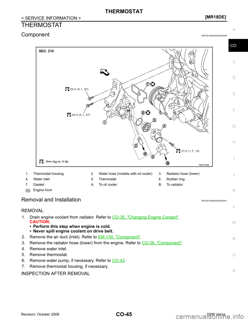
Component INFOID:0000000004305246
Removal and Installation INFOID:0000000004305247
REMOVAL 1. Drain engine coolant from radiator. Refer to CO-35, " Changing Engine Coolant " .
CAUTION:
• Perform this step when engine is cold.
• Never spill engine coolant on drive belt.
2. Remove the air duct (inlet). Refer to EM-139, " Component " .
3. Remove the radiator hose (lower) from the engine. Refer to CO-38, " Component " .
4. Remove water inlet.
5. Remove thermostat.
6. Remove water pump, if necessary. Refer to CO-43 .
7. Remove thermostat housing, if necessary.
INSPECTION AFTER REMOVAL 1. Thermostat housing 2. Water hose (models with oil cooler) 3. Radiator hose (lower)
4. Water inlet 5. Thermostat 6. Rubber ring
7. Gasket A. To oil cooler B. To radiator Engine front