2009 NISSAN TIIDA ECO mode
[x] Cancel search: ECO modePage 371 of 4331
AT-366< SERVICE INFORMATION >
ASSEMBLY
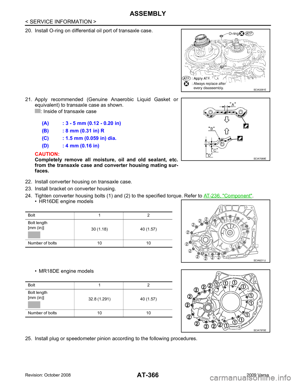
20. Install O-ring on differential oil port of transaxle case.
21. Apply recommended (Genuine Anaerobic Liquid Gasket or equivalent) to transaxle case as shown.
: Inside of transaxle case
CAUTION:
Completely remove all moisture, oil and old sealant, etc.
from the transaxle case and converter housing mating sur-
faces.
22. Install converter housing on transaxle case.
23. Install bracket on converter housing.
24. Tighten converter housing bolts (1) and (2) to the specified torque. Refer to AT-236, " Component " .
• HR16DE engine models
• MR18DE engine models
25. Install plug or speedometer pinion according to the following procedures. SCIA3281E
(A) : 3 - 5 mm (0.12 - 0.20 in)
(B) : 8 mm (0.31 in) R
(C) : 1.5 mm (0.059 in) dia.
(D) : 4 mm (0.16 in) SCIA7089E
Bolt 1 2
Bolt length
[mm (in)] 30 (1.18) 40 (1.57)
Number of bolts 10 10 SCIA6211J
Bolt 1 2
Bolt length
[mm (in)] 32.8 (1.291) 40 (1.57)
Number of bolts 10 10 SCIA7970E
Page 377 of 4331

.
Vehicle Speed at Which Gear Shifting Occurs INFOID:0000000004807935
HR16DE engine models
MR18DE engine models
• At half throttle, the accelerator opening is 4/8 of the full opening.
Vehicle Speed at When Lock-up Occurs/Releases INFOID:0000000004807936
HR16DE engine models
MR18DE engine models Engine
HR16DE MR18DE
Automatic transaxle model RE4F03B
Automatic transaxle assembly Model code number 3CX3D, 3CX3E 3CX0D
Transaxle gear ratio 1st 2.861
2nd 1.562
3rd 1.000
4th 0.697
Reverse 2.310
Final drive 4.072
Recommended fluid Genuine NISSAN Matic D ATF (Conti
nental U.S. and Alaska) or
Canada NISSAN Automatic Transmission Fluid*
Fluid capacity [ (US qt, Imp qt)] 7.7 (8-1/8, 6-3/4) 7.9 (8-3/8, 7)Throttle position
Vehicle speed km/h (MPH)
D 1
→ D 2 D2 → D 3 D3 → D 4 D4 → D 3 D3 → D 2 D2 → D 1
Full throttle 49 - 57
(31 - 35) 93 - 101
(58 - 62) 148 - 156
(92 - 96) 144 - 152
(90 - 94) 82 - 90
(51 - 55) 39 - 47
(25 - 29)
Half throttle 35 - 43
(22 - 26) 59 - 67
(37 - 41) 117 - 125
(73 - 77) 59 - 67
(37 - 41) 34 - 42
(22 - 26) 15 - 23
(10 - 14)
Throttle position Vehicle speed km/h (MPH)
D 1 → D 2 D2 → D 3 D3 → D 4 D4 → D 3 D3 → D 2 D2 → D 1
Full throttle 51 - 59
(32 - 37) 97 - 105
(60 - 65) 154 - 162
(96 - 101) 150 - 158
(93 - 98) 87 - 95
(54 - 59) 40 - 48
(25 - 30)
Half throttle 34 - 42
(21 - 26) 62 - 70
(39 - 43) 124 - 132
(77 - 82) 69 - 77
(43 - 48) 36 - 44
(22 - 27) 19 - 27
(12 - 17) Throttle position Selector lever position
Vehicle speed km/h (MPH)
Lock-up ON Lock-up OFF
2.0/8 “D” position 73 - 81 (46
- 50) 49 - 57 (31 - 35)
“D” position (OD OFF) 86 - 94 (53 - 58) 82 - 90 (51 - 55)
Throttle position Selector lever position Vehicle speed km/h (MPH)
Lock-up ON Lock-up OFF
2.0/8 “D” position 86 - 94 (53
- 58) 59 - 67 (37 - 42)
“D” position (OD OFF) 86 - 94 (53 - 58) 83 - 91 (52 - 57)
Page 433 of 4331
AV
N
O P
Bluetooth Control Unit
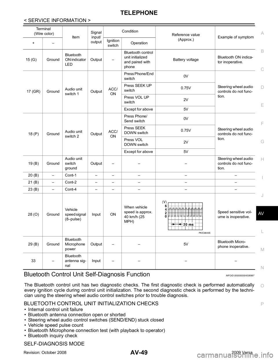
Self-Diagnosis Function INFOID:0000000004306987
The Bluetooth control unit has two diagnostic checks. The first diagnostic check is performed automatically
every ignition cycle during control unit initialization. The second diagnostic check is performed by the techni-
cian using the steering wheel audio control switches prior to trouble diagnosis.
BLUETOOTH CONTROL UNIT INITIALIZATION CHECKS
• Internal control unit failure
• Bluetooth antenna connection open or shorted
• Steering wheel audio control swit ches (SEND/END) stuck closed
• Vehicle speed pulse count
• Bluetooth Microphone connection test (with playback to operator)
• Bluetooth inquiry check
SELF-DIAGNOSIS MODE 15 (G) Ground
Bluetooth
ON indicator
LED Output – Bluetooth control
unit initialized
and paired with
phone Battery voltage
Bluetooth ON indica-
tor inoperative.
17 (GR) Ground Audio unit
switch 1 OutputACC/
ON Press Phone/End
switch 0V
Steering wheel audio
controls do not func-
tion.
Press SEEK UP
switch 0.75V
Press VOL UP
switch 2V
Except for above 5V
18 (P) Ground Audio unit
switch 2 OutputACC/
ON Press Phone/
Send switch 0V
Steering wheel audio
controls do not func-
tion.
Press SEEK
DOWN switch 0.75V
Press VOL
DOWN switch 2V
Except for above 5V
19 (B) Ground Audio unit
switch
ground Output – – – Steering wheel audio
controls do not func-
tion.
20 (B) – Cont-1 – – – – –
21 (B) – Cont-2 – – – – –
23 (B) – Cont-4 – – – – –
28 (O) Ground Vehicle
speed signal
(8–pulse) Input ON When vehicle
speed is approx.
40 km/h (25
MPH) Speed sensitive vol-
ume is inoperative.
29 (B) Ground Bluetooth
Microphone
power Output – – 5V
Bluetooth Micro-
phone inoperative.
33 – Bluetooth
antenna sig-
nal Input – – – –
Terminal
(Wire color) ItemSignal
input/
output Condition
Reference value
(Approx.) Example of symptom
+ – Ignition
switch Operation
Page 434 of 4331
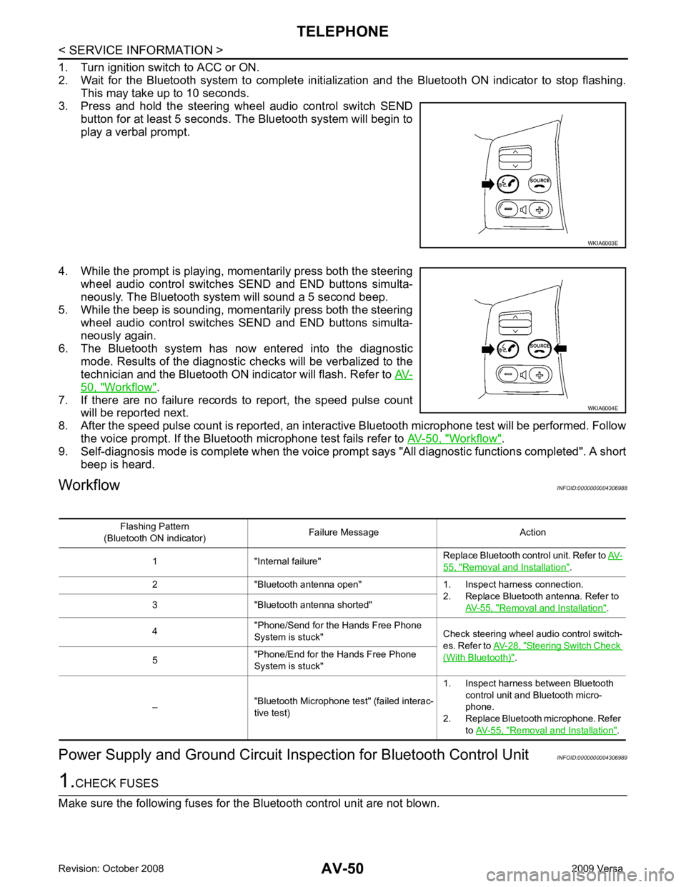
50, " Workflow " .
7. If there are no failure records to report, the speed pulse count will be reported next.
8. After the speed pulse count is reported, an intera ctive Bluetooth microphone test will be performed. Follow
the voice prompt. If the Bluetooth microphone test fails refer to AV-50, " Workflow " .
9. Self-diagnosis mode is complete when the voice prom pt says "All diagnostic functions completed". A short
beep is heard.
Workflow INFOID:0000000004306988
Power Supply and Ground Circuit Ins pection for Bluetooth Control Unit INFOID:0000000004306989 WKIA6004E
55, " Removal and Installation " .
2 "Bluetooth antenna open" 1. Inspect harness connection. 2. Replace Bluetooth antenna. Refer to AV-55, " Removal and Installation " .
3 "Bluetooth antenna shorted"
4 "Phone/Send for the Hands Free Phone
System is stuck" Check steering wheel audio control switch-
es. Refer to AV-28, " Steering Switch Check
(With Bluetooth) " .
5 "Phone/End for the Hands Free Phone
System is stuck"
– "Bluetooth Microphone test" (failed interac-
tive test) 1. Inspect harness between Bluetooth
control unit and Bluetooth micro-
phone.
2. Replace Bluetooth microphone. Refer to AV-55, " Removal and Installation " .
Page 447 of 4331
BCS
N
O P
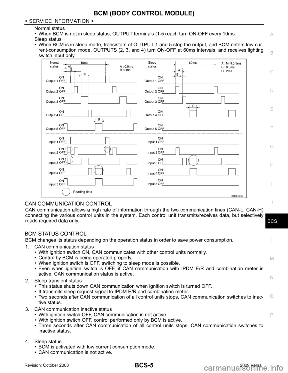
Normal status
• When BCM is not in sleep status, OUTPUT te rminals (1-5) each turn ON-OFF every 10ms.
Sleep status
• When BCM is in sleep mode, transistors of OUTP UT 1 and 5 stop the output, and BCM enters low-cur-
rent-consumption mode. OUTPUTS (2, 3, and 4) turn ON-OFF at 60ms intervals, and receives lighting
switch input only.
CAN COMMUNICATION CONTROL CAN communication allows a high rate of information through the two communication lines (CAN-L, CAN-H)
connecting the various control units in the system. Each control unit transmits/receives data, but selectively
reads required data only.
BCM STATUS CONTROL BCM changes its status depending on the operation stat us in order to save power consumption.
1. CAN communication status • With ignition switch ON, CAN communicates with other control units normally.
• Control by BCM is being operated properly.
• When ignition switch is OFF, switching to sleep mode is possible.
• Even when ignition switch is OFF, if CAN co mmunication with IPDM E/R and combination meter is
active, CAN communication status is active.
2. Sleep transient status • This status shuts down CAN communication when ignition switch is turned OFF.
• It transmits sleep request signal to IPDM E/R and combination meter.
• Two seconds after CAN communication of all control units stops, CAN communication switches to inac-
tive status.
3. CAN communication inactive status • With ignition switch OFF, CAN communication is not active.
• With ignition switch OFF, control performed only by BCM is active.
• Three seconds after CAN communication of all cont rol units stops, CAN communication switches to
inactive status.
4. Sleep status • BCM is activated with low current consumption mode.
• CAN communication is not active.
Page 502 of 4331

BL
N
O P
1: With Intelligent Key
2: Without Intelligent Key
3: Hatchback without Intelligent Key
4: Sedan without Intelligent Key
5: Hatchback
6: Sedan
7: With power door locks
8: With power windows
Work Flow INFOID:0000000004304994
1. Check the symptom and customer's requests.
2. Understand the outline of system. Refer to BL-23, " System Description " .
3. According to the trouble diagnosis chart, repair or replace the cause of the malfunction. Refer to BL-119," Trouble Diagnosis Symptom Chart " .
4. Does power door lock system operate normally? OK: GO TO 5, NG: GO TO 3.
5. Inspection End.
CONSULT-III Function (BCM) INFOID:0000000004304995
CONSULT-III can display each diagnostic item using the diagnostic test modes shown following. 65
7
SBAll door lock actuators
(lock) Output OFFOFF (neutral) 0V
ON (lock) Battery voltage
66 7
GFront door lock actua-
tor RH, rear door lock
actuators LH/RH (un-
lock) Output OFFOFF (neutral) 0V
ON (unlock) Battery voltage
67 B Ground Input ON — 0V
68 8
LPower window power
supply (RAP) Output —Ignition switch ON Battery voltage
Within 45 seconds after igni-
tion switch OFF Battery voltage
More than 45 seconds after ig-
nition switch OFF 0V
When front door LH or RH is
open or power window timer
operates 0V
69 8
P Battery power supply
OutputOFF
— Battery voltage
70 Y Battery power supply Input OFF — Battery voltage
Terminal
Wire
color Signal name Signal
input/
output Measuring condition
Reference value or waveform
(Approx.)
Ignition
switch Operation or condition
Page 521 of 4331
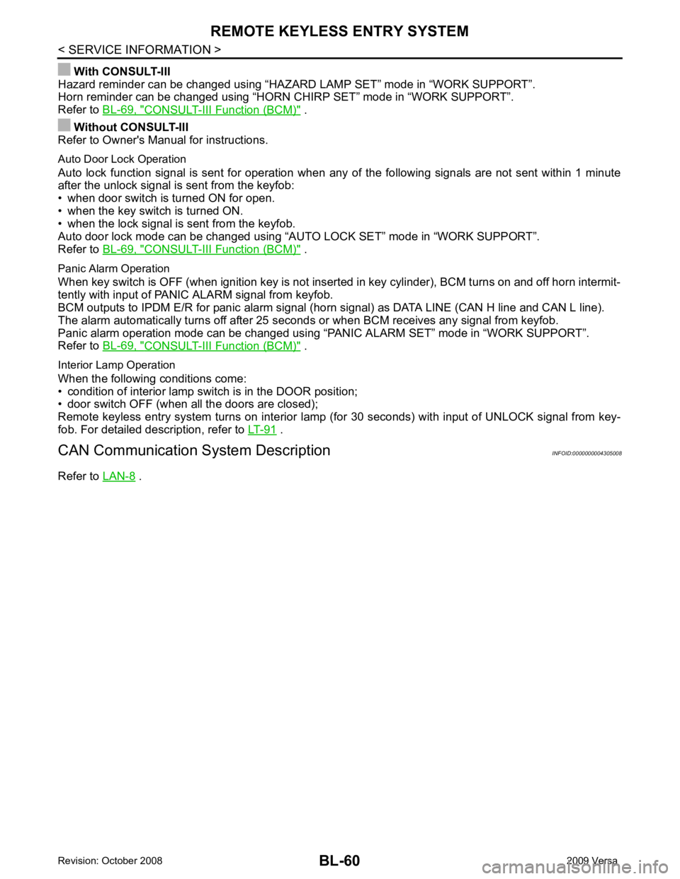
CONSULT-III Function (BCM) " .
Without CONSULT-III
Refer to Owner's Manual for instructions.
Auto Door Lock Operation
Auto lock function signal is sent for operation when any of the following signals are not sent within 1 minute
after the unlock signal is sent from the keyfob:
• when door switch is turned ON for open.
• when the key switch is turned ON.
• when the lock signal is sent from the keyfob.
Auto door lock mode can be changed using “AUT O LOCK SET” mode in “WORK SUPPORT”.
Refer to BL-69, " CONSULT-III Function (BCM) " .
Panic Alarm Operation
When key switch is OFF (when ignition key is not inserted in key cylinder), BCM turns on and off horn intermit-
tently with input of PANIC ALARM signal from keyfob.
BCM outputs to IPDM E/R for panic alarm signal (horn signal) as DATA LINE (CAN H line and CAN L line).
The alarm automatically turns off after 25 seconds or when BCM receives any signal from keyfob.
Panic alarm operation mode can be changed using “P ANIC ALARM SET” mode in “WORK SUPPORT”.
Refer to BL-69, " CONSULT-III Function (BCM) " .
Interior Lamp Operation
When the following conditions come:
• condition of interior lamp switch is in the DOOR position;
• door switch OFF (when all the doors are closed);
Remote keyless entry system turns on interior lamp (for 30 seconds) with input of UNLOCK signal from key-
fob. For detailed description, refer to LT-91 .
CAN Communication System Description INFOID:0000000004305008
Refer to LAN-8 .
Page 530 of 4331
BL
N
O P
1: With Intelligent Key
2: Without Intelligent Key
3: Hatchback without Intelligent Key
4: Sedan without Intelligent Key
5: Hatchback
6: Sedan
7: With power door locks
8: With power windows
How to Perform Trouble Diagnosis INFOID:0000000004305012
1. Confirm the symptom or customer complaint.
2. Understand operation, description and function description. Refer to BL-58, " System Description " .
3. Perform the Preliminary Check. Refer to LT-11, " Preliminary Check " .
4. Check symptom and repair or replace the component.
5. Does the remote keyless entry system operate normally? If YES, GO TO 6. If NO, GO TO 4.
6. Inspection End.
Preliminary Check INFOID:0000000004305013
CHECK BCM CONFIGURATION Configuration " .
OK or NG OK >> Refer to
BL-71, " Work Flow " .
NG >> Change BCM configuration for "KEYLESS ENTRY" to "WITH". Refer to BCS-18, " Configuration " .
CONSULT-III Function (BCM) INFOID:0000000004305014
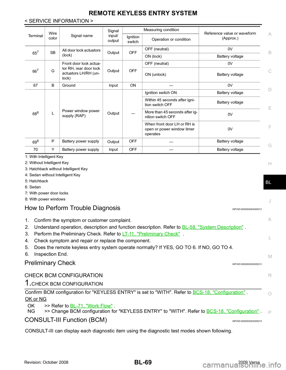
CONSULT-III can display each diagnostic item using the diagnostic test modes shown following. 65
7
SBAll door lock actuators
(lock) Output OFFOFF (neutral) 0V
ON (lock) Battery voltage
66 7
GFront door lock actua-
tor RH, rear door lock
actuators LH/RH (un-
lock) Output OFFOFF (neutral) 0V
ON (unlock) Battery voltage
67 B Ground Input ON — 0V
68 8
LPower window power
supply (RAP) Output —Ignition switch ON Battery voltage
Within 45 seconds after igni-
tion switch OFF Battery voltage
More than 45 seconds after ig-
nition switch OFF 0V
When front door LH or RH is
open or power window timer
operates 0V
69 8
P Battery power supply
OutputOFF
— Battery voltage
70 Y Battery power supply Input OFF — Battery voltage
Terminal
Wire
color Signal name Signal
input/
output Measuring condition
Reference value or waveform
(Approx.)
Ignition
switch Operation or condition