Page 4209 of 4331
SRS
N
O P
III
HOW TO ERASE SELF-DIAGNOSIS RESULTS After a malfunction is repaired, turn the ignition switch OFF for at least one second, then back ON. Diagnosis
mode returns to the User mode. At that time, the self-diagnostic result is cleared.
SRS Operation Check INFOID:0000000004307189
DIAGNOSTIC PROCEDURE 1
Checking SRS Operation Using “AIR BAG” Warning Lamp—User Mode 1. Turn the ignition switch from OFF to ON, and check that the air bag warning lamp blinks.
2. Compare the SRS air bag warning lamp blinking pattern with the examples.
Page 4215 of 4331

SRS
N
O P
2. Touch “TROUBLE DIAG RECORD”.
NOTE:
With “TROUBLE DIAG RECORD”, di agnosis results previously erased by a reset operation can be
displayed.
3. Diagnostic code is displayed on “TROUBLE DIAG RECORD”.
4. Touch “PRINT”.
5. Compare diagnostic codes to "CONSULT-III Diagnos tic Code Chart ("SELF-DIAG [PAST]" or "TROUBLE
DIAG RECORD")".
6. Touch “BACK” key of CONSULT- III until “SELECT SYSTEM” appears.
7. Turn ignition switch OFF, then turn off and disconnect CONSULT-III, and both battery cables.
8. Repair the system as outlined by the “Repair orde r” in “Intermittent Malfunction Diagnostic Code Chart”,
that corresponds to the self-diagnostic result. For r eplacement procedure of component parts, refer to the
Removal and Installation procedure for the appropriate component.
9. Go to "DIAGNOSTIC PROCEDURE 3", for final checking.
CONSULT-III Diagnostic Code Chart ("SELF-DI AG [PAST]" or "TROUBLE DIAG RECORD")
Diagnostic item Explanation Repair order
Recheck SRS at each replacement
NO DTC IS DETECTED When malfunction is
indicated by the “AIR
BAG” warning lamp in
User mode. • Low battery voltage (L
ess than 9V) • Go to "DIAGNOSTIC PROCEDURE
3" .
• Self-diagnostic result “SELF-DIAG [PAST]” (previously stored in the
memory) might not be erased after
repair.
• Intermittent malfunction has been detected in the past. • Go to "DIAGNOSTIC PROCEDURE
4" .
• Go to "DIAGNOSTIC PROCEDURE
5" .
• No malfunction is detected. —
DRIVER AIRBAG MODULE [OPEN]
[B1049] or [B1054] Driver air bag module circuit is open (including the spiral ca-
ble). 1. Visually check the wiring harness
connection.
2. Replace the harness if it has visi- ble damage.
3. Replace driver air bag module.
4. Replace the spiral cable.
5. Replace the air bag diagnosis
sensor unit.
6. Replace the related harness.
DRIVER AIRBAG MODULE
[VB-SHORT]
[B1050] or [B1055] Driver air bag module circuit is shorted to some power supply
circuit (including the spiral cable).
DRIVER AIRBAG MODULE [GND-SHORT]
[B1051] or [B1056] Driver air bag module circuit is shorted to ground (including
the spiral cable).
DRIVER AIRBAG MODULE [SHORT]
[B1052] or [B1057] Driver air bag module circuits are shorted to each other.
ASSIST A/B MODULE [OPEN]
[B1065] or [B1070] Front passenger air bag module circuit is open. 1. Visually check the wiring harness
connection.
2. Replace the harness if it has visi-
ble damage.
3. Replace front passenger air bag module.
4. Replace the air bag diagnosis sensor unit.
5. Replace the related harness.
ASSIST A/B MODULE
[VB-SHORT]
[B1066] or [B1071] Front passenger air bag module circuit is shorted to some
power supply circuit.
ASSIST A/B MODULE [GND-SHORT]
[B1067] or [B1072] Front passenger air bag module circuit is shorted to ground.
ASSIST A/B MODULE [SHORT]
[B1068] or [B1073] Front passenger air bag module circuits are shorted to each
other.
Page 4278 of 4331

TROUBLE DIAGNOSES
WT-13
< SERVICE INFORMATION >
C
D
F
G H
I
J
K L
M A
B WT
N
O P
6. Inflate all tires to proper pressure. Refer to
WT-27, " Tire " .
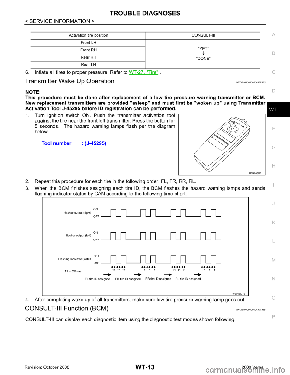
Transmitter Wake Up Operation INFOID:0000000004307325
NOTE:
This procedure must be done after replacement of a low tire pressure warning transmitter or BCM.
New replacement transmitters are provided "asleep" and must first be "woken up" using Transmitter
Activation Tool J-45295 before ID registration can be performed.
1. Turn ignition switch ON. Push the transmitter activation tool against the tire near the front left transmitter. Press the button for
5 seconds. The hazard warning lamps flash per the diagram
below.
2. Repeat this procedure for each tire in the following order: FL, FR, RR, RL.
3. When the BCM finishes assigning each tire ID, the BCM flashes the hazard warning lamps and sends flashing indicator status by CAN according to the following time chart.
4. After completing wake up of all transmitters, make sure low tire pressure warning lamp goes out.
CONSULT-III Function (BCM) INFOID:0000000004307326
CONSULT-III can display each diagnostic item using the diagnostic test modes shown following. Activation tire position CONSULT-III
Front LH “YET”↓
“DONE”
Front RH
Rear RH Rear LH Tool number : (J-45295)
LEIA0036E
WEIA0177E
Page 4281 of 4331

OK >> GO TO 4.
NG >> Repair or replace damaged parts. OK >> Carry out self-diagnosis.
NG >> Replace battery in transmitter activation tool.
Self-Diagnosis (With CONSULT-III) INFOID:0000000004307329
DESCRIPTION
During driving, the tire pressure monitoring system receives the signal transmitted from the transmitter
installed in each wheel, and turns on the low tire pressure warning lamp when the tire pressure becomes low.
The control unit (BCM) for this system has pressure judgement and self-diagnosis functions.
FUNCTION
When the tire pressure monitoring syst em detects low inflation pressure or an internal malfunction, the low tire
pressure warning lamp in the combination meter comes on. The malfunction location is indicated by the low
tire pressure warning lamp flashing and the buzzer sounding.
CONSULT-III Application to Tire Pressure Monitoring System
× : Applicable
– : Not applicable
Self-Diagnostic Results Mode ITEM SELF-DIAGNOSTIC RESULTS DATA MONITOR
Front - Left transmitter × ×
Front - Right transmitter × ×
Rear - Left transmitter × ×
Rear - Right transmitter × ×
Warning lamp — ×
Vehicle speed × ×
Buzzer (in combination meter) — ×
CAN Communication × × 8, " System Description " .