2009 NISSAN TIIDA engine control system
[x] Cancel search: engine control systemPage 1831 of 4331
EC
NP
O
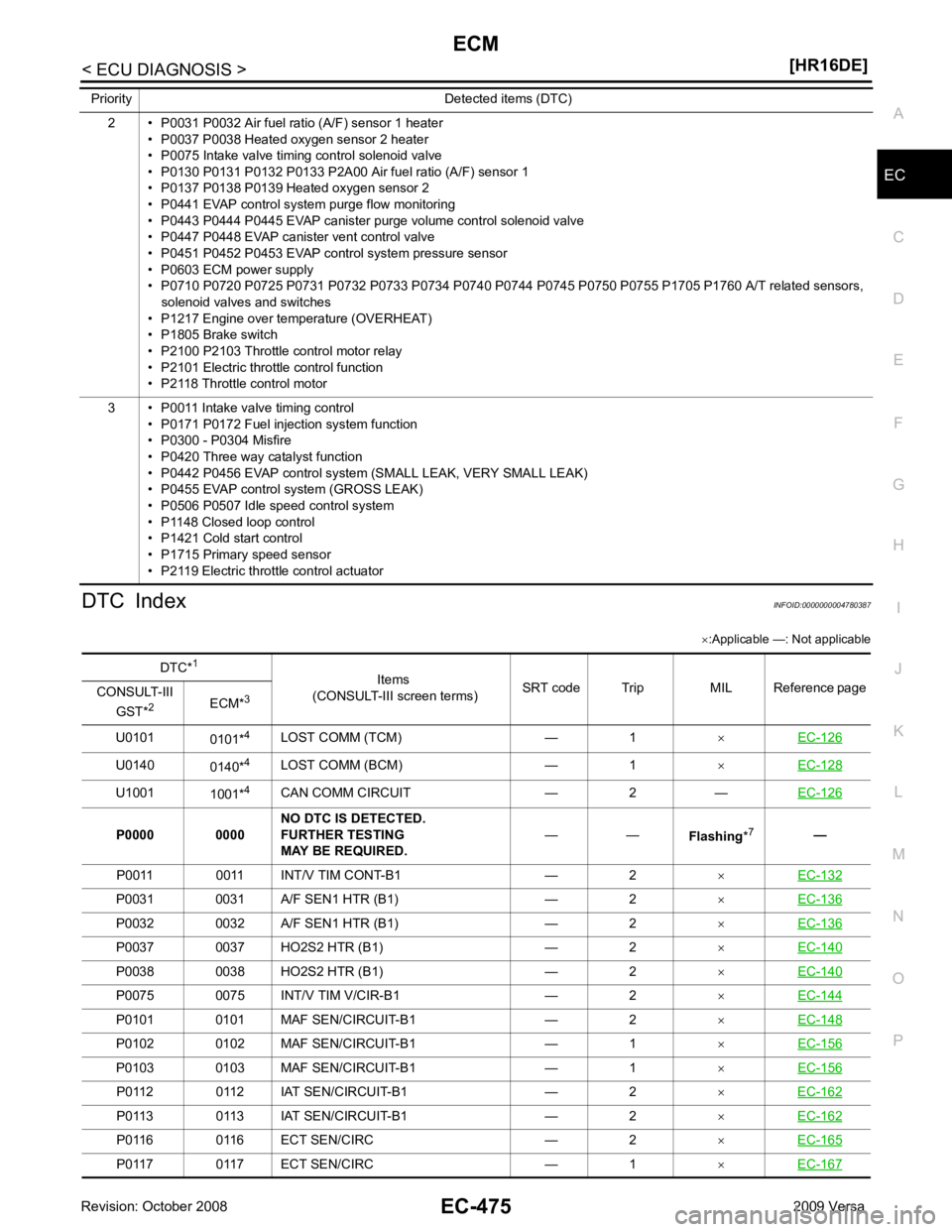
DTC Index
INFOID:0000000004780387
× :Applicable —: Not applicable
2 • P0031 P0032 Air fuel ratio (A/F) sensor 1 heater
• P0037 P0038 Heated oxygen sensor 2 heater
• P0075 Intake valve timing control solenoid valve
• P0130 P0131 P0132 P0133 P2A00 Air fuel ratio (A/F) sensor 1
• P0137 P0138 P0139 Heated oxygen sensor 2
• P0441 EVAP control system purge flow monitoring
• P0443 P0444 P0445 EVAP canister purge volume control solenoid valve
• P0447 P0448 EVAP canister vent control valve
• P0451 P0452 P0453 EVAP control system pressure sensor
• P0603 ECM power supply
• P0710 P0720 P0725 P0731 P0732 P0733 P0734 P0740 P0744 P0745 P0750 P0755 P1705 P1760 A/T related sensors,
solenoid valves and switches
• P1217 Engine over temperature (OVERHEAT)
• P1805 Brake switch
• P2100 P2103 Throttle control motor relay
• P2101 Electric throttle control function
• P2118 Throttle control motor
3 • P0011 Intake valve timing control • P0171 P0172 Fuel injection system function
• P0300 - P0304 Misfire
• P0420 Three way catalyst function
• P0442 P0456 EVAP control system (SMALL LEAK, VERY SMALL LEAK)
• P0455 EVAP control system (GROSS LEAK)
• P0506 P0507 Idle speed control system
• P1148 Closed loop control
• P1421 Cold start control
• P1715 Primary speed sensor
• P2119 Electric throttle control actuator
Priority Detected items (DTC) DTC*
1
Items
(CONSULT-III screen terms) SRT code Trip MIL Reference page
CONSULT-III
GST* 2
ECM*3
U0101 0101*4
LOST COMM (TCM) — 1 ×EC-126 U0140
0140*4
LOST COMM (BCM) — 1 ×EC-128 U1001
1001*4
CAN COMM CIRCUIT — 2 — EC-126P0031 0031 A/F SEN1 HTR (B1) — 2
×EC-136 P0032 0032 A/F SEN1 HTR (B1) — 2
×EC-136 P0037 0037 HO2S2 HTR (B1) — 2
×EC-140 P0038 0038 HO2S2 HTR (B1) — 2
×EC-140 P0075 0075 INT/V TIM V/CIR-B1 — 2
×EC-144 P0101 0101 MAF SEN/CIRCUIT-B1 — 2
×EC-148 P0102 0102 MAF SEN/CIRCUIT-B1 — 1
×EC-156 P0103 0103 MAF SEN/CIRCUIT-B1 — 1
×EC-156 P0112 0112 IAT SEN/CIRCUIT-B1 — 2
×EC-162 P0113 0113 IAT SEN/CIRCUIT-B1 — 2
×EC-162 P0116 0116 ECT SEN/CIRC — 2
×EC-165 P0117 0117 ECT SEN/CIRC — 1
×EC-167
Page 1833 of 4331
EC
NP
O
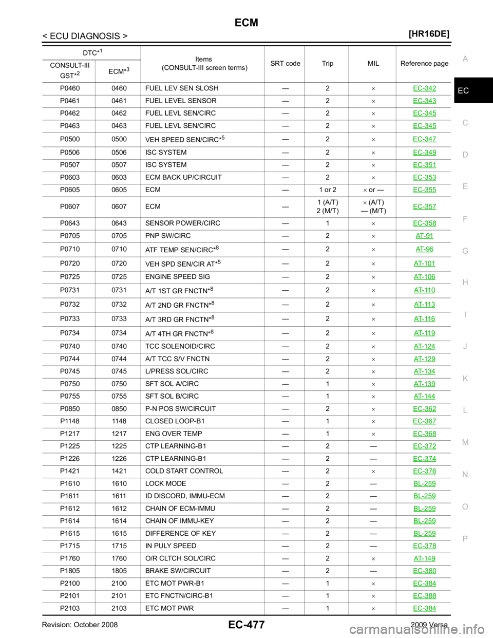
P0460 0460 FUEL LEV SEN SLOSH — 2
×EC-342 P0461 0461 FUEL LEVEL SENSOR — 2
×EC-343 P0462 0462 FUEL LEVL SEN/CIRC — 2
×EC-345 P0463 0463 FUEL LEVL SEN/CIRC — 2
×EC-345 P0500 0500
VEH SPEED SEN/CIRC*5
— 2 ×EC-347 P0506 0506 ISC SYSTEM — 2
×EC-349 P0507 0507 ISC SYSTEM — 2
×EC-351 P0603 0603 ECM BACK UP/CIRCUIT — 2
×EC-353 P0605 0605 ECM — 1 or 2
× or — EC-355 P0607 0607 ECM —
1 (A/T)
2 (M/T) ×
(A/T)
— (M/T) EC-357 P0643 0643 SENSOR POWER/CIRC — 1
×EC-358 P0705 0705 PNP SW/CIRC — 2
×AT-91 P0710 0710
ATF TEMP SEN/CIRC*8
— 2 ×AT-96 P0720 0720
VEH SPD SEN/CIR AT*5
— 2 ×AT-101 P0725 0725 ENGINE SPEED SIG — 2
×AT-106 P0731 0731
A/T 1ST GR FNCTN*8
— 2 ×AT-110 P0732 0732
A/T 2ND GR FNCTN*8
— 2 ×AT-113 P0733 0733
A/T 3RD GR FNCTN*8
— 2 ×AT-116 P0734 0734
A/T 4TH GR FNCTN*8
— 2 ×AT-119 P0740 0740 TCC SOLENOID/CIRC — 2
×AT-124 P0744 0744 A/T TCC S/V FNCTN — 2
×AT-129 P0745 0745 L/PRESS SOL/CIRC — 2
×AT-134 P0750 0750 SFT SOL A/CIRC — 1
×AT-139 P0755 0755 SFT SOL B/CIRC — 1
×AT-144 P0850 0850 P-N POS SW/CIRCUIT — 2
×EC-362 P1148 1148 CLOSED LOOP-B1 — 1
×EC-367 P1217 1217 ENG OVER TEMP — 1
×EC-368 P1225 1225 CTP LEARNING-B1 — 2 —
EC-372P1226 1226 CTP LEARNING-B1 — 2 —
EC-374P1421 1421 COLD START CONTROL — 2
×EC-376 P1610 1610 LOCK MODE — 2 —
BL-259P1611 1611 ID DISCORD, IMMU-ECM — 2 —
BL-259P1612 1612 CHAIN OF ECM-IMMU — 2 —
BL-259P1614 1614 CHAIN OF IMMU-KEY — 2 —
BL-259P1615 1615 DIFFERENCE OF KEY — 2 —
BL-259P1715 1715 IN PULY SPEED — 2 —
EC-378P1760 1760 O/R CLTCH SOL/CIRC — 2
×AT-149 P1805 1805 BRAKE SW/CIRCUIT — 2 —
EC-380P2100 2100 ETC MOT PWR-B1 — 1
×EC-384 P2101 2101 ETC FNCTN/CIRC-B1 — 1
×EC-388 P2103 2103 ETC MOT PWR — 1
×EC-384 DTC*
1
Items
(CONSULT-III screen terms) SRT code Trip MIL Reference page
CONSULT-III
GST* 2
ECM*3
Page 1843 of 4331
EC
NP
O
SYMPTOM DIAGNOSIS
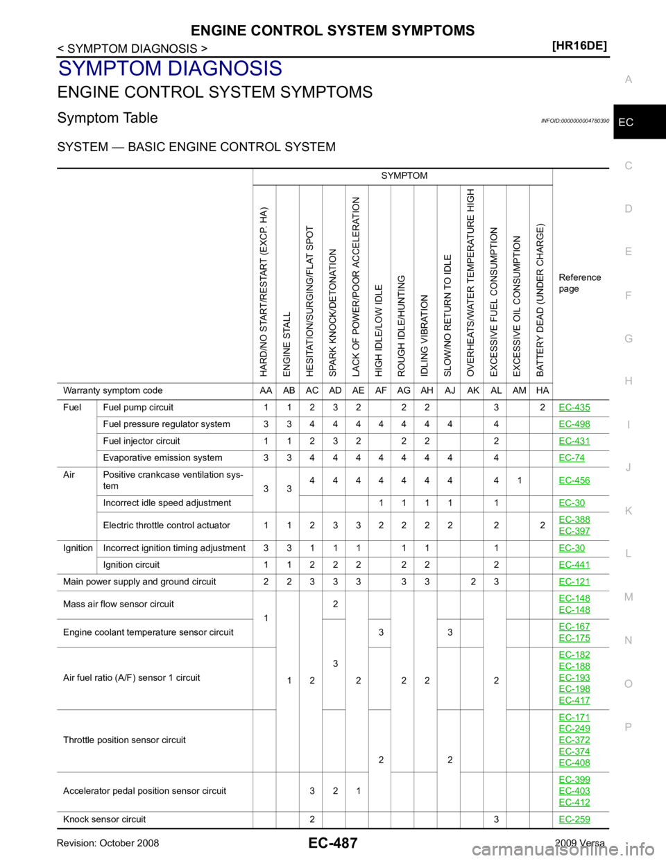
ENGINE CONTROL SYSTEM SYMPTOMS
Symptom Table INFOID:0000000004780390
SYSTEM — BASIC ENGINE CONTROL SYSTEM SYMPTOM
Reference
pageHARD/NO START/RESTART (EXCP. HA)
ENGINE STALL
HESITATION/SURGING/FLAT SPOT
SPARK KNOCK/DETONATION
LACK OF POWER/POOR ACCELERATION
HIGH IDLE/LOW IDLE
ROUGH IDLE/HUNTING
IDLING VIBRATION
SLOW/NO RETURN TO IDLE
OVERHEATS/WATER TEMPERATURE HIGH
EXCESSIVE FUEL CONSUMPTION
EXCESSIVE OIL CONSUMPTION
BATTERY DEAD (UNDER CHARGE)
Warranty symptom code AA AB AC AD AE AF AG AH AJ AK AL AM HA
Fuel Fuel pump circuit 1 1 2 3 2 2 2 3 2 EC-435Fuel pressure regulator system 3 3 4 4 4 4 4 4 4 4
EC-498Fuel injector circuit 1 1 2 3 2 2 2 2
EC-431Evaporative emission system 3 3 4 4 4 4 4 4 4 4
EC-74Air Positive crankcase ventilation sys-
tem 3 34 4 4 4 4 4 4 4 1
EC-456Incorrect idle speed adjustment 1 1 1 1 1
EC-30Electric throttle control actuator 1 1 2 3 3 2 2 2 2 2 2
EC-388 EC-397
Ignition Incorrect ignition timing adjustment 3 3 1 1 1 1 1 1
EC-30Ignition circuit 1 1 2 2 2 2 2 2
EC-441Main power supply and ground circuit 2 2 3 3 3 3 3 2 3
EC-121Mass air flow sensor circuit
1
1 2 2
2 2 2 2 EC-148 EC-148
Engine coolant temperature sensor circuit
33 3
EC-167 EC-175
Air fuel ratio (A/F) sensor 1 circuit
EC-182 EC-188
EC-193
EC-198
EC-417
Throttle position sensor circuit
2 2EC-171 EC-249
EC-372
EC-374
EC-408
Accelerator pedal position sensor circuit 3 2 1
EC-399 EC-403
EC-412
Knock sensor circuit 2 3
EC-259
Page 1847 of 4331
EC
NP
O
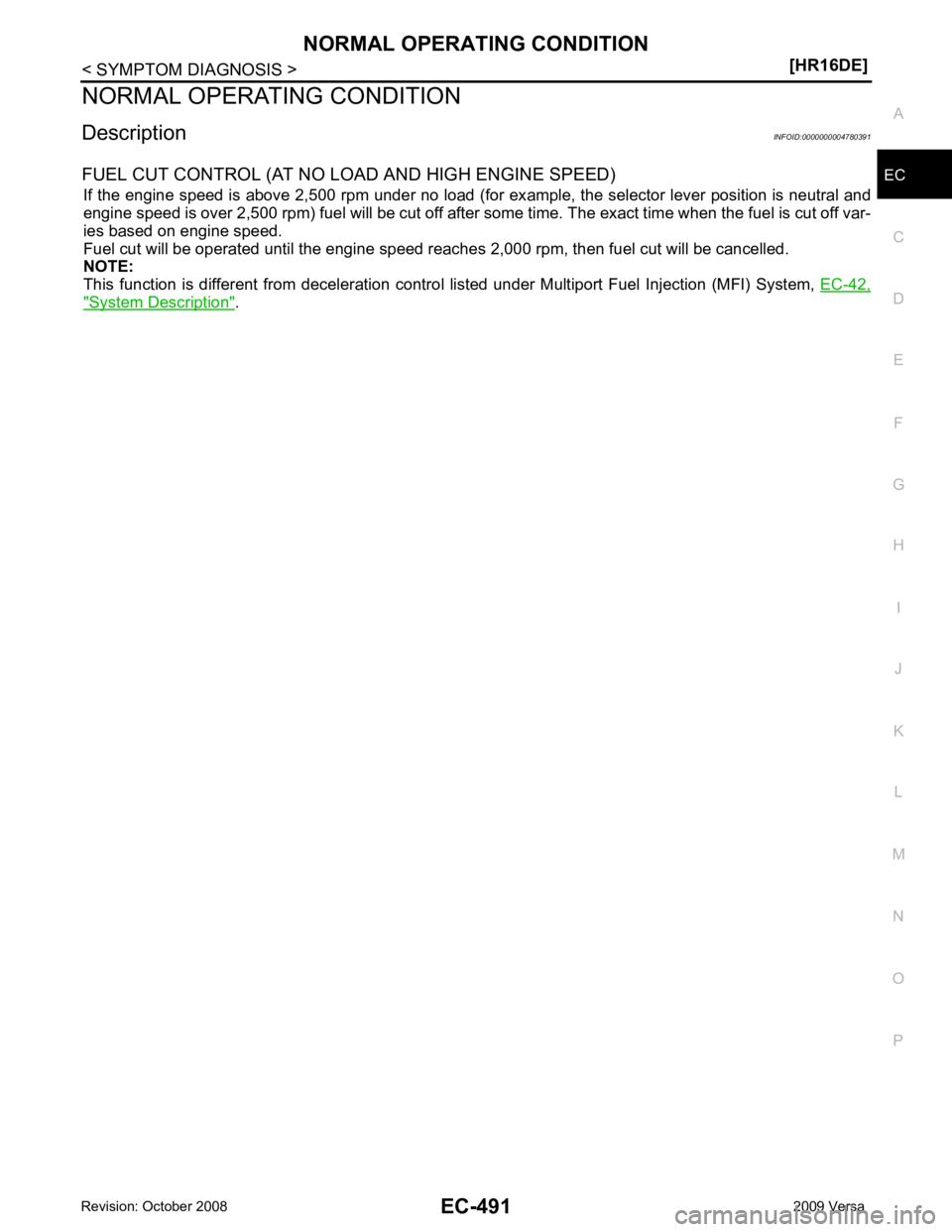
NORMAL OPERATING CONDITION
Description INFOID:0000000004780391
FUEL CUT CONTROL (AT NO LOAD AND HIGH ENGINE SPEED) If the engine speed is above 2,500 rpm under no load (for ex ample, the selector lever position is neutral and
engine speed is over 2,500 rpm) fuel will be cut off after some time. The exact time when the fuel is cut off var-
ies based on engine speed.
Fuel cut will be operated until the engine speed reaches 2,000 rpm, then fuel cut will be cancelled.
NOTE:
This function is different from deceleration contro l listed under Multiport Fuel Injection (MFI) System, EC-42," System Description " .
Page 1849 of 4331
![NISSAN TIIDA 2009 Service Repair Manual PRECAUTIONS
EC-493
< PRECAUTION >
[HR16DE] C
D E
F
G H
I
J
K L
M A EC
NP
O
• Be sure to route and secure the harnesses properly
after work. The interference of the harness with
a bracket, etc. may NISSAN TIIDA 2009 Service Repair Manual PRECAUTIONS
EC-493
< PRECAUTION >
[HR16DE] C
D E
F
G H
I
J
K L
M A EC
NP
O
• Be sure to route and secure the harnesses properly
after work. The interference of the harness with
a bracket, etc. may](/manual-img/5/57398/w960_57398-1848.png)
PRECAUTIONS
EC-493
< PRECAUTION >
[HR16DE] C
D E
F
G H
I
J
K L
M A EC
NP
O
• Be sure to route and secure the harnesses properly
after work. The interference of the harness with
a bracket, etc. may cause the MIL to li ght up due to the short circuit.
• Be sure to connect rubber tubes properly afte r work. A misconnected or disconnected rubber tube
may cause the MIL to light up due to the malfuncti on of the EVAP system or fuel injection system,
etc.
• Be sure to erase the unnecessary malfunction informa tion (repairs completed) from the ECM and
TCM (Transmission control module) before returning the vehicle to the customer.
General Precautions INFOID:0000000004780395
• Always use a 12 volt battery as power source.
• Do not attempt to disconnect battery cables while engine is
running.
• Before connecting or disc onnecting the ECM harness con-
nector, turn ignition switch OFF and disconnect negative bat-
tery cable. Failure to do so may damage the ECM because
battery voltage is applied to ECM even if ignition switch is
turned OFF.
• Before removing parts, turn ig nition switch OFF and then dis-
connect negative battery cable.
• Do not disassemble ECM.
• If a battery cable is disconnect ed, the memory will return to
the ECM value.
The ECM will now start to self-control at its initial value. Thus,
engine operation can vary slight ly in this case. However, this
is not an indication of a malf unction. Do not replace parts
because of a slight variation.
• If the battery is disconnected, the following emission-related
diagnostic information will be cleared within 24 hours.
- Diagnostic trouble codes
- 1st trip diagnostic trouble codes
- Freeze frame data
- 1st trip freeze frame data
- System readiness test (SRT) codes
- Test values
• When connecting ECM harness c onnector (1), fasten (B) it
securely with a lever as far as it will go as shown in the figure.
• When connecting or disconnect ing pin connectors into or
from ECM, take care not to damage pin terminals (bend or
break).
Make sure that there are not any bends or breaks on ECM pin
terminal, when connecting pin connectors.
• Securely connect ECM harness connectors.
A poor connection can cause an extremely high (surge) volt-
age to develop in coil and cond enser, thus resulting in dam-
age to ICs.
• Keep engine control system harness at least 10 cm (4 in) away
from adjacent harness, to prevent engine control system mal- SEF289H
2. ECM
A. Loosen PBIA9222J
PBIB2947E
PBIB0090E
Page 1851 of 4331
EC
NP
O
•
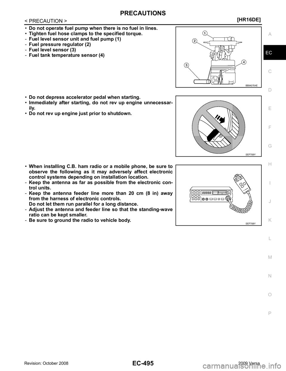
Do not operate fuel pump when there is no fuel in lines.
• Tighten fuel hose clamps to the specified torque.
- Fuel level sensor unit and fuel pump (1)
- Fuel pressure regulator (2)
- Fuel level sensor (3)
- Fuel tank temperature sensor (4)
• Do not depress accelerator pedal when starting.
• Immediately after starting, do not rev up engine unnecessar-
ily.
• Do not rev up engine ju st prior to shutdown.
• When installing C.B. ham radio or a mobile phone, be sure to
observe the following as it may adversely affect electronic
control systems depending on installation location.
- Keep the antenna as far as possible from the electronic con-
trol units.
- Keep the antenna feeder line more than 20 cm (8 in) away
from the harness of electronic controls.
Do not let them run para llel for a long distance.
- Adjust the antenna and feeder line so that the standing-wave
ratio can be kept smaller.
- Be sure to ground the radio to vehicle body.
Page 1869 of 4331
![NISSAN TIIDA 2009 Service Repair Manual PRECAUTIONS
EC-513
< SERVICE INFOMATION >
[MR TYPE 1] C
D E
F
G H
I
J
K L
M A EC
NP
O
• Be sure to connect rubber tubes properly afte
r work. A misconnected or disconnected rubber tube NISSAN TIIDA 2009 Service Repair Manual PRECAUTIONS
EC-513
< SERVICE INFOMATION >
[MR TYPE 1] C
D E
F
G H
I
J
K L
M A EC
NP
O
• Be sure to connect rubber tubes properly afte
r work. A misconnected or disconnected rubber tube](/manual-img/5/57398/w960_57398-1868.png)
PRECAUTIONS
EC-513
< SERVICE INFOMATION >
[MR TYPE 1] C
D E
F
G H
I
J
K L
M A EC
NP
O
• Be sure to connect rubber tubes properly afte
r work. A misconnected or disconnected rubber tube
may cause the MIL to light up due to the malfunction of the fuel injection system, etc.
• Be sure to erase the unnecessary malfunction informa tion (repairs completed) from the ECM and
TCM (Transmission control module) before returning the vehicle to the customer.
Precaution INFOID:0000000004537016
• Always use a 12 volt battery as power source.
• Do not attempt to disconnect battery cables while engine is
running.
• Before connecting or disc onnecting the ECM harness con-
nector, turn ignition switch OFF and disconnect negative bat-
tery cable. Failure to do so may damage the ECM because
battery voltage is applied to ECM even if ignition switch is
turned OFF.
• Before removing parts, turn ig nition switch OFF and then dis-
connect negative battery cable.
• Do not disassemble ECM.
• If battery cable is disconnected, the memory will return to the
initial ECM values.
The ECM will now start to self-c ontrol at its initial values.
Engine operation can vary slight ly in this case. However, this
is not an indication of a malf unction. Do not replace parts
because of a slight variation.
• If the battery is disconnected, the following emission-related
diagnostic information will be lost within 24 hours.
- Diagnostic trouble codes
- 1st trip diagnostic trouble codes
- Freeze frame data
- 1st trip freeze frame data
- System readiness test (SRT) codes
- Test values
• When connecting ECM harness connector, fasten (B) it
securely with a lever (1) as far as it will go as shown in the fig-
ure.
- ECM (2)
- Loosen (A)
• When connecting or disconnect ing pin connectors into or
from ECM, take care not to damage pin terminals (bend or
break).
Make sure that there are not any bends or breaks on ECM pin
terminal, when connecting pin connectors.
• Securely connect ECM harness connectors.
A poor connection can cause an extremely high (surge) volt-
age to develop in coil and cond enser, thus resulting in dam-
age to ICs.
• Keep engine control system harness at least 10 cm (4 in) away
from adjacent harness, to prevent engine control system mal-
functions due to receiving externa l noise, degraded operation
of ICs, etc. SEF289H
PBIA9222J
PBIB2947E
PBIB0090E
Page 1870 of 4331
![NISSAN TIIDA 2009 Service Repair Manual EC-514< SERVICE INFOMATION >
[MR TYPE 1]
PRECAUTIONS
• Keep engine control system parts and harness dry.
• Before replacing ECM, perform “ECM Terminals and Refer-
ence Value” inspecti NISSAN TIIDA 2009 Service Repair Manual EC-514< SERVICE INFOMATION >
[MR TYPE 1]
PRECAUTIONS
• Keep engine control system parts and harness dry.
• Before replacing ECM, perform “ECM Terminals and Refer-
ence Value” inspecti](/manual-img/5/57398/w960_57398-1869.png)
EC-514< SERVICE INFOMATION >
[MR TYPE 1]
PRECAUTIONS
• Keep engine control system parts and harness dry.
• Before replacing ECM, perform “ECM Terminals and Refer-
ence Value” inspection and m ake sure ECM functions prop-
erly. Refer to EC-597, " ECM Terminal and Reference Value " .
• Handle mass air flow sensor carefully to avoid damage.
• Do not disassemble m ass air flow sensor.
• Do not clean mass air flow senso r with any type of detergent.
• Do not disassemble electric throttle control actuator.
• Even a slight leak in the ai r intake system can cause serious
incidents.
• Do not shock or jar the camshaft position sensor (PHASE),
crankshaft position sensor (POS).
• After performing each TROUBLE DIAGNOSIS, perform DTC
Confirmation Procedure or Overall Function Check.
The DTC should not be displ ayed in the DTC Confirmation
Procedure if the repair is co mpleted. The Overall Function
Check should be a good result if the repair is completed.
• When measuring ECM signals with a circuit tester, never allow
the two tester probes to contact.
Accidental contact of probes will cause a short circuit and
damage the ECM power transistor.
• Do not use ECM ground termina ls when measuring input/out-
put voltage. Doing so may result in damage to the ECM's tran-
sistor. Use a ground other than ECM terminals, such as the
ground. MEF040D
SEF217U
SEF348N