2009 NISSAN TIIDA engine control system
[x] Cancel search: engine control systemPage 1871 of 4331
![NISSAN TIIDA 2009 Service Repair Manual PRECAUTIONS
EC-515
< SERVICE INFOMATION >
[MR TYPE 1] C
D E
F
G H
I
J
K L
M A EC
NP
O
•
Do not operate fuel pump when there is no fuel in lines.
• Tighten fuel hose clamps to the specified torqu NISSAN TIIDA 2009 Service Repair Manual PRECAUTIONS
EC-515
< SERVICE INFOMATION >
[MR TYPE 1] C
D E
F
G H
I
J
K L
M A EC
NP
O
•
Do not operate fuel pump when there is no fuel in lines.
• Tighten fuel hose clamps to the specified torqu](/manual-img/5/57398/w960_57398-1870.png)
PRECAUTIONS
EC-515
< SERVICE INFOMATION >
[MR TYPE 1] C
D E
F
G H
I
J
K L
M A EC
NP
O
•
Do not operate fuel pump when there is no fuel in lines.
• Tighten fuel hose clamps to the specified torque.
- Fuel level sensor unit and fuel pump (1)
- Fuel pressure regulator (2)
- Fuel level sensor (3)
- Fuel tank temperature sensor (4)
• Do not depress accelerator pedal when starting.
• Immediately after starting, do not rev up engine unnecessar-
ily.
• Do not rev up engine ju st prior to shutdown.
• When installing C.B. ham radio or a mobile phone, be sure to
observe the following as it may adversely affect electronic
control systems depending on installation location.
- Keep the antenna as far as possible from the electronic con-
trol units.
- Keep the antenna feeder line more than 20 cm (8 in) away
from the harness of electronic controls.
Do not let them run para llel for a long distance.
- Adjust the antenna and feeder line so that the standing-wave
radio can be kept smaller.
- Be sure to ground the radio to vehicle body. BBIA0704E
SEF709Y
SEF708Y
Page 1875 of 4331

EC
NP
O
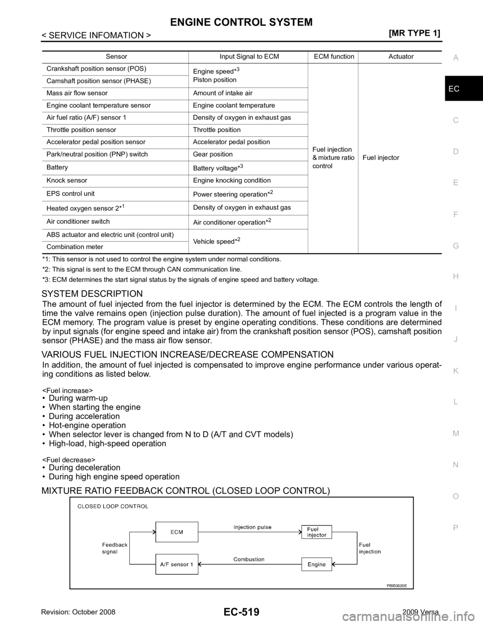
*1: This sensor is not used to control the engine system under normal conditions.
*2: This signal is sent to the ECM through CAN communication line.
*3: ECM determines the start signal status by the signals of engine speed and battery voltage.
SYSTEM DESCRIPTION The amount of fuel injected from the fuel injector is determined by the ECM. The ECM controls the length of
time the valve remains open (injection pulse duration). T he amount of fuel injected is a program value in the
ECM memory. The program value is preset by engi ne operating conditions. These conditions are determined
by input signals (for engine speed and intake air) from t he crankshaft position sensor (POS), camshaft position
sensor (PHASE) and the mass air flow sensor.
VARIOUS FUEL INJECTION INCREASE/DECREASE COMPENSATION In addition, the amount of fuel injected is compens ated to improve engine performance under various operat-
ing conditions as listed below.
• During warm-up
• When starting the engine
• During acceleration
• Hot-engine operation
• When selector lever is changed from N to D (A/T and CVT models)
• High-load, high-speed operation
• During deceleration
• During high engine speed operation
MIXTURE RATIO FEEDBACK CONTROL (CLOSED LOOP CONTROL) Sensor Input Signal to ECM ECM function Actuator
Crankshaft position sensor (POS) Engine speed*3
Piston position
Fuel injection
& mixture ratio
control Fuel injector
Camshaft position sensor (PHASE)
Mass air flow sensor Amount of intake air
Engine coolant temperature sensor Engine coolant temperature
Air fuel ratio (A/F) sensor 1 Density of oxygen in exhaust gas
Throttle position sensor Throttle position
Accelerator pedal position sensor Accelerator pedal position
Park/neutral position (PNP) switch Gear position
Battery Battery voltage*3
Knock sensor Engine knocking condition
EPS control unit Power steering operation*2
Heated oxygen sensor 2* 1
Density of oxygen in exhaust gas
Air conditioner switch Air conditioner operation*2
ABS actuator and electric unit (control unit) Vehicle speed*2
Combination meter
Page 1876 of 4331
![NISSAN TIIDA 2009 Service Repair Manual EC-520< SERVICE INFOMATION >
[MR TYPE 1]
ENGINE CONTROL SYSTEM
The mixture ratio feedback system provides the best air/ fuel mixture ratio for driveability and emission control.
The three way catal NISSAN TIIDA 2009 Service Repair Manual EC-520< SERVICE INFOMATION >
[MR TYPE 1]
ENGINE CONTROL SYSTEM
The mixture ratio feedback system provides the best air/ fuel mixture ratio for driveability and emission control.
The three way catal](/manual-img/5/57398/w960_57398-1875.png)
EC-520< SERVICE INFOMATION >
[MR TYPE 1]
ENGINE CONTROL SYSTEM
The mixture ratio feedback system provides the best air/ fuel mixture ratio for driveability and emission control.
The three way catalyst (manifold) can then better r educe CO, HC and NOx emissions. This system uses air
fuel ratio (A/F) sensor 1 in the exhaust manifold to monitor whether the engine operation is rich or lean. The
ECM adjusts the injection pulse width according to t he sensor voltage signal. For more information about air
fuel ratio (A/F) sensor 1, refer to EC-698 . This maintains the mixture ratio within the range of stoichiometric
(ideal air/fuel mixture).
This stage is referred to as the closed loop control condition.
Heated oxygen sensor 2 is located downstream of the th ree way catalyst (manifold). Even if the switching
characteristics of air fuel ratio (A/F) sensor 1 shift, the air/fuel ratio is controlled to stoichiometric by the signal
from heated oxygen sensor 2.
Open Loop Control
The open loop system condition refers to when the EC M detects any of the following conditions. Feedback
control stops in order to maintain stabilized fuel combustion.
• Deceleration and acceleration
• High-load, high-speed operation
• Malfunction of air fuel ratio (A/F) sensor 1 or its circuit
• Insufficient activation of air fuel ratio (A /F) sensor 1 at low engine coolant temperature
• High engine coolant temperature
• During warm-up
• After shifting from N to D (A/T and CVT models)
• When starting the engine
MIXTURE RATIO SELF-LEARNING CONTROL
The mixture ratio feedback control system monitors the mixt ure ratio signal transmitted from air fuel ratio (A/F)
sensor 1. This feedback signal is then sent to the ECM. The ECM controls the basic mixture ratio as close to
the theoretical mixture ratio as possible. However, the bas ic mixture ratio is not necessarily controlled as orig-
inally designed. Both manufacturing differences (i.e., mass air flow sensor hot wire) and characteristic
changes during operation (i.e., fuel injector clogging) directly affect mixture ratio.
Accordingly, the difference between the basic and theoretical mixture ratios is monitored in this system. This is
then computed in terms of “injection pulse duration” to automatically compensate for the difference between
the two ratios.
“Fuel trim” refers to the feedback compensation value co mpared against the basic injection duration. Fuel trim
includes short term fuel trim and long term fuel trim.
“Short term fuel trim” is the short-term fuel compensati on used to maintain the mixture ratio at its theoretical
value. The signal from air fuel ratio (A/F) sensor 1 i ndicates whether the mixture ratio is RICH or LEAN com-
pared to the theoretical value. The signal then triggers a r eduction in fuel volume if the mixture ratio is rich, and
an increase in fuel volume if it is lean.
“Long term fuel trim” is overall fuel compensation carri ed out long-term to compensate for continual deviation
of the short term fuel trim from t he central value. Such deviation will occur due to individual engine differences,
wear over time and changes in the usage environment.
FUEL INJECTION TIMING
Two types of systems are used.
Sequential Multiport Fuel Injection System
Fuel is injected into each cylinder during each engine cycl e according to the firing order. This system is used
when the engine is running.
Simultaneous Multiport Fuel Injection System
Fuel is injected simultaneously into all four cylinders twice each engine cycle. In other words, pulse signals of
the same width are simultaneously transmitted from the ECM.
The four fuel injectors will then receive the signals two times for each engine cycle. SEF337W
Page 1877 of 4331

EC
NP
O
This system is used when the engine is being started
and/or if the fail-safe system (CPU) is operating.
FUEL SHUT-OFF Fuel to each cylinder is cut off during deceleration, operation of the engine at excessively high speeds or oper-
ation of the vehicle at excessively high speeds.
Electronic Ignition (EI) System INFOID:0000000004537021
INPUT/OUTPUT SIGNAL CHART
*1: This signal is sent to the ECM through CAN communication line.
*2: ECM determines the start signal status by the signals of engine speed and battery voltage.
SYSTEM DESCRIPTION Firing order: 1 - 3 - 4 - 2
The ignition timing is controlled by the ECM to maintain the best air-fuel ratio for every running condition of the
engine. The ignition timing data is stored in the ECM.
The ECM receives information such as the injecti on pulse width and camshaft position sensor (PHASE) sig-
nal. Computing this information, ignition si gnals are transmitted to the power transistor.
During the following conditions, the ignition timing is revi sed by the ECM according to the other data stored in
the ECM.
• At starting
• During warm-up
• At idle
• At low battery voltage
• During acceleration
The knock sensor retard system is designed only for emergencies. The basic ignition timing is programmed
within the anti-knocking zone, if recommended fuel is used under dry conditions. The retard system does not
operate under normal driving conditions. If engine knocking occurs, the knock sensor monitors the condition.
The signal is transmitted to the ECM. The ECM retards the ignition timing to eliminate the knocking condition.
Fuel Cut Control (at No Load and High Engine Speed) INFOID:0000000004537022
INPUT/OUTPUT SIGNAL CHART Sensor Input Signal to ECM ECM function Actuator
Crankshaft position sensor (POS) Engine speed*2
Piston position
Ignition timing
control Power transistor
Camshaft position sensor (PHASE)
Mass air flow sensor Amount of intake air
Engine coolant temperature sensor Engine coolant temperature
Throttle position sensor Throttle position
Accelerator pedal position sensor Accelerator pedal position
Battery Battery voltage*2
Knock sensor Engine knocking
Park/neutral position (PNP) switch Gear position
ABS actuator and electric unit (control unit) Vehicle speed*1
Combination meter Sensor Input Signal to ECM ECM function Actuator
Park/neutral position (PNP) switch Neutral position
Fuel cut control Fuel injector
Accelerator pedal position sensor Accelerator pedal position
Engine coolant temperature sensor Engine coolant temperature
Crankshaft position sensor (POS)
Camshaft position sensor (PHASE) Engine speed
ABS actuator and electric unit (control unit) Vehicle speed*
Combination meter
Page 1879 of 4331

EC
NP
O
AIR CONDITIONING
CUT CONTROL
Input/Output Signal Chart INFOID:0000000004537023
*1: This signal is sent to the ECM through CAN communication line.
*2: ECM determines the start signal status by the signals of engine speed and battery voltage.
System Description INFOID:0000000004537024
This system improves engine operation when the air conditioner is used.
Under the following conditions, the air conditioner is turned off.
• When the accelerator pedal is fully depressed.
• When cranking the engine.
• At high engine speeds.
• When the engine coolant temperature becomes excessively high.
• When operating power steering during low engine speed or low vehicle speed.
• When engine speed is excessively low.
• When refrigerant pressure is excessively low or high. Sensor Input Signal to ECM ECM function Actuator
Air conditioner switch Air conditioner ON signal*1
Air conditioner
cut control Air conditioner relay
Accelerator pedal position sensor Accelerator pedal position
Crankshaft position sensor (POS)
Camshaft position sensor (PHASE) Engine speed*
2
Engine coolant temperature sensor Engine coolant temperature
Battery Battery voltage*2
Refrigerant pressure sensor Refrigerant pressure
EPS control unit Power steering operation*1
ABS actuator and electric unit (control unit) Vehicle speed*1
Combination meter
Page 1883 of 4331

EC
NP
O
EVAPORATIVE EMISSION SYSTEM
Description INFOID:0000000004537028
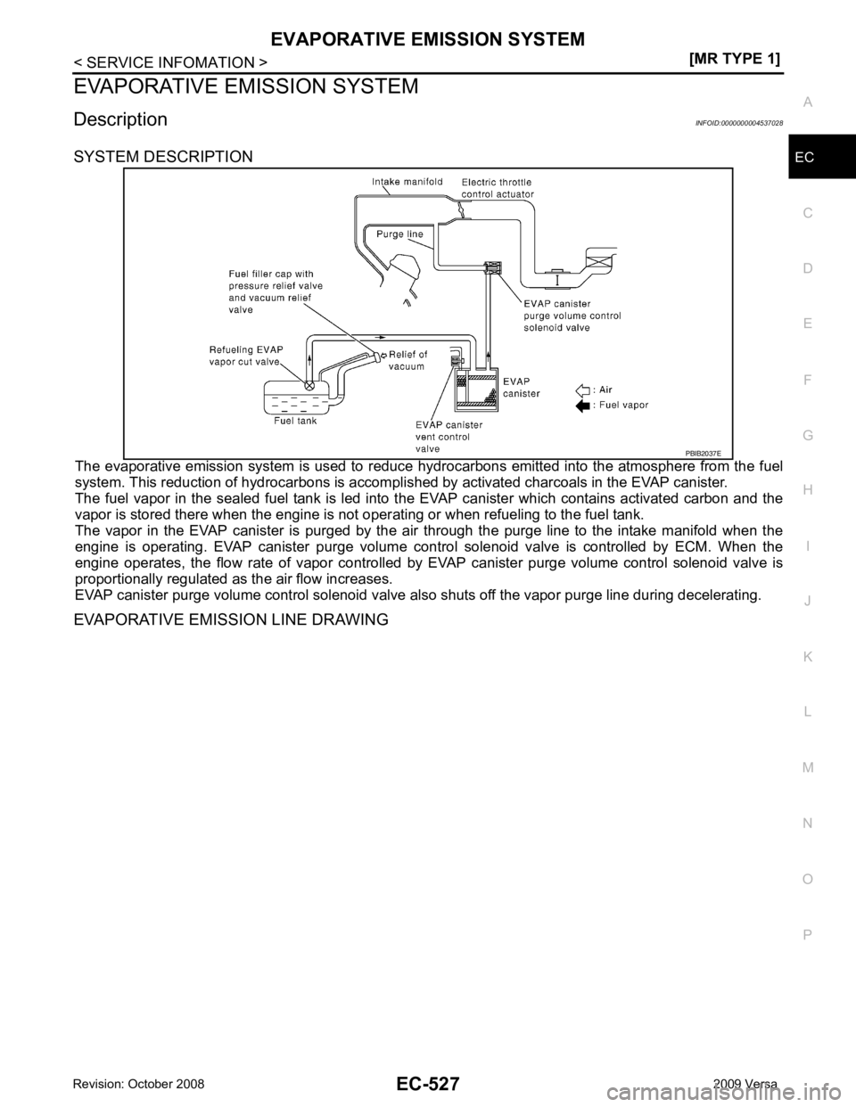
SYSTEM DESCRIPTION
The evaporative emission system is used to reduce hydr ocarbons emitted into the atmosphere from the fuel
system. This reduction of hydrocarbons is accompli shed by activated charcoals in the EVAP canister.
The fuel vapor in the sealed fuel tank is led into t he EVAP canister which contains activated carbon and the
vapor is stored there when the engine is not oper ating or when refueling to the fuel tank.
The vapor in the EVAP canister is purged by the air through the purge line to the intake manifold when the
engine is operating. EVAP canister purge volume control solenoid valve is controlled by ECM. When the
engine operates, the flow rate of vapor controlled by EVAP canister purge volume control solenoid valve is
proportionally regulated as the air flow increases.
EVAP canister purge volume control solenoid valve al so shuts off the vapor purge line during decelerating.
EVAPORATIVE EMISSION LINE DRAWING
Page 1887 of 4331
![NISSAN TIIDA 2009 Service Repair Manual EVAPORATIVE EMISSION SYSTEM
EC-531
< SERVICE INFOMATION >
[MR TYPE 1] C
D E
F
G H
I
J
K L
M A EC
NP
O
Positive pressure is delivered to the EVAP system through the EVAP
service port. If fuel vapor lea NISSAN TIIDA 2009 Service Repair Manual EVAPORATIVE EMISSION SYSTEM
EC-531
< SERVICE INFOMATION >
[MR TYPE 1] C
D E
F
G H
I
J
K L
M A EC
NP
O
Positive pressure is delivered to the EVAP system through the EVAP
service port. If fuel vapor lea](/manual-img/5/57398/w960_57398-1886.png)
EVAPORATIVE EMISSION SYSTEM
EC-531
< SERVICE INFOMATION >
[MR TYPE 1] C
D E
F
G H
I
J
K L
M A EC
NP
O
Positive pressure is delivered to the EVAP system through the EVAP
service port. If fuel vapor leakage in the EVAP system occurs, use a
leak detector to locate the leak.
Removal and Installation INFOID:0000000004537030
EVAP CANISTER Tighten EVAP canister as shown in the figure.
EVAP CANISTER VENT CONTROL VALVE 1. Turn EVAP canister vent control valve counterclockwise.
• Lock (A)
• Unlock (B)
2. Remove the EVAP canister vent control valve.
Always replace O-ring with a new one.
How to Detect Fuel Vapor Leakage INFOID:0000000004537031
CAUTION:
• Never use compressed air or a high pressure pump.
• Do not exceed 4.12 kPa (0.042 kg/cm 2
, 0.6 psi) of pressure in EVAP system.
NOTE:
• Do not start engine.
• Improper installation of EVAP service port adapter to the EVAP service port may cause a leak.
WITH CONSULT-III
1. Attach the EVAP service port adapter securely to the EVAP service port.
2. Also attach the pressure pump and hose to the EVAP service port adapter. SEF462UC
PBIB1214E
PBIB3091E
Page 1897 of 4331

EC
NP
O
ON BOARD DIAGNOSTIC (OBD) SYSTEM
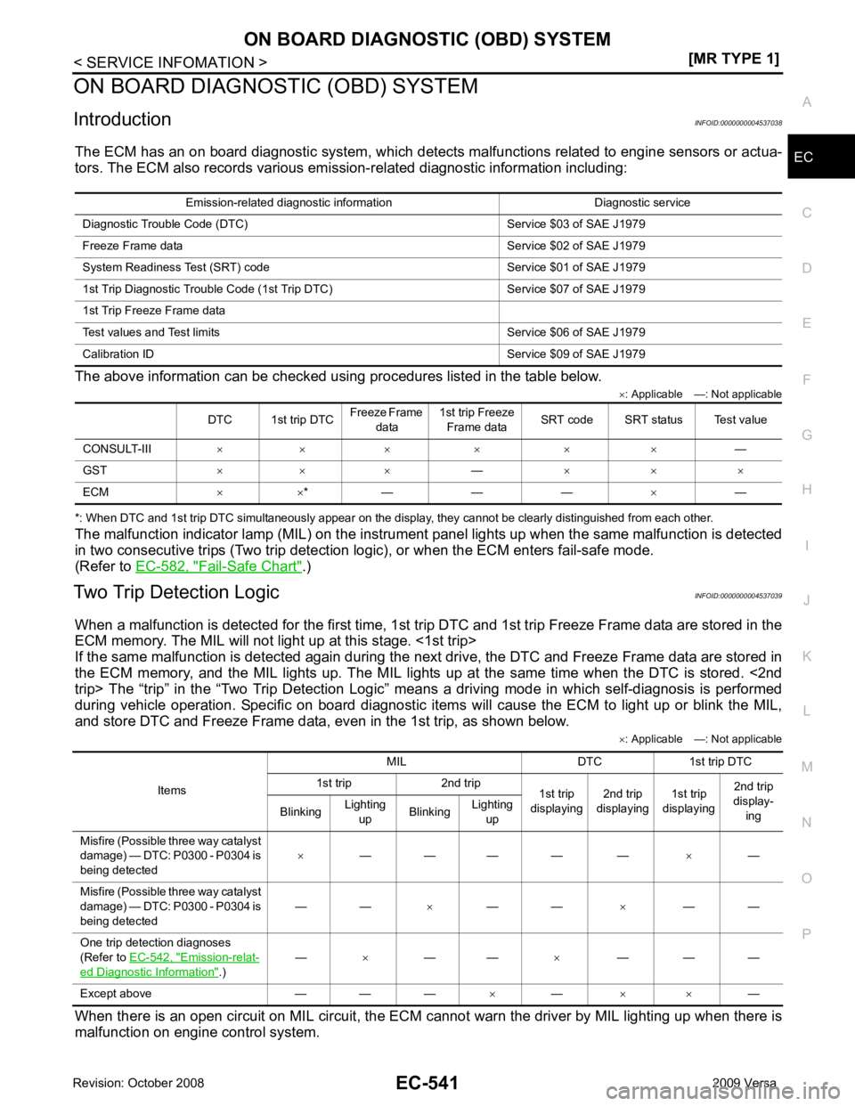
Introduction INFOID:0000000004537038
The ECM has an on board diagnostic system, which detects malfunctions related to engine sensors or actua-
tors. The ECM also records various emis sion-related diagnostic information including:
The above information can be checked using procedures listed in the table below. ×: Applicable —: Not applicable
*: When DTC and 1st trip DTC simultaneously appear on the display, they cannot be clearly distinguished from each other.
The malfunction indicator lamp (MIL) on the instrument panel lights up when the same malfunction is detected
in two consecutive trips (Two trip detection logic), or when the ECM enters fail-safe mode.
(Refer to EC-582, " Fail-Safe Chart " .)
Two Trip Detection Logic INFOID:0000000004537039
When a malfunction is detected for the first time, 1st tr ip DTC and 1st trip Freeze Frame data are stored in the
ECM memory. The MIL will not light up at this stage. <1st trip>
If the same malfunction is detected again during the next drive, the DTC and Freeze Frame data are stored in
the ECM memory, and the MIL lights up. The MIL lights up at the same time when the DTC is stored. <2nd
trip> The “trip” in the “Two Trip Detection Logic” m eans a driving mode in which self-diagnosis is performed
during vehicle operation. Specific on board diagnostic item s will cause the ECM to light up or blink the MIL,
and store DTC and Freeze Frame data, even in the 1st trip, as shown below.
×: Applicable —: Not applicable
When there is an open circuit on MIL circuit, the ECM c annot warn the driver by MIL lighting up when there is
malfunction on engine control system. Emission-related diagnostic information Diagnostic service
Diagnostic Tr ouble Code (DTC) Service $03 of SAE J1979
Freeze Frame data Service $02 of SAE J1979
System Readiness Test (SRT) code Service $01 of SAE J1979
1st Trip Diagnostic Trou ble Code (1st Trip DTC) Service $07 of SAE J1979
1st Trip Freeze Frame data
Test values and Test limi ts Service $06 of SAE J1979
Calibration ID Servic e $09 of SAE J1979
DTC 1st trip DTC Freeze Frame
data 1st trip Freeze
Frame data SRT code SRT status Test value
CONSULT-III × × × × × × —
GST × × × —× × ×
ECM × ×* — — — ×— Items
MIL DTC 1st trip DTC
1st trip 2nd trip 1st trip
displaying 2nd trip
displaying 1st trip
displaying 2nd trip
display-
ing
Blinking Lighting
up Blinking
Lighting
up
Misfire (Possible three way catalyst
damage) — DTC: P0300 - P0304 is
being detected ×
— — — — — ×—
Misfire (Possible three way catalyst
damage) — DTC: P0300 - P0304 is
being detected — —
×— — ×— —
One trip detection diagnoses
(Refer to EC-542, " Emission-relat-
ed Diagnostic Information " .)
—
×— — ×— — —
Except above — — — ×— × × —