2009 NISSAN LATIO check engine
[x] Cancel search: check enginePage 3964 of 4331
MTC
N
O P
1. Use the recovery/recycling equipment
to evacuate the refrigerant. Refer to MTC-74, " HFC-134a (R-134a)
Service Procedure " .
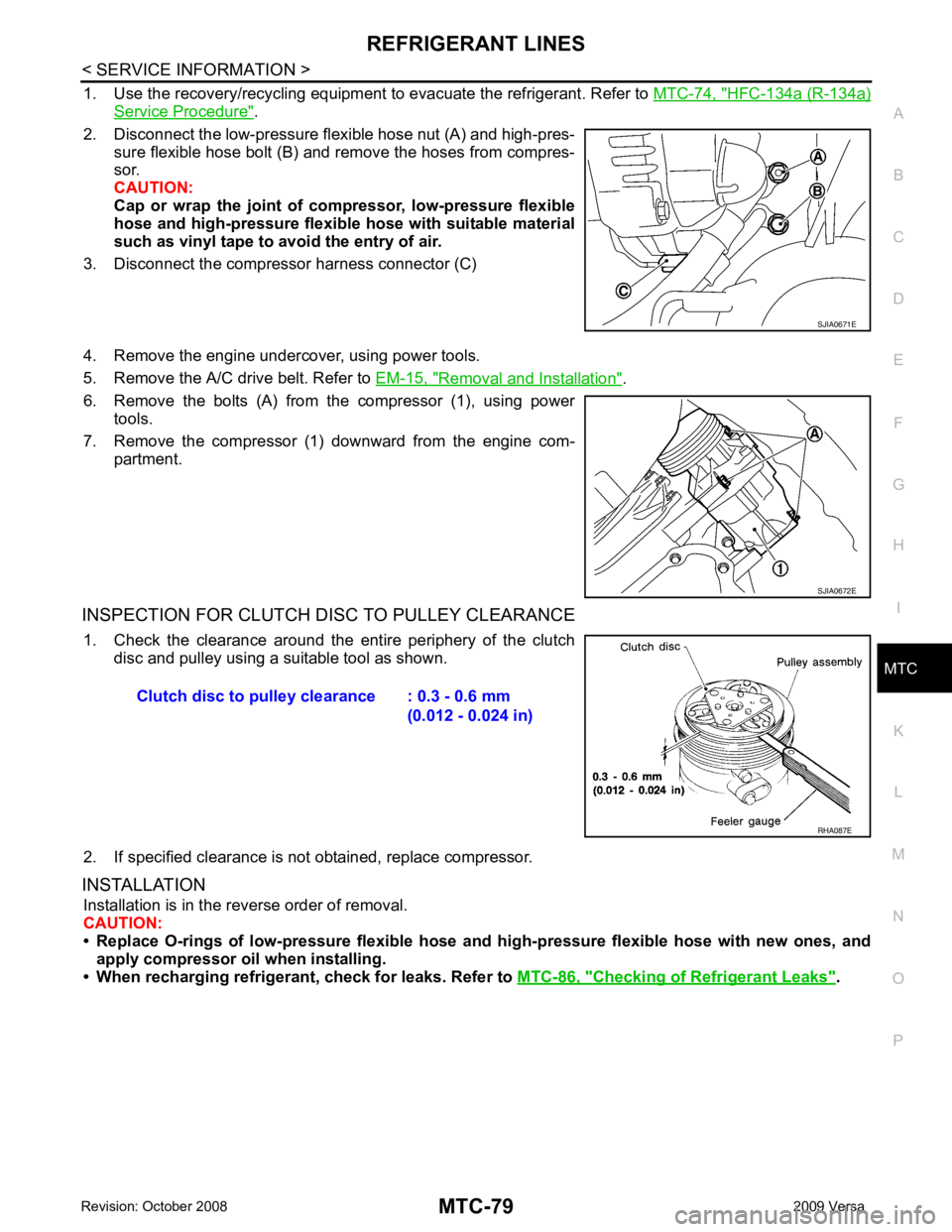
2. Disconnect the low-pressure flexible hose nut (A) and high-pres- sure flexible hose bolt (B) and remove the hoses from compres-
sor.
CAUTION:
Cap or wrap the joint of co mpressor, low-pressure flexible
hose and high-pressure flexible hose with suitable material
such as vinyl tape to avoid the entry of air.
3. Disconnect the compressor harness connector (C)
4. Remove the engine undercover, using power tools.
5. Remove the A/C drive belt. Refer to EM-15, " Removal and Installation " .
6. Remove the bolts (A) from the compressor (1), using power tools.
7. Remove the compressor (1) downward from the engine com- partment.
INSPECTION FOR CLUTCH DISC TO PULLEY CLEARANCE 1. Check the clearance around the entire periphery of the clutch disc and pulley using a suitable tool as shown.
2. If specified clearance is not obtained, replace compressor.
INSTALLATION Installation is in the reverse order of removal.
CAUTION:
• Replace O-rings of low-pressure flexible hose and high-pressure flexible hose with new ones, and
apply compressor oil when installing.
• When recharging refrigeran t, check for leaks. Refer to MTC-86, " Checking of Refrigerant Leaks " .
Page 3966 of 4331
MTC
N
O P
INSPECTION FOR CLUTCH DISC TO PULLEY CLEARANCE
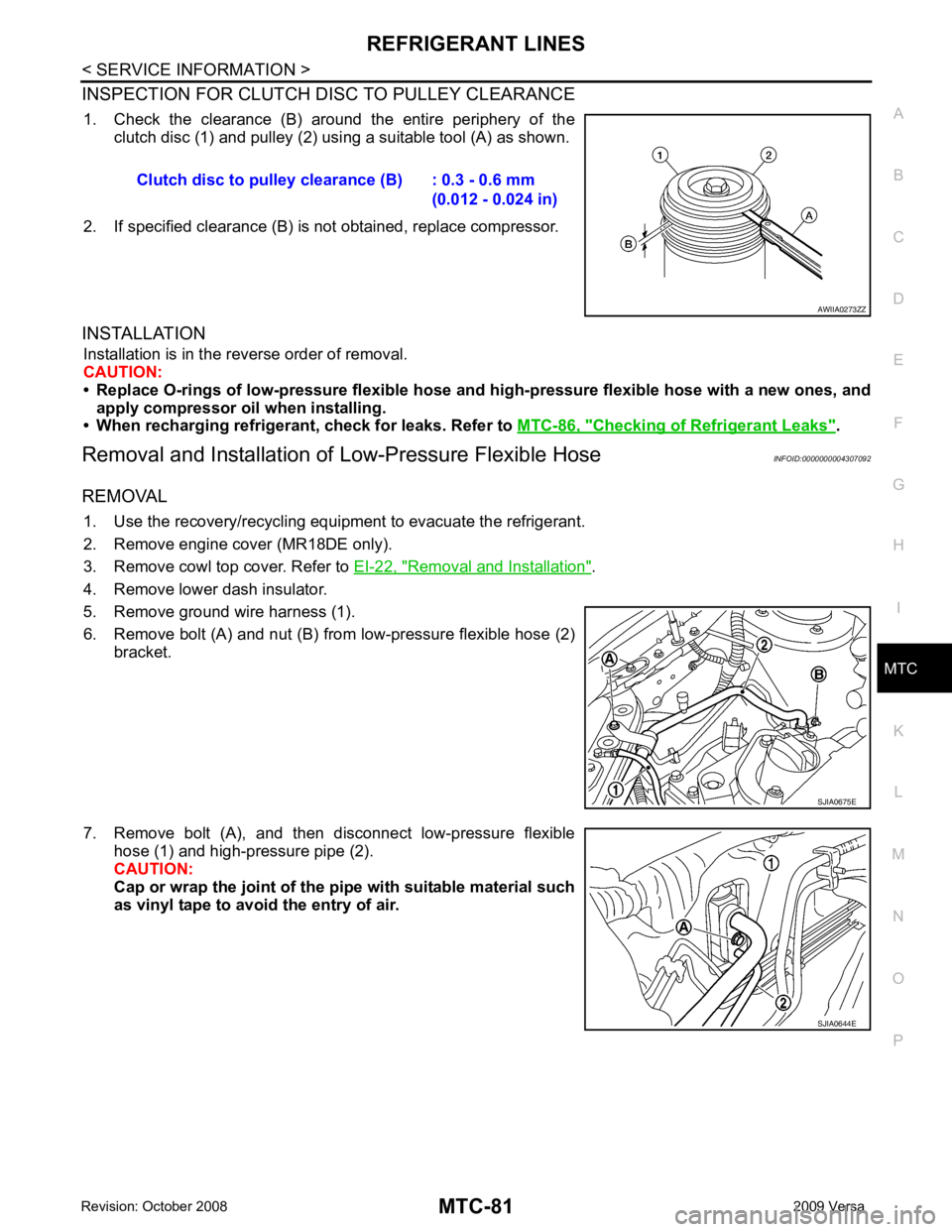
1. Check the clearance (B) around the entire periphery of the clutch disc (1) and pulley (2) usi ng a suitable tool (A) as shown.
2. If specified clearance (B) is not obtained, replace compressor.
INSTALLATION Installation is in the reverse order of removal.
CAUTION:
• Replace O-rings of low-pressure flexible hose and high-pressure flexible hose with a new ones, and
apply compressor oil when installing.
• When recharging refrigeran t, check for leaks. Refer to MTC-86, " Checking of Refrigerant Leaks " .
Removal and Installation of Low-Pressure Flexible Hose INFOID:0000000004307092
REMOVAL 1. Use the recovery/recycling equipment to evacuate the refrigerant.
2. Remove engine cover (MR18DE only).
3. Remove cowl top cover. Refer to EI-22, " Removal and Installation " .
4. Remove lower dash insulator.
5. Remove ground wire harness (1).
6. Remove bolt (A) and nut (B) from low-pressure flexible hose (2) bracket.
7. Remove bolt (A), and then disconnect low-pressure flexible hose (1) and high-pressure pipe (2).
CAUTION:
Cap or wrap the joint of the pi pe with suitable material such
as vinyl tape to avoid the entry of air. Clutch disc to pulley clearance (B) : 0.3 - 0.6 mm
(0.012 - 0.024 in)
Page 3972 of 4331
REFRIGERANT LINES
MTC-87
< SERVICE INFORMATION >
C
D E
F
G H
I
K L
M A
B MTC
N
O P
Moving the electronic leak detector probe slower
and closer to the suspected leak area will improve
the chances of finding a leak.
Checking System for Leaks Using the Fluorescent Leak Detector INFOID:0000000004307101
1. Check A/C system for leaks using the UV lamp and safety goggles J-42220 in a low sunlight area (area
without windows preferable). Illuminate all components, fittings and lines. The dye will appear as a bright
green/yellow area at the point of leakage. Fluoresc ent dye observed at the evaporator drain opening indi-
cates an evaporator core assembly (tubes , core or expansion valve) leak.
2. If the suspected area is difficult to see, use an adjustable mirror or wipe the area with a clean shop rag or
cloth, with the UV lamp for dye residue.
3. After the leak is repaired, remove any residual dye using dye cleaner J-43872 to prevent future misdiag- nosis.
4. Perform a system performance check and verify the leak repair with an approved electronic refrigerant leak detector.
NOTE:
Other gases in the work area or substances on the A/C components, for example, anti-freeze, windshield
washer fluid, solvents and oils, may falsely trigger the l eak detector. Make sure the surfaces to be checked are
clean.
Clean with a dry cloth or blow off with shop air.
Do not allow the sensor tip of the detector to contact with any substance. This can also cause false readings
and may damage the detector.
Dye Injection INFOID:0000000004307102
(This procedure is only necessary when recharging t he system or when the compressor has seized and was
replaced.)
1. Check A/C system static (at rest) pressure. Pres sure must be at least 345 kPa (3.45 bar, 3.52 kg/cm2
, 50
psi).
2. Pour one bottle (1/4 ounce / 7.4 cc) of the A/C refrigerant dye into the injector tool J-41459.
3. Connect the injector tool to the A/C low-pressure side service fitting.
4. Start engine and switch A/C ON.
5. When the A/C operating (compressor running), inject one bottle (1/4 ounce / 7.4 cc) of fluorescent dye
through the low-pressure service valve using dye inje ctor tool J-41459 (refer to the manufacture’s operat-
ing instructions).
6. With the engine still running, disconnect the injector tool from the service fitting.
CAUTION:
Be careful the A/C system or replacing a componen t, pour the dye directly into the open system
connection and proceed wi th the service procedures.
7. Operate the A/C system for a minimum of 20 minutes to mix the dye with the system oil. Depending on the
leak size, operating conditions and location of the leak , it may take from minutes to days for the dye to
penetrate a leak and become visible.
Electronic Refrigerant Leak Detector INFOID:0000000004307103
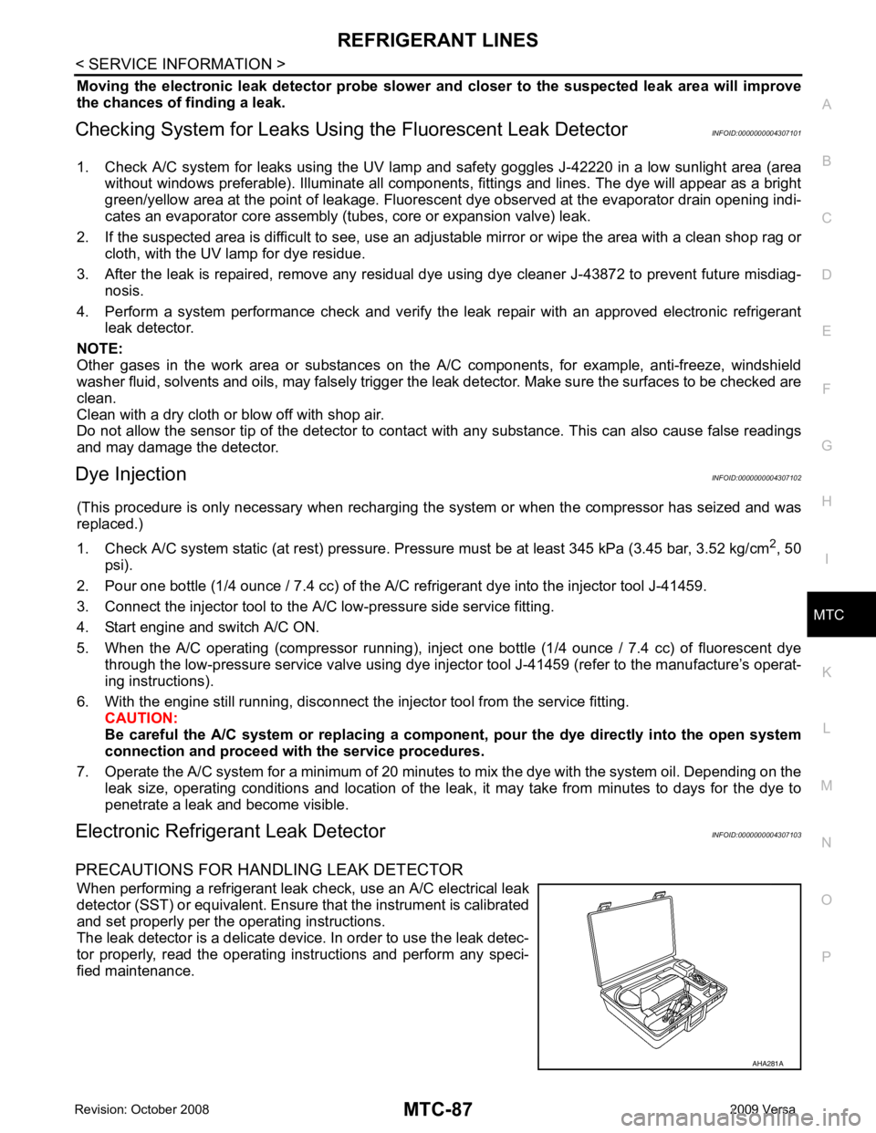
PRECAUTIONS FOR HANDLING LEAK DETECTOR When performing a refrigerant leak c heck, use an A/C electrical leak
detector (SST) or equivalent. Ensure that the instrument is calibrated
and set properly per the operating instructions.
The leak detector is a delicate device. In order to use the leak detec-
tor properly, read the operating instructions and perform any speci-
fied maintenance. AHA281A
Page 3974 of 4331
MTC
N
O P
Check all around the service valves. Ensure service valve caps are secured on the service valves (to
prevent leaks).
NOTE:
After removing A/C manifold gauge set from service va lves, wipe any residue from valves to prevent any
false readings by leak detector.
• Cooling unit (Evaporator)
With engine OFF, turn blower fan on “High” for at least 15 seconds to dissipate any refrigerant trace in
the cooling unit. Wait a minimum of 10 minutes ac cumulation time (refer to the manufacturer’s recom-
mended procedure for actual wait time) before inserting the leak detector probe into the drain hose.
Keep the probe inserted for at least 10 seconds. Use c aution not to contaminate the probe tip with water
or dirt that may be in the drain hose.
5. If a leak detector detects a leak, verify at least once by blowing compressed air into area of suspected
leak, then repeat check as outlined above.
6. Do not stop when one leak is found. Continue to check for additional leaks at all system components.
If no leaks are found, perform steps 7-10.
7. Start engine.
8. Set the heater A/C control as follows;
a. A/C switch: ON
b. Mode control dial position: VENT (Ventilation)
c. Intake door lever position: Recirculation
d. Max. cold temperature
e. Fan speed: High
9. Run engine at 1,500 rpm for at least 2 minutes.
10. Turn engine off and perform leak check again following steps 4 through 6 above.
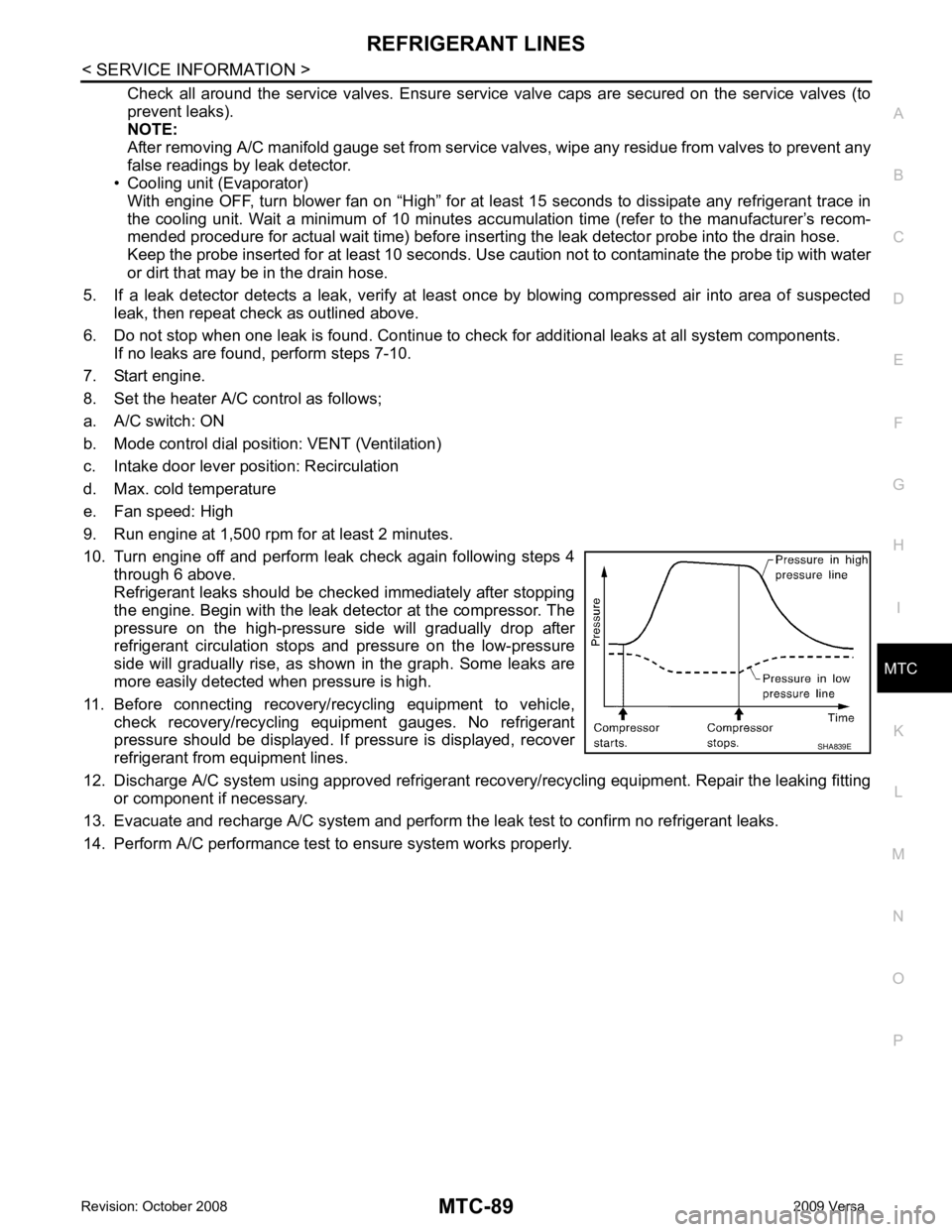
Refrigerant leaks should be chec ked immediately after stopping
the engine. Begin with the leak detector at the compressor. The
pressure on the high-pressure side will gradually drop after
refrigerant circulation stops and pressure on the low-pressure
side will gradually rise, as shown in the graph. Some leaks are
more easily detected when pressure is high.
11. Before connecting recovery/recycling equipment to vehicle, check recovery/recycling equipment gauges. No refrigerant
pressure should be displayed. If pressure is displayed, recover
refrigerant from equipment lines.
12. Discharge A/C system using approved refrigerant reco very/recycling equipment. Repair the leaking fitting
or component if necessary.
13. Evacuate and recharge A/C system and perform the l eak test to confirm no refrigerant leaks.
14. Perform A/C performance test to ensure system works properly.
Page 4062 of 4331
Removal and Instal-
lation " .
CHECKING STEERING WHEEL PLAY
• Turn steering wheel so that front wheels come to the straight-ahead position. Start engine and lightly turn
steering wheel to the left and right until front wheels start to move. Measure steering wheel movement on the
outer circumference.
• When the measurement value is outside the standard val ue, check backlash for each joint of steering col-
umn assembly and installation condition of steering gear assembly.
CHECKING NEUTRAL POSITION STEERING WHEEL
• Make sure that steering gear assembly, steering colu mn assembly and steering wheel are installed in the
correct position.
• Perform neutral position inspection after wheel alignment. Refer to PS-2, " Precaution for Supplemental
Restraint System (SRS) "AIR BA
G" and "SEAT BELT PRE-TENSIONER" " .
• Set vehicle to the straight-ahead position and c onfirm steering wheel is in the neutral position.
• Loosen outer socket lock nut and turn inner socket to left and right equally to make fine adjustments if steer-
ing wheel is not in the neutral position.
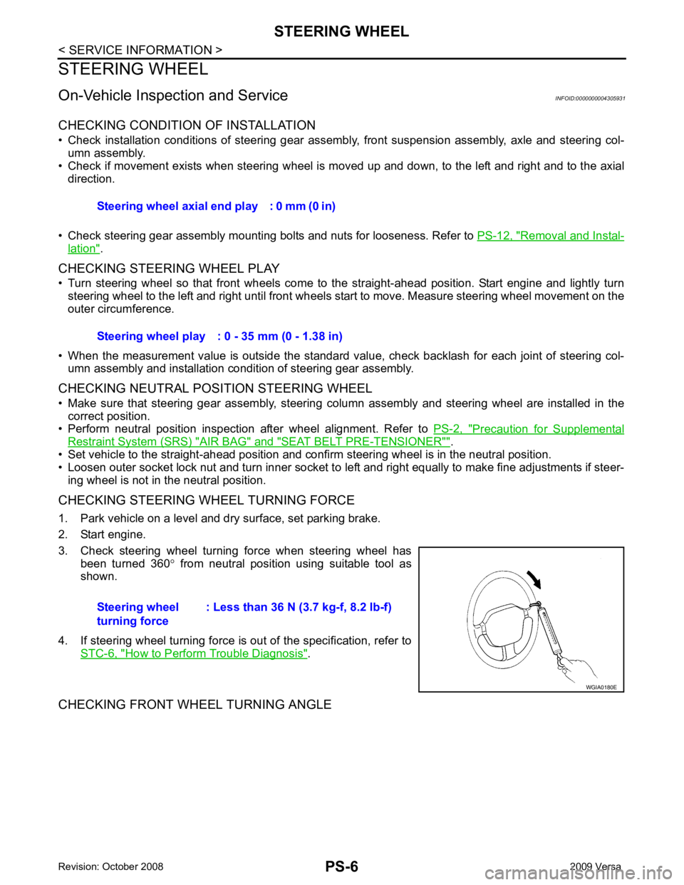
CHECKING STEERING WHEEL TURNING FORCE
1. Park vehicle on a level and dry surface, set parking brake.
2. Start engine.
3. Check steering wheel turning force when steering wheel has been turned 360 ° from neutral position using suitable tool as
shown.
4. If steering wheel turning force is out of the specification, refer to STC-6, " How to Perform Trouble Diagnosis " .
CHECKING FRONT WHEEL TURNING ANGLE Steering wheel axial end play : 0 mm (0 in)
Steering wheel play : 0 - 35 mm (0 - 1.38 in)
Steering wheel
turning force : Less than 36 N (3.7 kg-f, 8.2 lb-f)
Page 4063 of 4331
PS
N
O P
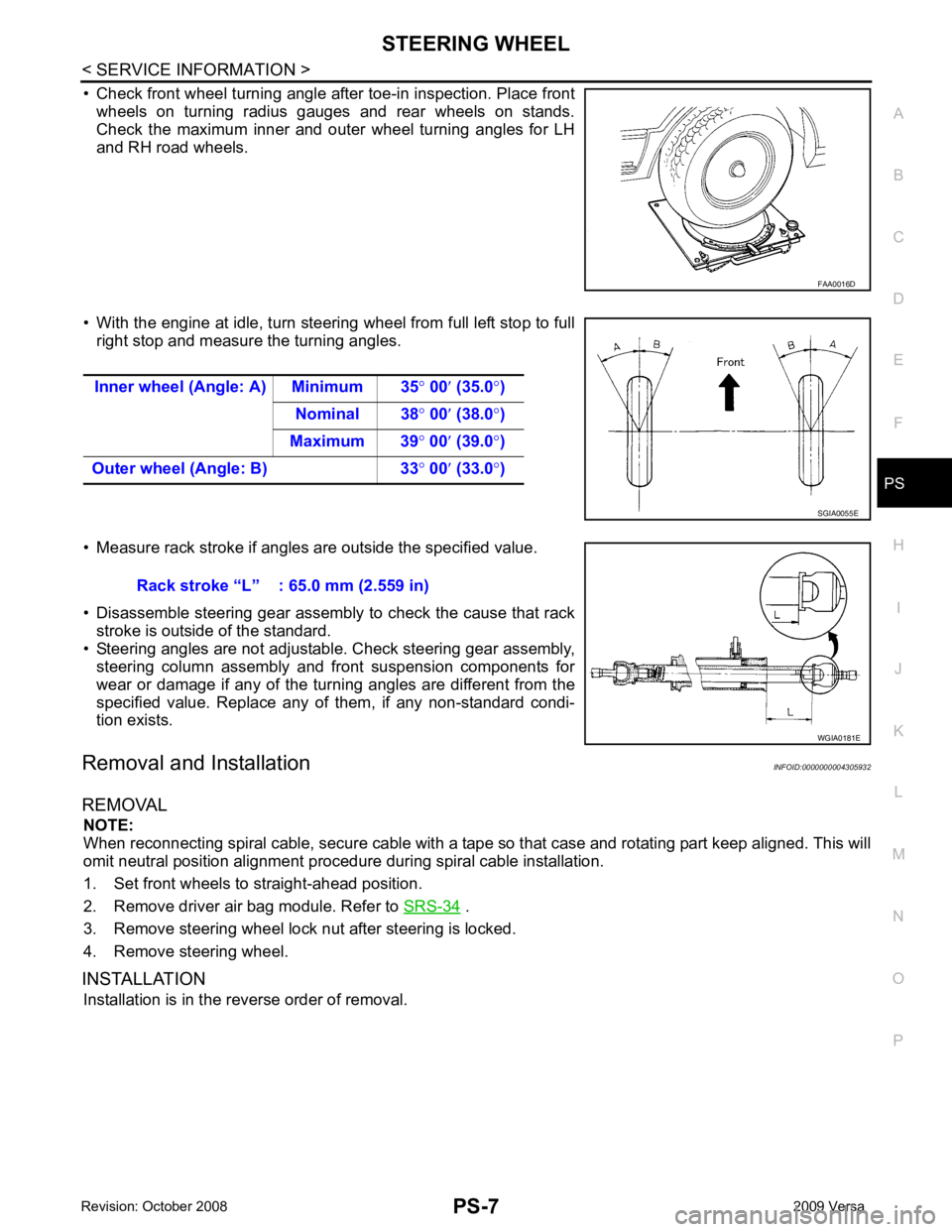
• Check front wheel turning angle after toe-in inspection. Place front
wheels on turning radius gauges and rear wheels on stands.
Check the maximum inner and outer wheel turning angles for LH
and RH road wheels.
• With the engine at idle, turn steering wheel from full left stop to full right stop and measure the turning angles.
• Measure rack stroke if angles are outside the specified value.
• Disassemble steering gear assembly to check the cause that rack stroke is outside of the standard.
• Steering angles are not adjustabl e. Check steering gear assembly,
steering column assembly and front suspension components for
wear or damage if any of the turning angles are different from the
specified value. Replace any of them, if any non-standard condi-
tion exists.
Removal and Installation INFOID:0000000004305932
REMOVAL NOTE:
When reconnecting spiral cable, secure cable with a tape so that case and rotating part keep aligned. This will
omit neutral position alignment procedure during spiral cable installation.
1. Set front wheels to straight-ahead position.
2. Remove driver air bag module. Refer to SRS-34 .
3. Remove steering wheel lock nut after steering is locked.
4. Remove steering wheel.
INSTALLATION Installation is in the reverse order of removal.
Page 4114 of 4331

RSU
N
O P
5. When the repair work is completed, return the ignition switch to the
″LOCK ″ position before connecting
the battery cables. (At this time, the steering lock mechanism will engage.)
6. Perform a self-diagnosis check of al l control units using CONSULT-III.
Precaution for Rear Suspension INFOID:0000000004305875
• When installing the rubber bushings, the final tightening must be done under unladen condition and with the tires on level ground. Oil will shorten the life of the rubber bushings, so wipe off any spilled oil immediately.
• Unladen condition means the fuel tank, engine coolant and l ubricants are at the full specification. The spare
tire, jack, hand tools, and mats are in their designated positions.
• After installing suspension components, check the wheel alignment.
• Caulking nuts are not reusable. Always use new caulking nuts for installation. New caulking nuts are pre-
oiled, do not apply any additional lubrication.
Page 4141 of 4331
SC
N
O P
BATTERY
How to Handle Battery INFOID:0000000004306818
CAUTION:
• If it becomes necessary to start the engine with a booster battery and jumper cables, use a 12-volt
booster battery.
• After connecting battery cables, ensure that they are tightly clamped to battery terminals for good
contact.
• Never add distilled water through the hole used to check specific gravity.
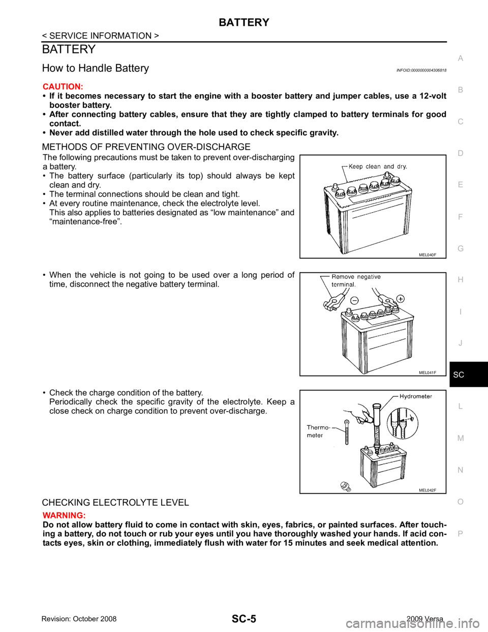
METHODS OF PREVENTING OVER-DISCHARGE The following precautions must be taken to prevent over-discharging
a battery.
• The battery surface (particularly its top) should always be kept clean and dry.
• The terminal connections should be clean and tight.
• At every routine maintenance, check the electrolyte level. This also applies to batteries designated as “low maintenance” and
“maintenance-free”.
• When the vehicle is not going to be used over a long period of time, disconnect the negative battery terminal.
• Check the charge condition of the battery. Periodically check the specific gr avity of the electrolyte. Keep a
close check on charge condition to prevent over-discharge.
CHECKING ELECTROLYTE LEVEL WARNING:
Do not allow battery fluid to come in contact with skin, eyes, fabrics, or painted surfaces. After touch-
ing a battery, do not touch or rub your eyes until yo u have thoroughly washed your hands. If acid con-
tacts eyes, skin or clothing, imme diately flush with water for 15 minutes and seek medical attention. MEL041F