2009 NISSAN LATIO check engine
[x] Cancel search: check enginePage 3787 of 4331
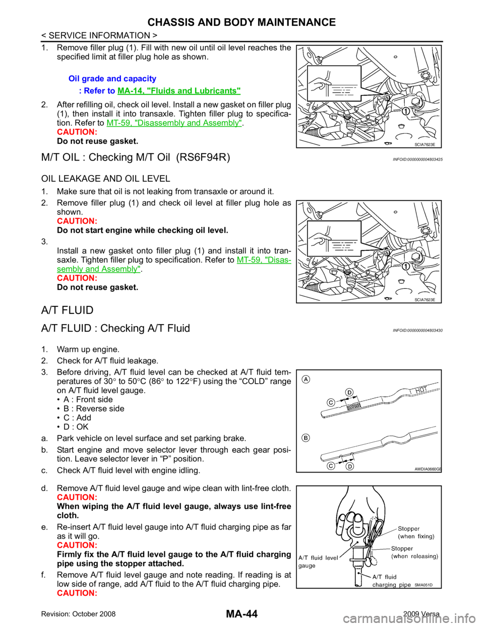
Disassembly and Assembly " .
CAUTION:
Do not reuse gasket.
M/T OIL : Checking M/T Oil (RS6F94R) INFOID:0000000004803425
OIL LEAKAGE AND OIL LEVEL
1. Make sure that oil is not leaking from transaxle or around it.
2. Remove filler plug (1) and check oil level at filler plug hole as shown.
CAUTION:
Do not start engine wh ile checking oil level.
3. Install a new gasket onto filler plug (1) and install it into tran-
saxle. Tighten filler plug to specification. Refer to MT-59, " Disas-
sembly and Assembly " .
CAUTION:
Do not reuse gasket.
A/T FLUID
A/T FLUID : Checking A/T Fluid INFOID:0000000004803430
1. Warm up engine.
2. Check for A/T fluid leakage.
3. Before driving, A/T fluid level can be checked at A/T fluid tem- peratures of 30 ° to 50 °C (86 ° to 122 °F) using the “COLD” range
on A/T fluid level gauge.
• A : Front side
• B : Reverse side
• C : Add
• D : OK
a. Park vehicle on level surface and set parking brake.
b. Start engine and move selector lever through each gear posi- tion. Leave selector lever in “P” position.
c. Check A/T fluid level with engine idling.
d. Remove A/T fluid level gauge and wipe clean with lint-free cloth. CAUTION:
When wiping the A/T fluid level gauge, always use lint-free
cloth.
e. Re-insert A/T fluid level gauge into A/T fluid charging pipe as far as it will go.
CAUTION:
Firmly fix the A/T fluid level ga uge to the A/T fluid charging
pipe using the stopper attached.
f. Remove A/T fluid level gauge and note reading. If reading is at low side of range, add A/T fluid to the A/T fluid charging pipe.
CAUTION: Oil grade and capacity
: Refer to MA-14, " Fluids and Lubricants "
SCIA7623E
B
Page 3788 of 4331
MA
N
O P
Do not overfill.
4. Drive vehicle for approximately 5 minutes.
5. Re-check A/T fluid level at A/T fluid temperatures of 50° to 80 °C (122 ° to 176 °F) using “HOT” range on A/
T fluid level gauge.
CAUTION:
• When wiping the A/T fluid level gauge, always use lint-free cloth.
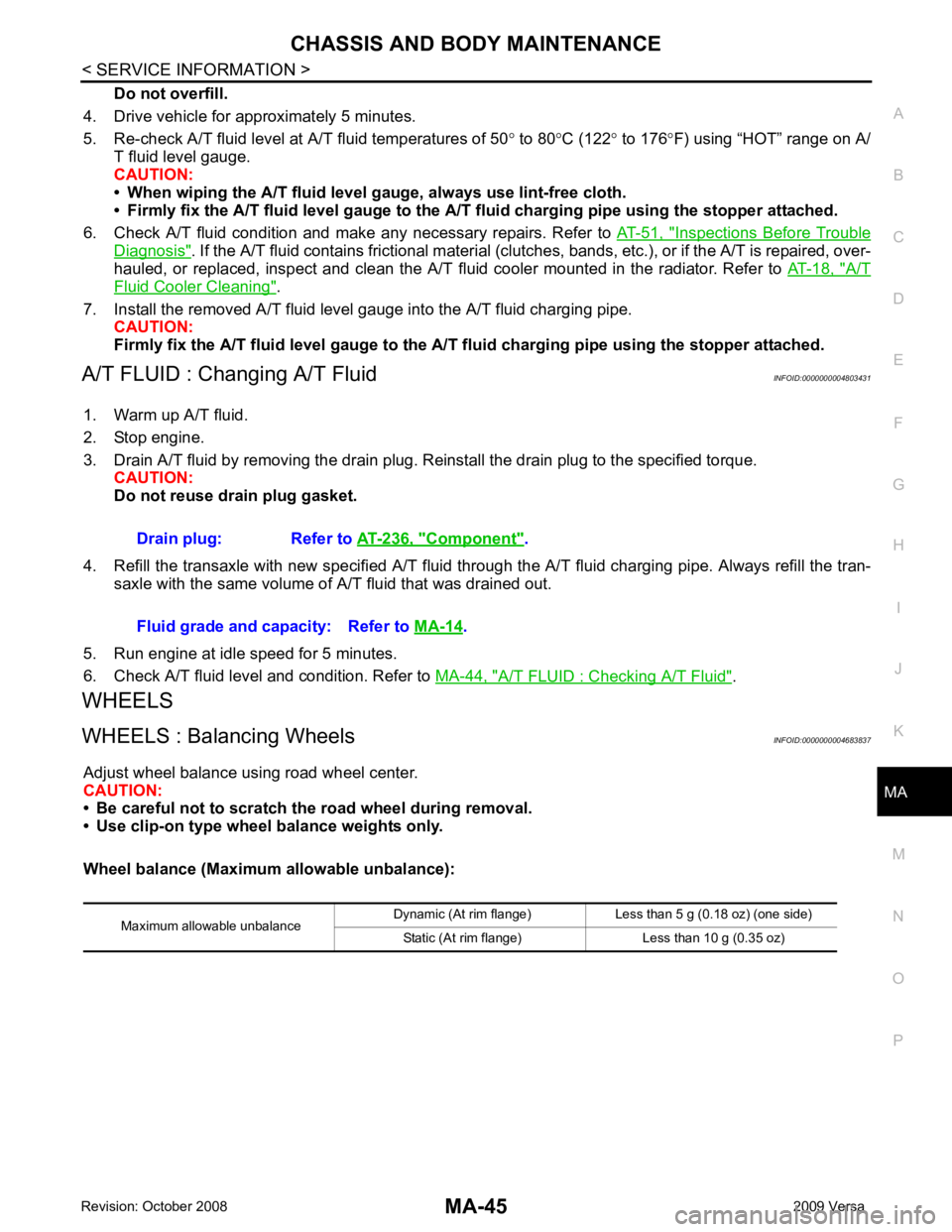
• Firmly fix the A/T fluid level ga uge to the A/T fluid charging pipe using the stopper attached.
6. Check A/T fluid condition and make any necessary repairs. Refer to AT-51, " Inspections Before Trouble
Diagnosis " . If the A/T fluid contains frictional material (clu
tches, bands, etc.), or if the A/T is repaired, over-
hauled, or replaced, inspect and clean the A/T fluid cooler mounted in the radiator. Refer to AT-18, " A/T
Fluid Cooler Cleaning " .
7. Install the removed A/T fluid level gauge into the A/T fluid charging pipe. CAUTION:
Firmly fix the A/T fluid level gaug e to the A/T fluid charging pipe using the stopper attached.
A/T FLUID : Changing A/T Fluid INFOID:0000000004803431
1. Warm up A/T fluid.
2. Stop engine.
3. Drain A/T fluid by removing the drain plug. Re install the drain plug to the specified torque.
CAUTION:
Do not reuse drain plug gasket.
4. Refill the transaxle with new specified A/T fluid th rough the A/T fluid charging pipe. Always refill the tran-
saxle with the same volume of A/T fluid that was drained out.
5. Run engine at idle speed for 5 minutes.
6. Check A/T fluid level and condition. Refer to MA-44, " A/T FLUID : Checking A/T Fluid " .
WHEELS
WHEELS : Balancing Wheels INFOID:0000000004683837
Adjust wheel balance using road wheel center.
CAUTION:
• Be careful not to scratch th e road wheel during removal.
• Use clip-on type wheel balance weights only.
Wheel balance (Maximum allowable unbalance): Drain plug: Refer to
AT-236, " Component " .
Fluid grade and capacity: Refer to MA-14 .
Maximum allowable unbalance Dynamic (At rim flange) Less than 5 g (0.18 oz) (one side)
Static (At rim flange) Less than 10 g (0.35 oz)
Page 3804 of 4331
![NISSAN LATIO 2009 Service Repair Manual MT-10< SERVICE INFORMATION >
[RS5F91R]
M/T OIL
M/T OIL
Draining INFOID:0000000004784220
1. Start engine and let it run to warm up transaxle.
2. Stop engine. Remove drain plug (1) and drain oil.
3. Set NISSAN LATIO 2009 Service Repair Manual MT-10< SERVICE INFORMATION >
[RS5F91R]
M/T OIL
M/T OIL
Draining INFOID:0000000004784220
1. Start engine and let it run to warm up transaxle.
2. Stop engine. Remove drain plug (1) and drain oil.
3. Set](/manual-img/5/57359/w960_57359-3803.png)
MT-10< SERVICE INFORMATION >
[RS5F91R]
M/T OIL
M/T OIL
Draining INFOID:0000000004784220
1. Start engine and let it run to warm up transaxle.
2. Stop engine. Remove drain plug (1) and drain oil.
3. Set a new gasket on drain plug (1) and install it to transaxle and tighten drain plug to the specified torque. Refer to MT-17, " Dis-
assembly and Assembly " .
CAUTION:
Do not reuse gasket.
Refilling INFOID:0000000004784221
1. Remove filler plug (1). Fill with new oil until oil level reaches the specified limit near filler plug hole as shown.
2. After refilling oil, check oil level.
3. Set a new gasket on filler plug (1), then install it to transaxle and tighten to the specified torque. Refer to MT-17, " Disassembly
and Assembly " .
CAUTION:
Do not reuse gasket.
Inspection INFOID:0000000004784222
LEAKAGE
Make sure that oil is not leaking from transaxle or around it.
LEVEL
1. Remove filler plug (1) and check oil level at filler plug hole as shown.
CAUTION:
Do not start engine wh ile checking oil level.
2. Set a new gasket on filler plug (1) and install it to the transaxle case.
CAUTION:
Do not reuse gasket.
3. Tighten filler plug to the specified torque. Refer to MT-17, " Dis-
assembly and Assembly " . PCIB1504E
Oil grade and capacity : Refer to
MA-14, " Fluids and
Lubricants " .
SCIA7119E
SCIA7119E
Page 3811 of 4331
MT
N
O P
Installation is in the reverse order of removal.
CAUTION:
• Make sure the transaxle assembly does not interfer e with the wire harnesses and clutch tube.
• When installing transaxle assembly, do not bring input shaft into contact with clutch cover.
• If transaxle is removed from the vehicle, always replace CSC. Refer to CL-12, " Removal and Installa-
tion " .
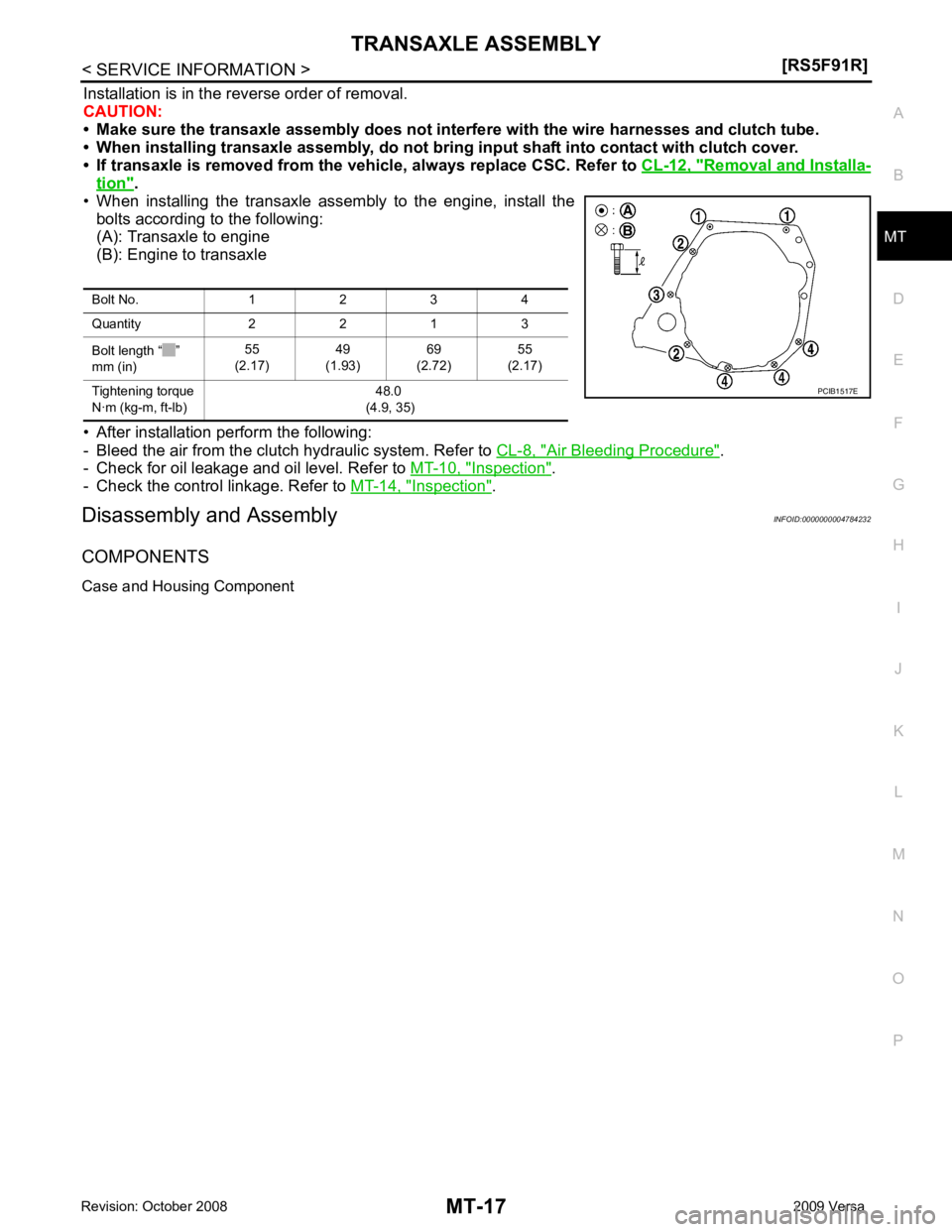
• When installing the transaxle assembly to the engine, install the bolts according to the following:
(A): Transaxle to engine
(B): Engine to transaxle
• After installation perform the following:
- Bleed the air from the clutch hydraulic system. Refer to CL-8, " Air Bleeding Procedure " .
- Check for oil leakage and oil level. Refer to MT-10, " Inspection " .
- Check the control linkage. Refer to MT-14, " Inspection " .
Disassembly and Assembly INFOID:0000000004784232
COMPONENTS
Case and Housing Component Bolt No. 1 2 3 4
Quantity 2 2 1 3
Bolt length “ ”
mm (in) 55
(2.17) 49
(1.93) 69
(2.72) 55
(2.17)
Tightening torque
N·m (kg-m, ft-lb) 48.0
(4.9, 35)
Page 3846 of 4331
Dis-
assembly and Assembly " .
CAUTION:
Do not reuse gasket.
FILLING
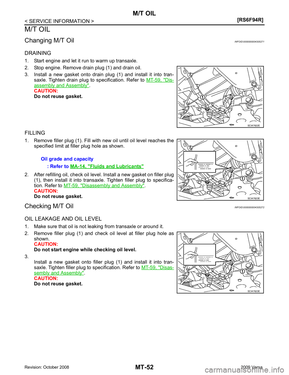
1. Remove filler plug (1). Fill with new oil until oil level reaches the specified limit at filler plug hole as shown.
2. After refilling oil, check oil level. Install a new gasket on filler plug (1), then install it into transaxle. Tighten filler plug to specifica-
tion. Refer to MT-59, " Disassembly and Assembly " .
CAUTION:
Do not reuse gasket.
Checking M/T Oil INFOID:0000000004305272
OIL LEAKAGE AND OIL LEVEL
1. Make sure that oil is not leaking from transaxle or around it.
2. Remove filler plug (1) and check oil level at filler plug hole as shown.
CAUTION:
Do not start engine wh ile checking oil level.
3. Install a new gasket onto filler plug (1) and install it into tran-
saxle. Tighten filler plug to specification. Refer to MT-59, " Disas-
sembly and Assembly " .
CAUTION:
Do not reuse gasket. Fluids and Lubricants "
Page 3853 of 4331
MT
N
O P
Installation is in the reverse order of removal.
CAUTION:
When installing transaxle assembly, be careful not to bring transaxle input shaft into contact with
clutch cover.
• If transaxle is removed from the v ehicle, always replace CSC. Refer to CL-12, " Removal and Installation " .
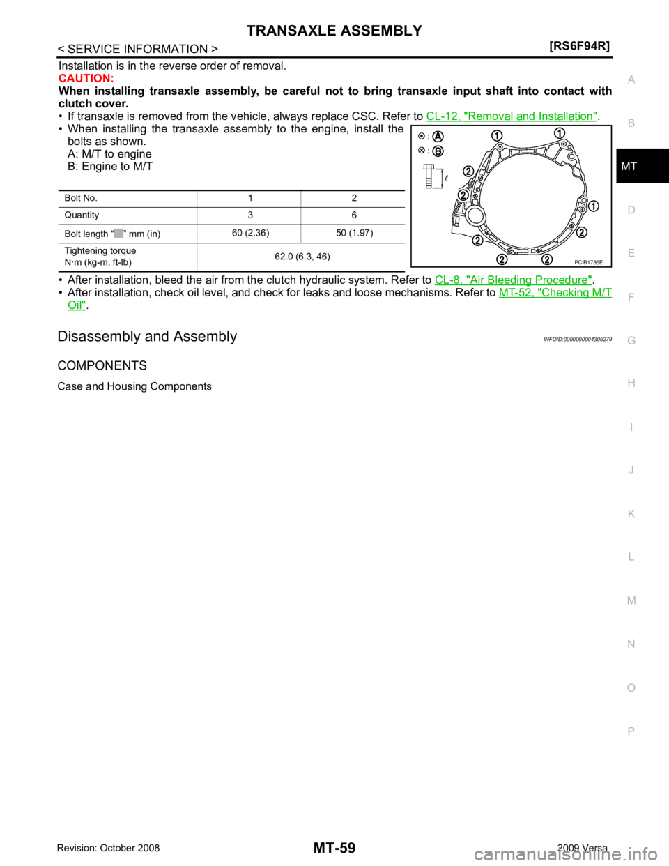
• When installing the transaxle assembly to the engine, install the
bolts as shown.
A: M/T to engine
B: Engine to M/T
• After installation, bleed the air from the clutch hydraulic system. Refer to CL-8, " Air Bleeding Procedure " .
• After installation, check oil level, and check for leaks and loose mechanisms. Refer to MT-52, " Checking M/T
Oil " .
Disassembly and Assembly INFOID:0000000004305279
COMPONENTS
Case and Housing Components Bolt No. 1 2
Quantity 3 6
Bolt length “ ” mm (in) 60 (2.36) 50 (1.97)
Tightening torque
N·m (kg-m, ft-lb) 62.0 (6.3, 46)
Page 3893 of 4331
Maintenance of Oil Quantity in Compressor " .
• Keep friction surfaces between clut ch and pulley clean. If the surface is contaminated, with oil, wipe
it off by using a clean waste cloth moistened with thinner.
• After compressor service operation, turn the compresso r shaft by hand more than five turns in both
directions. This will equally dist ribute oil inside the compressor. After the compressor is installed,
let the engine idle and operat e the compressor for one hour.
• After replacing the compressor magnet clutch, ap ply voltage to the new one and check for usual
operation.
Precaution for Service Equipment INFOID:0000000004307048
RECOVERY/RECYCLING EQUIPMENT
Be certain to follow the manufacturer’s instructions for machine operation and machine maintenance. Never
introduce any refrigerant other than that specified into the machine.
ELECTRONIC LEAK DETECTOR
Be certain to follow the manufacturer’s instruct ions for tester operation and tester maintenance.
VACUUM PUMP
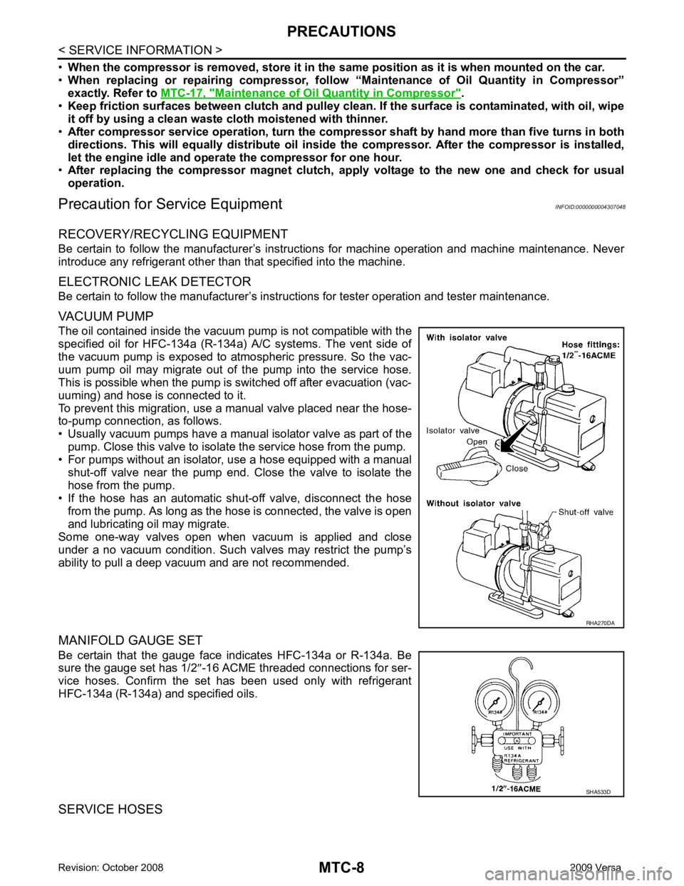
The oil contained inside the vacuum pump is not compatible with the
specified oil for HFC-134a (R-134a) A/C systems. The vent side of
the vacuum pump is exposed to atmospheric pressure. So the vac-
uum pump oil may migrate out of the pump into the service hose.
This is possible when the pump is switched off after evacuation (vac-
uuming) and hose is connected to it.
To prevent this migration, use a manual valve placed near the hose-
to-pump connection, as follows.
• Usually vacuum pumps have a manual isolator valve as part of the pump. Close this valve to isolat e the service hose from the pump.
• For pumps without an isolator, use a hose equipped with a manual
shut-off valve near the pump end. Close the valve to isolate the
hose from the pump.
• If the hose has an automatic shut -off valve, disconnect the hose
from the pump. As long as the hose is connected, the valve is open
and lubricating oil may migrate.
Some one-way valves open when vacuum is applied and close
under a no vacuum condition. Such valves may restrict the pump’s
ability to pull a deep vacuum and are not recommended.
MANIFOLD GAUGE SET
Be certain that the gauge face indicates HFC-134a or R-134a. Be
sure the gauge set has 1/2 ″-16 ACME threaded connections for ser-
vice hoses. Confirm the set has been used only with refrigerant
HFC-134a (R-134a) and specified oils.
SERVICE HOSES SHA533D
Page 3944 of 4331
MTC
N
O P
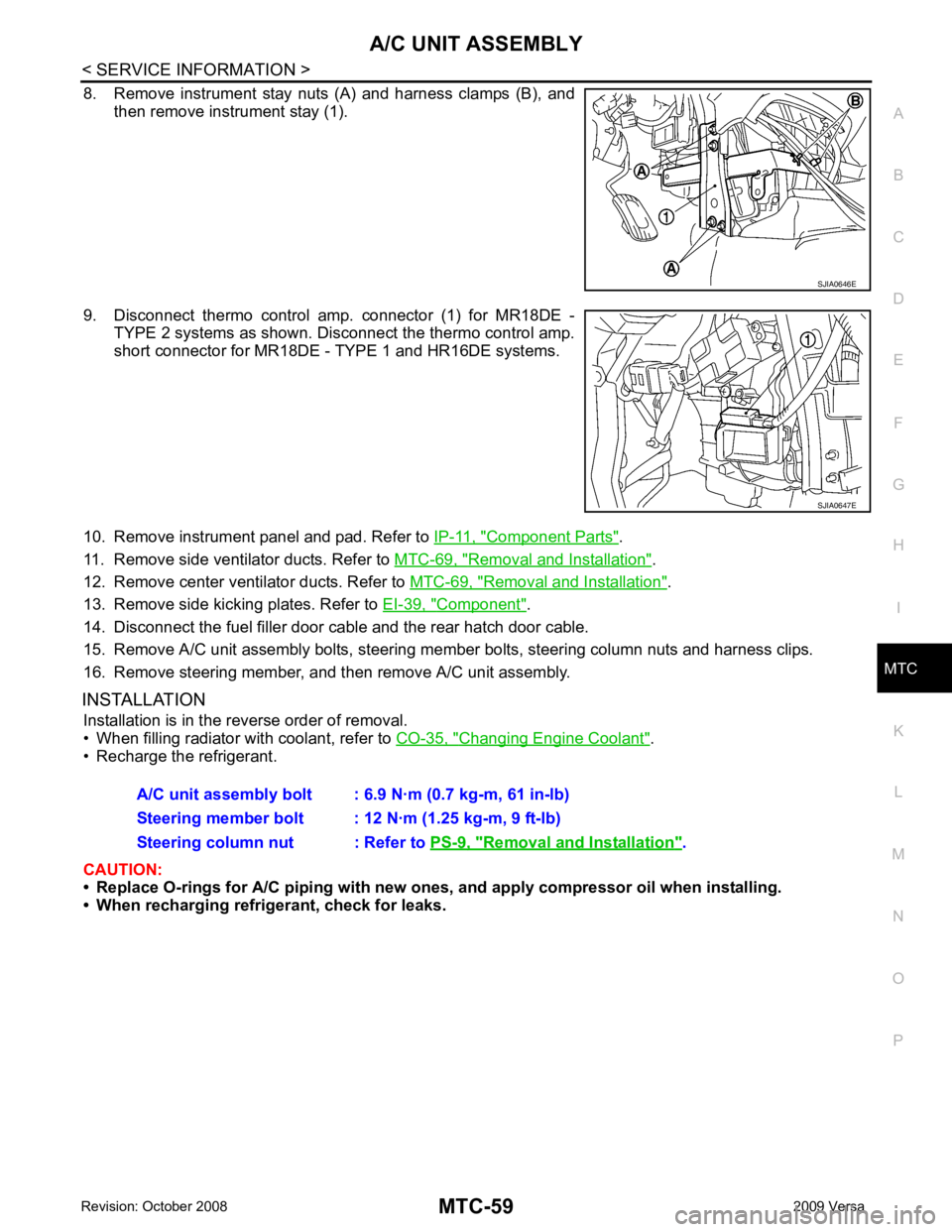
8. Remove instrument stay nuts (A) and harness clamps (B), and
then remove instrument stay (1).
9. Disconnect thermo control amp. connector (1) for MR18DE - TYPE 2 systems as shown. Disconnect the thermo control amp.
short connector for MR18DE - TYPE 1 and HR16DE systems.
10. Remove instrument panel and pad. Refer to IP-11, " Component Parts " .
11. Remove side ventilator ducts. Refer to MTC-69, " Removal and Installation " .
12. Remove center ventilator ducts. Refer to MTC-69, " Removal and Installation " .
13. Remove side kicking plates. Refer to EI-39, " Component " .
14. Disconnect the fuel filler door cable and the rear hatch door cable.
15. Remove A/C unit assembly bolts, steering member bolts, steering column nuts and harness clips.
16. Remove steering member, and then remove A/C unit assembly.
INSTALLATION Installation is in the reverse order of removal.
• When filling radiator with coolant, refer to CO-35, " Changing Engine Coolant " .
• Recharge the refrigerant.
CAUTION:
• Replace O-rings for A/C piping with new on es, and apply compressor oil when installing.
• When recharging refrigerant, check for leaks. Removal and Installation " .