2009 NISSAN LATIO check engine
[x] Cancel search: check enginePage 3144 of 4331
EM
NP
O
24. Remove A/C compressor with piping connected from t
he engine. Temporarily secure it on the vehicle side
with a rope to avoid putting load on it. Refer to MTC-80, " Removal and Installation of Compressor -
MR18DE " .
25. Remove the intake manifold to prevent the hanging chain from interfering. Refer to EM-141, " Compo-
nent " .
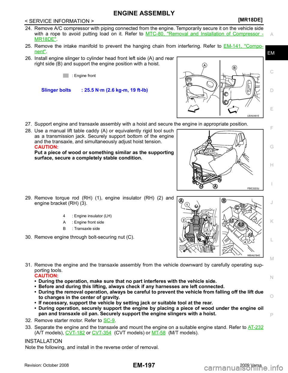
26. Install engine slinger to cylinder head front left side (A) and rear right side (B) and support the engine position with a hoist.
27. Support engine and transaxle assembly with a hoist and secure the engine in appropriate position.
28. Use a manual lift table caddy (A) or equivalently rigid tool such as a transmission jack. Securely support bottom of the engine
and the transaxle, and simultaneously adjust hoist tension.
CAUTION:
Put a piece of wood or someth ing similar as the supporting
surface, secure a completely stable condition.
29. Remove torque rod (RH) (1), engine insulator (RH) (2) and engine bracket (RH) (3).
30. Remove engine through bolt-securing nut (C).
31. Remove the engine and the transaxle assembly from the vehicle downward by carefully operating sup- porting tools.
CAUTION:
• During the operation, make sure that no part interferes with the vehicle side.
• Before and during this lifting, alw ays check if any harnesses are left connected.
• During the removal operation, alw ays be careful to prevent the vehicle from falling off the lift due
to changes in the center of gravity.
• If necessary, support the vehicle by setting jack or suitable tool at the rear.
• During operation, securely suppor t the engine by placing a piece of wood under the engine oil
pan and transaxle oil pan. Securely sup port the engine slingers with a hoist.
32. Remove starter motor. Refer to SC-9 .
33. Separate the engine and the transaxle and mount the engine on a suitable engine stand. Refer to AT-232(A/T models),
CVT-182 or
CVT-354 (CVT models) or
MT-58 (M/T models).
INSTALLATION Note the following, and install in the reverse order of removal. : Engine front
Slinger bolts : 25.5 N·m (2.6 kg-m, 19 ft-lb) PBIC3223J
Page 3145 of 4331
Com-
ponent " .
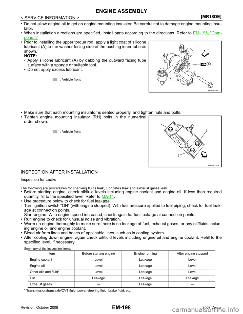
• Prior to installing the upper torque rod, apply a light coat of silicone lubricant (A) to the washer facing side of the bushing inner tube as
shown.
NOTE:
• Apply silicone lubricant (A) by dabbing the outward facing tube
surface with a sponge or suitable tool.
• Do not apply excess lubricant.
• Make sure that each mounting insulator is seated properly, and tighten nuts and bolts.
• Tighten engine mounting insulator (RH) bolts in the numerical order shown.
INSPECTION AFTER INSTALLATION
Inspection for Leaks
The following are procedures for checking fluids leak, lubricates leak and exhaust gases leak.
• Before starting engine, check oil/fluid levels incl uding engine coolant and engine oil. If less than required
quantity, fill to the specified level. Refer to MA-14 .
• Use procedure below to check for fuel leakage.
- Turn ignition switch “ON” (with engine stopped). With fuel pressure applied to fuel piping, check for fuel leak-
age at connection points.
- Start engine. With engine speed increased, che ck again for fuel leakage at connection points.
• Run engine to check for unusual noise and vibration.
• Warm up engine thoroughly to make sure there is no leak age of fuel, exhaust gases, or any oil/fluids includ-
ing engine oil and engine coolant.
• Bleed air from lines and hoses of applicable lines, such as in cooling system.
• After cooling down engine, again check oil/fluid levels including engine oil and engine coolant. Refill to the specified level, if necessary.
Summary of the inspection items:
* Transmission/transaxle/CVT fluid, power steering fluid, brake fluid, etc. : Vehicle front
Page 3152 of 4331
EM
NP
O
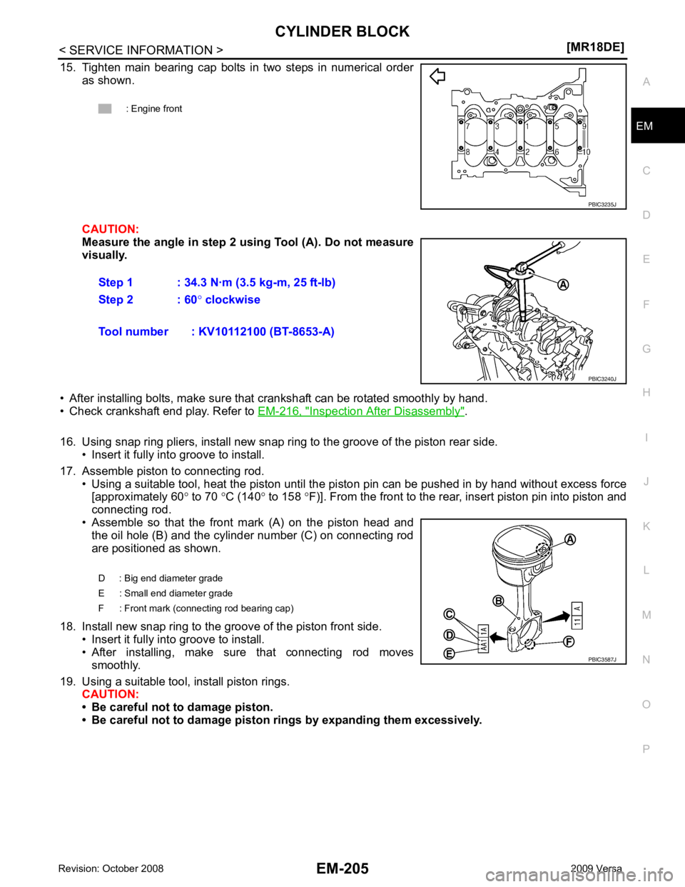
15. Tighten main bearing cap bolts in two steps in numerical order
as shown.
CAUTION:
Measure the angle in step 2 us ing Tool (A). Do not measure
visually.
• After installing bolts, make sure that crankshaft can be rotated smoothly by hand.
• Check crankshaft end play. Refer to EM-216, " Inspection After Disassembly " .
16. Using snap ring pliers, install new snap ring to the groove of the piston rear side. • Insert it fully into groove to install.
17. Assemble piston to connecting rod. • Using a suitable tool, heat the piston until the pi ston pin can be pushed in by hand without excess force
[approximately 60 ° to 70 °C (140 ° to 158 °F)]. From the front to the rear, insert piston pin into piston and
connecting rod.
• Assemble so that the front mark (A) on the piston head and the oil hole (B) and the cylinder number (C) on connecting rod
are positioned as shown.
18. Install new snap ring to the groove of the piston front side. • Insert it fully into groove to install.
• After installing, make sure that connecting rod moves smoothly.
19. Using a suitable tool, install piston rings. CAUTION:
• Be careful not to damage piston.
• Be careful not to damage piston rings by expanding them excessively.
: Engine front
Page 3153 of 4331
![NISSAN LATIO 2009 Service Repair Manual EM-206< SERVICE INFORMATION >
[MR18DE]
CYLINDER BLOCK
• Position each ring with the gap as shown referring to the pis- ton front mark.
CAUTION:
Never contact the rail end gap under NISSAN LATIO 2009 Service Repair Manual EM-206< SERVICE INFORMATION >
[MR18DE]
CYLINDER BLOCK
• Position each ring with the gap as shown referring to the pis- ton front mark.
CAUTION:
Never contact the rail end gap under](/manual-img/5/57359/w960_57359-3152.png)
EM-206< SERVICE INFORMATION >
[MR18DE]
CYLINDER BLOCK
• Position each ring with the gap as shown referring to the pis- ton front mark.
CAUTION:
Never contact the rail end gap under the oil ring with the
oil drain cast groove of piston.
• Install second ring with the stamped surface facing upward.
20. Install connecting rod bearing upper (2) and lower (3) to con- necting rod (1) and connecting rod cap (4).
• Install the connecting rod in the dimension shown.
• Make sure that connecting rod bearing oil hole (A) is com- pletely in the inside of connecting rod oil hole chamfered area
(B).
• When installing connecting rod bearings, apply new engine oil to the bearing surface (inside). Do not apply new engine oil to
the back surface, but thoroughly clean it.
NOTE:
• There is no positioning tab.
• Install the connecting rod bearings in the center of connect-
ing rod and connecting rod bearing cap as shown. For ser-
vice operation, the center position can be checked, visually.
21. Install piston and connecting rod assembly to crankshaft. • Position crankshaft pin corresponding to connecting rod to be installed onto the bottom dead center.
• Apply new engine oil sufficiently to the cylinder bore, piston and crankshaft pin.
• Match the cylinder position with the cylinder number (C) on connecting rod to install.
• Install so that front mark (A) on the piston head faces the front of engine.A : Oil ring upper or lower rail gap
B : Front mark
C : Second ring and oil ring spacer gap
D : Top ring gap
E : Stamped mark PBIC3588J
C : Oil hole (connecting rod)
D : Arrow view
: Engine front PBIC4541E
B : Oil hole
D : Big end diameter grade
E : Small end diameter grade
F : Front mark (connecting rod bearing cap) PBIC3587J
Page 3154 of 4331
EM
NP
O
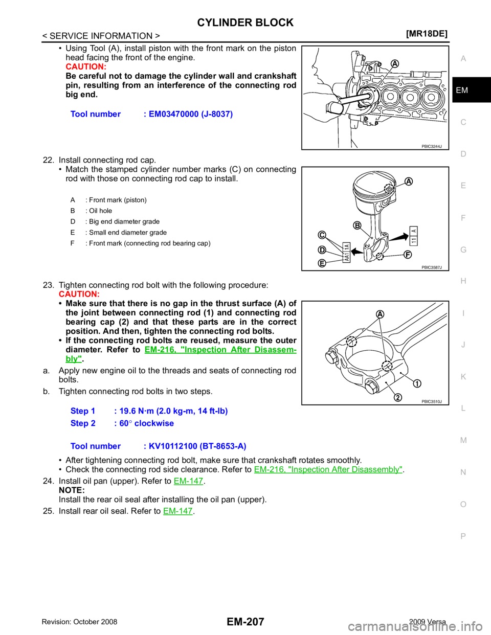
• Using Tool (A), install piston with the front mark on the piston
head facing the front of the engine.
CAUTION:
Be careful not to damage the cylinder wall and crankshaft
pin, resulting from an inte rference of the connecting rod
big end.
22. Install connecting rod cap. • Match the stamped cylinder number marks (C) on connectingrod with those on connecting rod cap to install.
23. Tighten connecting rod bolt with the following procedure: CAUTION:
• Make sure that there is no gap in the thrust surface (A) of
the joint between connecting rod (1) and connecting rod
bearing cap (2) and that these parts are in the correct
position. And then, tighten the connecting rod bolts.
• If the connecting rod bolts ar e reused, measure the outer
diameter. Refer to EM-216, " Inspection After Disassem-
bly " .
a. Apply new engine oil to the threads and seats of connecting rod bolts.
b. Tighten connecting rod bolts in two steps.
• After tightening connecting rod bolt, make sure that crankshaft rotates smoothly.
• Check the connecting rod side clearance. Refer to EM-216, " Inspection After Disassembly " .
24. Install oil pan (upper). Refer to EM-147 .
NOTE:
Install the rear oil seal after installing the oil pan (upper).
25. Install rear oil seal. Refer to EM-147 .
Tool number : EM03470000 (J-8037)
Page 3156 of 4331
EM
NP
O
How to Select Piston and Bearing
INFOID:0000000004307160
DESCRIPTION
• The identification grade stamped on each part is the grade for the dimension measured in new condition.
This grade cannot apply to reused parts.
• For reused or repaired parts, measure the dimens ion accurately. Determine the grade by comparing the
measurement with the values of each selection table.
• For details of the measurement method of each part , the reuse standards and the selection method of the
selective fitting parts, follow the applicable procedures.
HOW TO SELECT PISTON
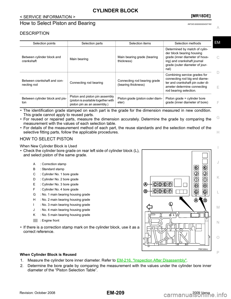
When New Cylinder Block is Used • Check the cylinder bore grade on rear left side of cylinder block (L), and select piston of the same grade.
• If there is a correction stamp mark on the cylinder block, use it as a correct reference.
When Cylinder Block is Reused 1. Measure the cylinder bore inner diameter. Refer to EM-216, " Inspection After Disassembly " .
2. Determine the bore grade by comparing the measur ement with the values under the cylinder bore inner
diameter of the “Piston Selection Table”. Selection points Selection parts Selection items Selection methods
Between cylinder block and
crankshaft Main bearing
Main bearing grade (bearing
thickness) Determined by match of cylin-
der block bearing housing
grade (inner diameter of hous-
ing) and crankshaft journal
grade (outer diameter of jour-
nal)
Between crankshaft and con-
necting rod Connecting rod bearing
Connecting rod bearing grade
(bearing thickness) Combining service grades for
connecting rod big end diame-
ter and crankshaft pin outer di-
ameter determine connecting
rod bearing selection.
Between cylinder block and pis-
ton Piston and piston pin assembly
(piston is available together with
piston pin as an assembly.) Piston grade (piston outer diam-
eter) Piston grade = cylinder bore
grade (inner diameter of bore) A : Correction stamp
B : Standard stamp
C : Cylinder No. 1 bore grade
D : Cylinder No. 2 bore grade
E : Cylinder No. 3 bore grade
F : Cylinder No. 4 bore grade
G : No. 1 main bearing housing grade
H : No. 2 main bearing housing grade
I : No. 3 main bearing housing grade
J : No. 4 main bearing housing grade
K : No. 5 main bearing housing grade
: Engine front
Page 3191 of 4331
EX
NP
O
SERVICE INFORMATION
PRECAUTIONS
Precaution for Supplemental Restraint System (SRS) "AIR BAG" and "SEAT BELT
PRE-TENSIONER" INFOID:0000000004784390
The Supplemental Restraint System such as “A IR BAG” and “SEAT BELT PRE-TENSIONER”, used along
with a front seat belt, helps to reduce the risk or severi ty of injury to the driver and front passenger for certain
types of collision. This system includes seat belt switch inputs and dual stage front air bag modules. The SRS
system uses the seat belt switches to determine the front air bag deployment, and may only deploy one front
air bag, depending on the severity of a collision and w hether the front occupants are belted or unbelted.
Information necessary to service the system safely is included in the SRS and SB section of this Service Man-
ual.
WARNING:
• To avoid rendering the SRS inoper ative, which could increase the risk of personal injury or death in
the event of a collision which would result in air bag inflation, all maintenance must be performed by
an authorized NISSAN/INFINITI dealer.
• Improper maintenance, including in correct removal and installation of the SRS can lead to personal
injury caused by unintentional act ivation of the system. For removal of Spiral Cable and Air Bag
Module, see the SRS section.
• Do not use electrical test equipm ent on any circuit related to the SRS unless instructed to in this
Service Manual. SRS wiring harnesses can be identi fied by yellow and/or orange harnesses or har-
ness connectors.
• When working near the Airbag Diagnosis Sensor Un it or other Airbag System sensors with the Igni-
tion ON or engine running, DO NOT use air or el ectric power tools or strike near the sensor(s) with a
hammer. Heavy vibration could activate the sensor( s) and deploy the air bag(s), possibly causing
serious injury.
• When using air or electric power tools or hammers , always switch the Ignition OFF, disconnect the
battery, and wait at least 3 minutes before performing any service.
Precaution Necessary for Steering Wh eel Rotation After Battery Disconnect
INFOID:0000000004675325
NOTE:
• This Procedure is applied only to models with Inte lligent Key system and NATS (NISSAN ANTI-THEFT SYS-
TEM).
• Remove and install all control units after disconnecti ng both battery cables with the ignition knob in the
″ LOCK ″ position.
• Always use CONSULT-III to perform self-diagnosis as a part of each function inspection after finishing work.
If DTC is detected, perform trouble diagnosis according to self-diagnostic results.
For models equipped with the Intelligent Key system and NATS , an electrically controlled steering lock mech-
anism is adopted on the key cylinder.
For this reason, if the battery is disconnected or if the battery is discharged, the steering wheel will lock and
steering wheel rotation will become impossible.
If steering wheel rotation is required when battery pow er is interrupted, follow the procedure below before
starting the repair operation.
OPERATION PROCEDURE 1. Connect both battery cables. NOTE:
Supply power using jumper cables if battery is discharged.
2. Use the Intelligent Key or mechanical key to turn the ignition switch to the ″ACC ″ position. At this time, the
steering lock will be released.
3. Disconnect both battery cables. The steering lock will remain released and the steering wheel can be
rotated.
4. Perform the necessary repair operation.
5. When the repair work is completed, return the ignition switch to the ″LOCK ″ position before connecting
the battery cables. (At this time, the steering lock mechanism will engage.)
6. Perform a self-diagnosis check of al l control units using CONSULT-III.
Page 3193 of 4331
![NISSAN LATIO 2009 Service Repair Manual EXHAUST SYSTEM
EX-9
< SERVICE INFORMATION >
[MR18DE] C
D E
F
G H
I
J
K L
M A EX
NP
O
EXHAUST SYSTEM
Checking Exhaust System INFOID:0000000004306678
Check exhaust pipes, muffler and mounting for improp NISSAN LATIO 2009 Service Repair Manual EXHAUST SYSTEM
EX-9
< SERVICE INFORMATION >
[MR18DE] C
D E
F
G H
I
J
K L
M A EX
NP
O
EXHAUST SYSTEM
Checking Exhaust System INFOID:0000000004306678
Check exhaust pipes, muffler and mounting for improp](/manual-img/5/57359/w960_57359-3192.png)
EXHAUST SYSTEM
EX-9
< SERVICE INFORMATION >
[MR18DE] C
D E
F
G H
I
J
K L
M A EX
NP
O
EXHAUST SYSTEM
Checking Exhaust System INFOID:0000000004306678
Check exhaust pipes, muffler and mounting for improper attachment,
leaks, cracks, damage or deterioration.
• If necessary, repair or replace damaged parts.
Component INFOID:0000000004675327
Removal and Installation INFOID:0000000004675328
WARNING:
• Perform the procedure with the exhaust system fu lly cooled down because the system will be hot
just after the engine is turned off. SMA211A
1. Main muffler 2. Mounting rubber 3. Ring gasket
4. Center muffler 5. Mounting rubber 6. Spring
7. Seal bearing 8. Heated oxygen sensor 2 9. Exhaust front tube
10. Seal bearing 11. Stud bolt 12. Spring
13. Ground cable AWBIA0746GB