Page 210 of 4331

AT
N
O P
2. Check the following.
- Shift valve A
- Overrun clutch solenoid valve
3. Disassemble A/T. Refer to AT-256, " Disassembly " .
4. Check the following.
- Overrun clutch assembly. Refer to AT-306, " Forward and Overrun Clutches " .
- Low & reverse brake assembly. Refer to AT-313, " Low & Reverse Brake " .
OK or NG OK >> GO TO 10.
NG >> Repair or replace damaged parts. Cruise Test - Part 3 " .
OK or NG OK >>
INSPECTION END
NG >> GO TO 11. TCM Terminal and Reference Value " .
2. If NG, recheck TCM pin terminals for dam age or loose connection with harness connector.
OK or NG OK >>
INSPECTION END
NG >> Repair or replace damaged parts.
TCM Self-Diagnosis Does Not Activate INFOID:0000000004305491
SYMPTOM: OD OFF indicator lamp does not come on in TCM sel f-diagnostic procedure even if the lamp circuit is
good.
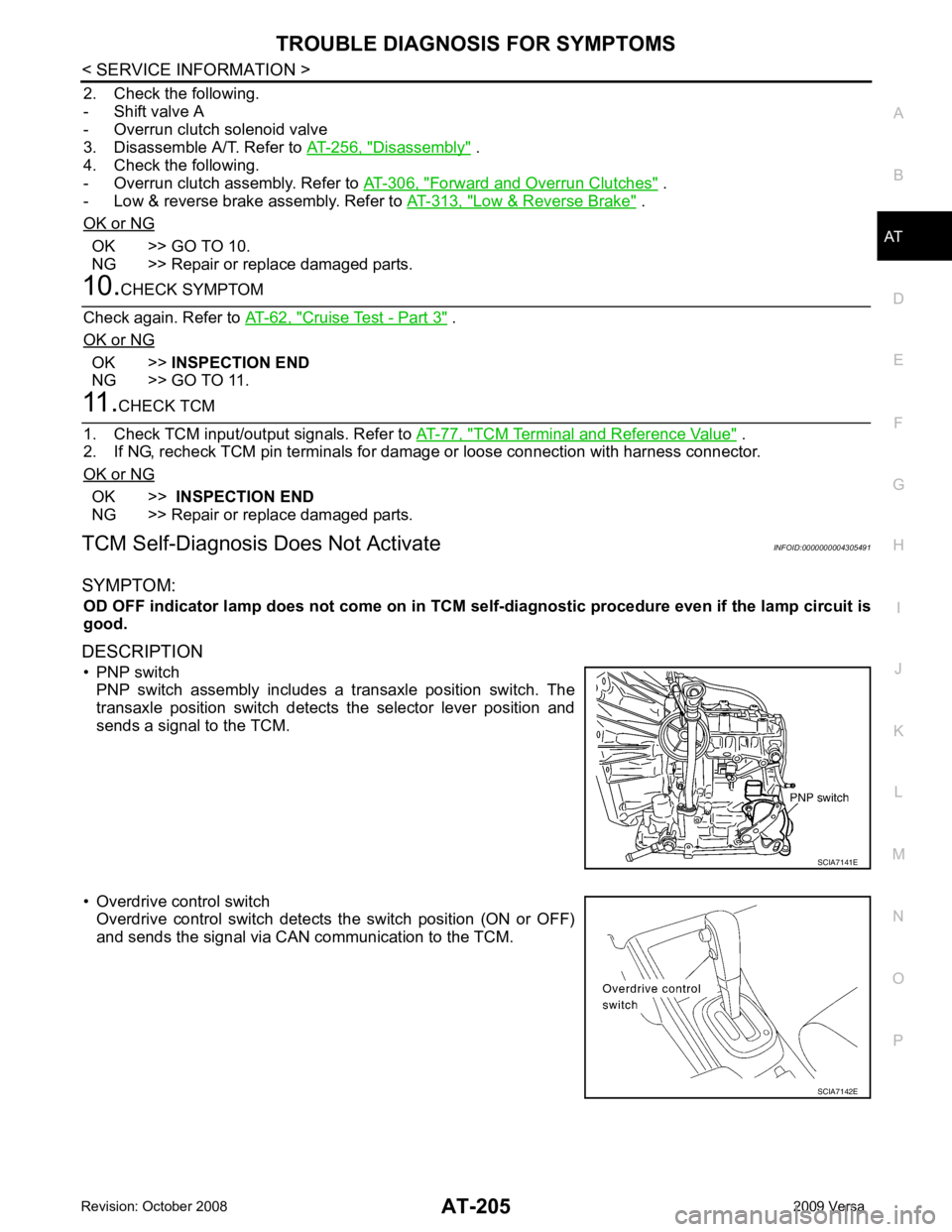
DESCRIPTION • PNP switch PNP switch assembly includes a transaxle position switch. The
transaxle position switch detects the selector lever position and
sends a signal to the TCM.
• Overdrive control switch Overdrive control switch detects the switch position (ON or OFF)
and sends the signal via CAN communication to the TCM.
Page 226 of 4331

AT
N
O P
ON-VEHICLE SERVICE
Control Valve Assembly and Accumulators INFOID:0000000004305503
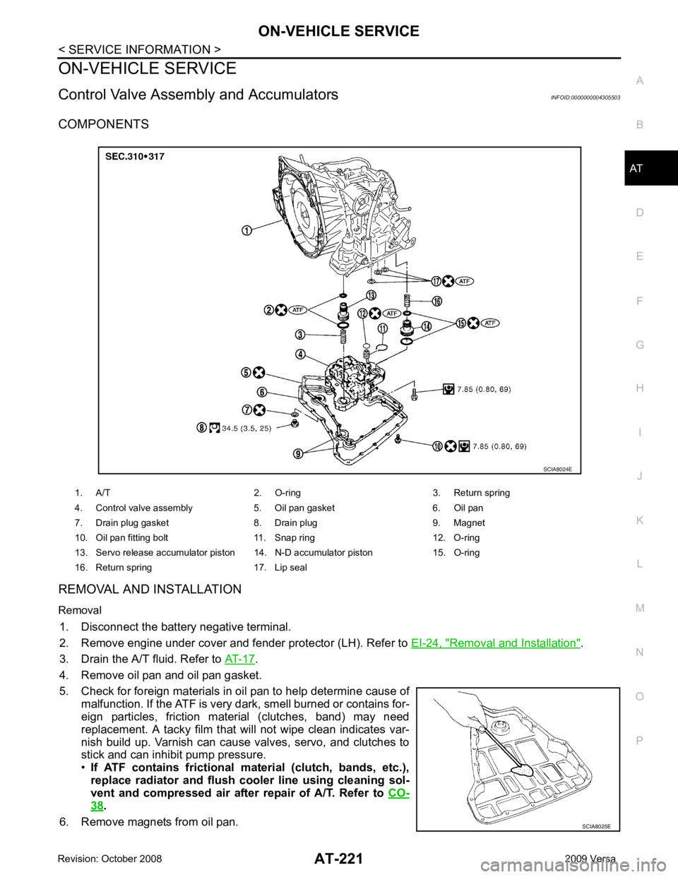
COMPONENTS
REMOVAL AND INSTALLATION
Removal 1. Disconnect the battery negative terminal.
2. Remove engine under cover and fender protector (LH). Refer to EI-24, " Removal and Installation " .
3. Drain the A/T fluid. Refer to AT-17 .
4. Remove oil pan and oil pan gasket.
5. Check for foreign materials in oil pan to help determine cause of malfunction. If the ATF is very dark, smell burned or contains for-
eign particles, friction material (clutches, band) may need
replacement. A tacky film that will not wipe clean indicates var-
nish build up. Varnish can cause valves, servo, and clutches to
stick and can inhibit pump pressure.
• If ATF contains frictional material (clutch, bands, etc.),
replace radiator and flush cooler line using cleaning sol-
vent and compressed air after repair of A/T. Refer to CO-38 .
6. Remove magnets from oil pan. 1. A/T 2. O-ring 3. Return spring
4. Control valve assembly 5. Oil pan gasket 6. Oil pan
7. Drain plug gasket 8. Drain plug 9. Magnet
10. Oil pan fitting bolt 11. Snap ring 12. O-ring
13. Servo release accumulator piston 14. N-D accumulator piston 15. O-ring
16. Return spring 17. Lip seal SCIA8025E
Page 244 of 4331
AT
N
O P
19. Clip 20. O-ring 21. O-ring
22. Oil pump housing oil seal 23. Oil pump housing 24. Outer gear
25. Inner gear 26. Oil pump cover 27. Seal ring
28. Oil pump assembly
1. Retaining plate 2. Driven plate 3. Dish plate
4. Snap ring 5. Spring retainer assembly 6. Reverse clutch piston
Page 252 of 4331

AT
N
O P
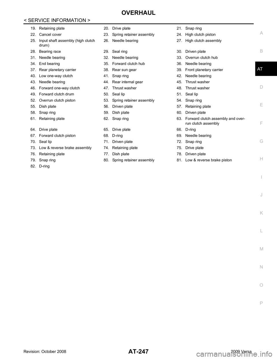
19. Retaining plate 20. Drive plate 21. Snap ring
22. Cancel cover 23. Spring retainer assembly 24. High clutch piston
25. Input shaft assembly (high clutch drum) 26. Needle bearing 27. High clutch assembly
28. Bearing race 29. Seal ring 30. Driven plate
31. Needle bearing 32. Needle bearing 33. Overrun clutch hub
34. End bearing 35. Forward clutch hub 36. Needle bearing
37. Rear planetary carrier 38. Rear sun gear 39. Front planetary carrier
40. Low one-way clutch 41. Snap ring 42. Needle bearing
43. Needle bearing 44. Rear internal gear 45. Thrust washer
46. Forward one-way clutch 47. Thrust washer 48. Thrust washer
49. Forward clutch drum 50. Seal lip 51. Seal lip
52. Overrun clutch piston 53. Spring retainer assembly 54. Snap ring
55. Dish plate 56. Driven plate 57. Retaining plate
58. Snap ring 59. Dish plate 60. Driven plate
61. Retaining plate 62. Snap ring 63. Forward clutch assembly and over- run clutch assembly
64. Drive plate 65. Drive plate 66. D-ring
67. Forward clutch piston 68. D-ring 69. Needle bearing
70. Seal lip 71. Driven plate 72. Snap ring
73. Low & reverse brake assembly 74. Retaining plate 75. Drive plate
76. Retaining plate 77. Dish plate 78. Driven plate
79. Snap ring 80. Spring retainer assembly 81. Low & reverse brake piston
82. D-ring
Page 268 of 4331
AT
N
O P
a. Remove O-ring from input shaft assembly (high clutch drum).
b. Remove oil pump assembly bolts, and then remove oil pump assembly (1) from transaxle case.
c. Remove O-ring from oil pump assembly (1).
d. Remove bearing race (1) and thrust washer (2) from oil pump assembly (3).
30. Remove brake band according to the following procedures.
a. Loosen lock nut (1), and then remove anchor end pin (2) and lock nut (1) as a set from transaxle case.
Page 270 of 4331
AT
N
O P
b. Remove input shaft assembly (high clutch assembly) (1) from
reverse clutch assembly (2).
c. Remove needle bearing (1) from input shaft assembly (high clutch drum) (2).
• Inspect needle bearing (1) and input shaft assembly (high
clutch drum) (2), and replace if damaged or worn.
32. Remove needle bearing from high clutch hub. •Inspect needle bearing, and replace if damaged or worn.
33. Remove high clutch hub from front sun gear. •Inspect high clutch hub, and replace if damaged or worn.
34. Remove needle bearing from front sun gear. •Inspect needle bearing, and replace if damaged or worn. SCIA6959E
SAT371D
SAT369D
Page 272 of 4331
AT
N
O P
c. Check that low one-way clutch rotates counter-clockwise around
front planetary carrier. Then try to turn it clockwise and check
that it is locked.
• Replace low one-way clutch if necessary.
d. Remove low one-way clutch from front planetary carrier by turn- ing it in the direction of unlock.
• Inspect low one-way clutch , and replace if damaged or
worn.
e. Remove needle bearing (1) from front planetary carrier (2). •Inspect needle bearing (1) a nd front planetary carrier (2),
and replace if damaged or worn.
f. Check clearance between pinion washer and front planetary carrier using feeler gauge.
• Replace front planetary carrier if the clearance exceeds
allowable limit.
38. Remove rear planetary carrier and rear sun gear according to the following procedures.
a. Remove rear planetary carrier (with rear sun gear) from tran- saxle case. SCIA6047J
Planetary Carrier " .
SAT051D
Page 274 of 4331
AT
N
O P
41. Remove overrun clutch hub (1
) from forward clutch drum.
42. Remove thrust washer (1) from overrun clutch hub (2). •Inspect thrust washer (1) and overrun clutch hub (2), and
replace if damaged or worn.
43. Remove forward clutch assembly and overrun clutch assembly (1) from transaxle case.
44. Remove needle bearing (1) and thrust washer (2) from bearing retainer.
• Inspect needle bearing (1) an d thrust washer (2), and
replace damaged or worn.
45. Remove output shaft assembly according to the following procedures.
a. HR16DE engine models. SCIA5900J