2009 NISSAN LATIO warning
[x] Cancel search: warningPage 694 of 4331
VEHICLE SECURITY (THEFT WARNING) SYSTEM
BL-233
< SERVICE INFORMATION >
C
D E
F
G H
J
K L
M A
B BL
N
O P
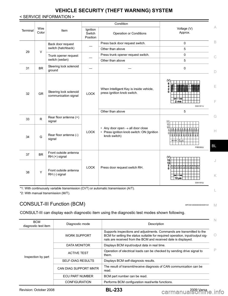
*1: With continuously variable transmission (CVT) or automatic transmission (A/T).
*2: With manual transmission (M/T).
CONSULT-III Function (BCM) INFOID:0000000004305122
CONSULT-III can display each diagnostic item using the diagnostic test modes shown following. 29 V
Back door request
switch (hatchback) —Press back door request switch. 0
Other than above 5
Trunk opener request
switch (sedan) —Press trunk opener request switch. 0
Other than above 5
31 BR Steering lock solenoid
ground — — 0
32 GR Steering lock solenoid
communication signal LOCKWhen Intelligent Key is inside vehicle,
press ignition knob switch.
Other than above 5
33 R Rear floor antenna (+)
signal
LOCK• Any door open
→ all door close
• Press ignition knob switch: ON (Ignition
knob switch)
34 G Rear floor antenna (-)
signal
37 BR Front outside antenna
RH (+) signal
LOCK Press door request switch RH.
38 Y Front outside antenna
RH (-) signal
Terminal
Wire
Color Item Condition
Voltage (V)Approx.
Ignition
Switch
Position Operation or Conditions SIIA1911J
PIIB5502J
SIIA1910J
BCM
diagnostic test item Diagnostic mode Description
Inspection by part WORK SUPPORT
Supports inspections and adjustments. Commands are transmitted to the
BCM for setting the status suitable for required operation, input/output sig-
nals are received from the BCM and received date is displayed.
DATA MONITOR Displays BCM input/output data in real time.
ACTIVE TEST Operation of electrical loads can be checked by sending drive signal to
them.
SELF-DIAG RESULTS Displays BC M self-diagnosis results.
CAN DIAG SUPPORT MNTR The result of transmit/receive diagnosis of CAN communication can be
read.
ECU PART NUMBER BCM part number can be read.
CONFIGURATION Performs BCM configuration read/write functions.
Page 699 of 4331
BL-238< SERVICE INFORMATION >
VEHICLE SECURITY (T
HEFT WARNING) SYSTEM
*1 : Make sure the system is in the armed phase.
Diagnosis Procedure 1 INFOID:0000000004305126
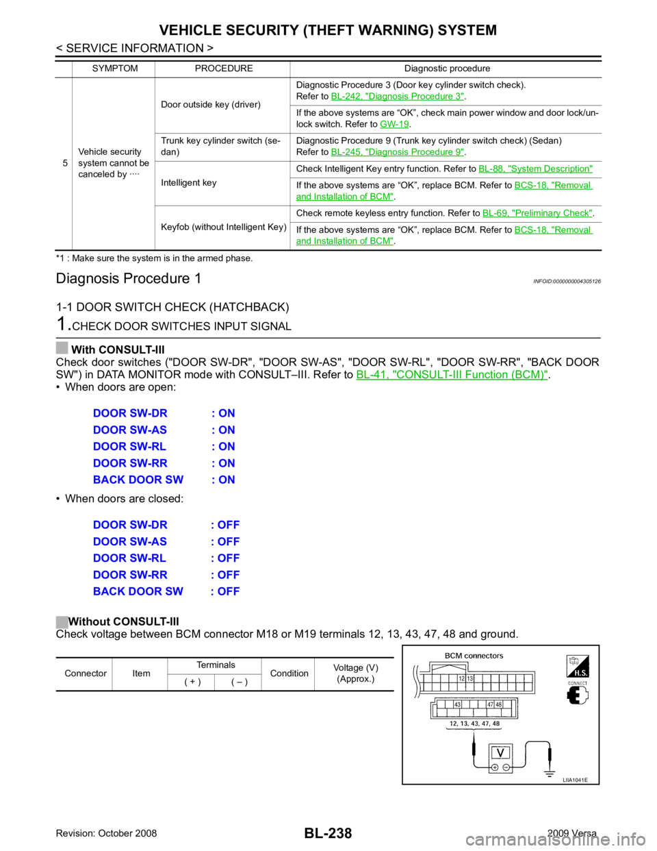
1-1 DOOR SWITCH CHECK (HATCHBACK) 1.
CHECK DOOR SWITCHES INPUT SIGNAL
With CONSULT-III
Check door switches ("DOOR SW-DR", "DOOR SW-AS", "DOOR SW-RL", "DOOR SW-RR", "BACK DOOR
SW") in DATA MONITOR mode with CONSULT–III. Refer to BL-41, " CONSULT-III Function (BCM) " .
• When doors are open:
• When doors are closed:
Without CONSULT-III
Check voltage between BCM connector M18 or M19 terminals 12, 13, 43, 47, 48 and ground.
5
Vehicle security
system cannot be
canceled by ···· Door outside key (driver)
Diagnostic Procedure 3 (Door key cylinder switch check).
Refer to BL-242, " Diagnosis Procedure 3 " .
If the above systems are “OK”, check main power window and door lock/un-
lock switch. Refer to GW-19 .
Trunk key cylinder switch (se-
dan) Diagnostic Procedure 9 (Trunk key cylinder switch check) (Sedan)
Refer to BL-245, " Diagnosis Procedure 9 " .
Intelligent key Check Intelligent Key entry function. Refer to
BL-88, " System Description "
If the above systems are “OK”, replace BCM. Refer to
BCS-18, " Removal
and Installation of BCM " .
Keyfob (without Intelligent Key) Check remote keyless entry function. Refer to
BL-69, " Preliminary Check " .
If the above systems are “OK”, replace BCM. Refer to BCS-18, " Removal
and Installation of BCM " .
SYMPTOM PROCEDURE Diagnostic procedure DOOR SW-DR : ON
DOOR SW-AS : ON
DOOR SW-RL : ON
DOOR SW-RR : ON
BACK DOOR SW : ON
DOOR SW-DR : OFF
DOOR SW-AS : OFF
DOOR SW-RL : OFF
DOOR SW-RR : OFF
BACK DOOR SW : OFF Connector Item
Terminals
ConditionVoltage (V)
(Approx.)
( + ) ( – ) LIIA1041E
Page 701 of 4331
BL-240< SERVICE INFORMATION >
VEHICLE SECURITY (T
HEFT WARNING) SYSTEM
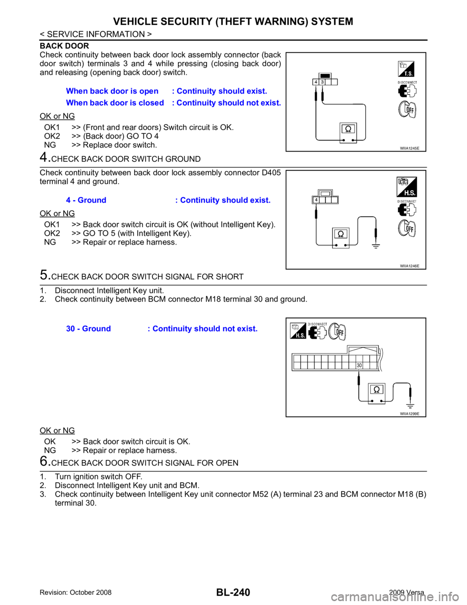
BACK DOOR
Check continuity between back door lock assembly connector (back
door switch) terminals 3 and 4 while pressing (closing back door)
and releasing (opening back door) switch.
OK or NG OK1 >> (Front and rear doors) Switch circuit is OK.
OK2 >> (Back door) GO TO 4
NG >> Replace door switch. 4.
CHECK BACK DOOR SWITCH GROUND
Check continuity between back door lock assembly connector D405
terminal 4 and ground.
OK or NG OK1 >> Back door switch circuit is OK (without Intelligent Key).
OK2 >> GO TO 5 (with Intelligent Key).
NG >> Repair or replace harness. 5.
CHECK BACK DOOR SWITCH SIGNAL FOR SHORT
1. Disconnect Intelligent Key unit.
2. Check continuity between BCM connector M18 terminal 30 and ground.
OK or NG OK >> Back door switch circuit is OK.
NG >> Repair or replace harness. 6.
CHECK BACK DOOR SWITCH SIGNAL FOR OPEN
1. Turn ignition switch OFF.
2. Disconnect Intelligent Key unit and BCM.
3. Check continuity between Intelligent Key unit c onnector M52 (A) terminal 23 and BCM connector M18 (B)
terminal 30. When back door is open :
Continuity should exist.
When back door is closed : Co ntinuity should not exist. WIIA1245E
4 - Ground : Continuity should exist.
WIIA1246E
30 - Ground : Continuity should not exist.
WIIA1299E
Page 704 of 4331
VEHICLE SECURITY (THEFT WARNING) SYSTEM
BL-243
< SERVICE INFORMATION >
C
D E
F
G H
J
K L
M A
B BL
N
O P 1.
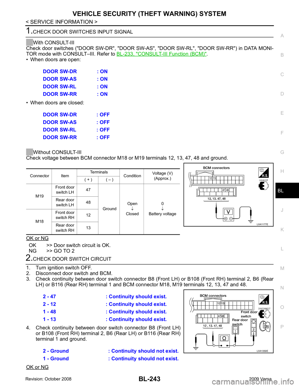
CHECK DOOR SWITCHES INPUT SIGNAL
With CONSULT-III
Check door switches ("DOOR SW-DR", "DOOR SW-AS" , "DOOR SW-RL", "DOOR SW-RR") in DATA MONI-
TOR mode with CONSULT–III. Refer to BL-233, " CONSULT-III Function (BCM) " .
• When doors are open:
• When doors are closed:
Without CONSULT-III
Check voltage between BCM connector M18 or M19 terminals 12, 13, 47, 48 and ground.
OK or NG OK >> Door switch circuit is OK.
NG >> GO TO 2 2.
CHECK DOOR SWITCH CIRCUIT
1. Turn ignition switch OFF.
2. Disconnect door switch and BCM.
3. Check continuity between door switch connector B8 (F ront LH) or B108 (Front RH) terminal 2, B6 (Rear
LH) or B116 (Rear RH) terminal 1 and BCM connector M18, M19 terminals 12, 13, 47 and 48.
4. Check continuity between door switch connector B8 (Front LH) or B108 (Front RH) terminal 2, B6 (Rear LH) or B116 (Rear RH)
terminal 1 and ground.
OK or NG DOOR SW-DR : ON
DOOR SW-AS : ON
DOOR SW-RL : ON
DOOR SW-RR : ON
DOOR SW-DR : OFF
DOOR SW-AS : OFF
DOOR SW-RL : OFF
DOOR SW-RR : OFF Connector Item
Terminals
ConditionVoltage (V)
(Approx.)
( + ) ( – )
M19 Front door
switch LH 47
Ground Open
↓
Closed 0
↓
Battery voltage
Rear door
switch LH 48
M18 Front door
switch RH 12
Rear door
switch RH 13 LIIA1177E
2 - 47 : Continuity should exist.
2 - 12 : Continuity should exist.
1 - 48 : Continuity should exist.
1 - 13 : Continuity should exist.
2 - Ground : Continuity should not exist.
1 - Ground : Continuity should not exist. LIIA1350E
Page 705 of 4331
BL-244< SERVICE INFORMATION >
VEHICLE SECURITY (T
HEFT WARNING) SYSTEM
OK >> GO TO 3
NG >> Repair or replace harness. 3.
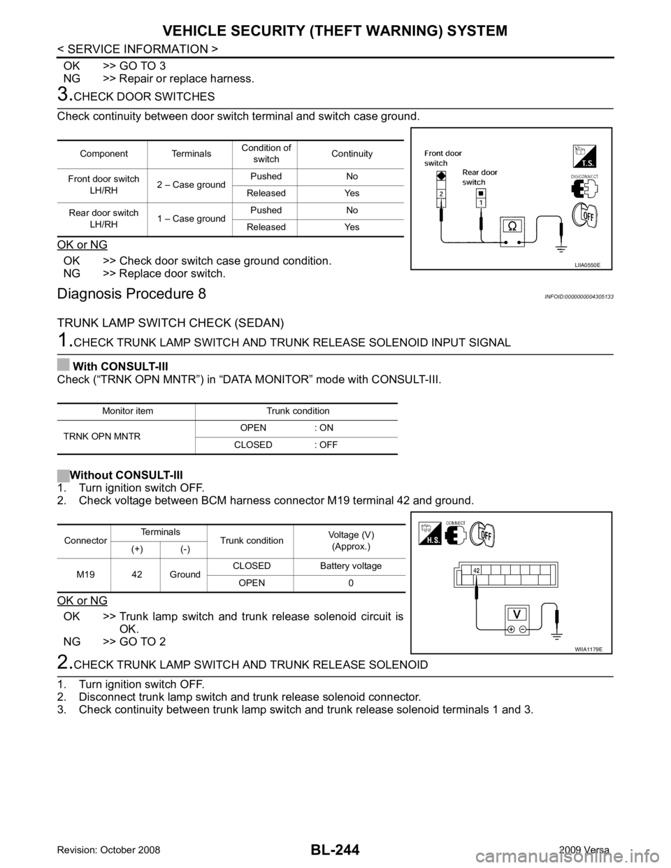
CHECK DOOR SWITCHES
Check continuity between door switch terminal and switch case ground.
OK or NG OK >> Check door switch case ground condition.
NG >> Replace door switch.
Diagnosis Procedure 8 INFOID:0000000004305133
TRUNK LAMP SWITCH CHECK (SEDAN) 1.
CHECK TRUNK LAMP SWITCH AND TRUNK RELEASE SOLENOID INPUT SIGNAL
With CONSULT-III
Check (“TRNK OPN MNTR”) in “DATA MONITOR” mode with CONSULT-III.
Without CONSULT-III
1. Turn ignition switch OFF.
2. Check voltage between BCM harness connector M19 terminal 42 and ground.
OK or NG OK >> Trunk lamp switch and trunk release solenoid circuit is
OK.
NG >> GO TO 2 2.
CHECK TRUNK LAMP SWITCH A ND TRUNK RELEASE SOLENOID
1. Turn ignition switch OFF.
2. Disconnect trunk lamp switch and trunk release solenoid connector.
3. Check continuity between trunk lamp switch and trunk release solenoid terminals 1 and 3.
Component Terminals
Condition of
switch Continuity
Front door switch LH/RH 2 – Case ground Pushed No
Released Yes
Rear door switch LH/RH 1 – Case ground Pushed No
Released Yes LIIA0550E
Monitor item Trunk condition
TRNK OPN MNTR OPEN : ON
CLOSED : OFF Connector
Terminals
Trunk condition Voltage (V)
(Approx.)
(+) (-)
M19 42 Ground CLOSED Battery voltage
OPEN 0 WIIA1179E
Page 713 of 4331
BL-252< SERVICE INFORMATION >
NATS (NISSAN ANTI-THEFT SYSTEM)
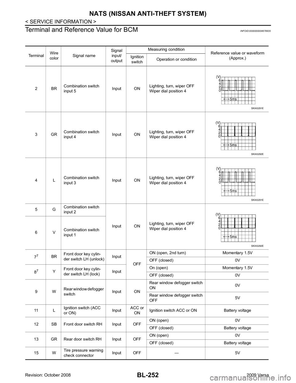
Terminal and Reference Value for BCM INFOID:0000000004678935
Terminal Wire
color Signal name Signal
input/
output Measuring condition
Reference value or waveform
(Approx.)
Ignition
switch Operation or condition
2 BR Combination switch
input 5 Input ONLighting, turn, wiper OFF
Wiper dial position 4
3 GR Combination switch
input 4 Input ONLighting, turn, wiper OFF
Wiper dial position 4
4 L Combination switch
input 3 Input ONLighting, turn, wiper OFF
Wiper dial position 4
5 G Combination switch
input 2
Input ONLighting, turn, wiper OFF
Wiper dial position 4
6 V Combination switch
input 1
7 7
BRFront door key cylin-
der switch LH (unlock) Input
OFFON (open, 2nd turn) Momentary 1.5V
OFF (closed) 0V
8 7
YFront door key cylin-
der switch LH (lock) InputOn (open) Momentary 1.5V
OFF (closed) 0V
9 W Rear window defogger
switch Input ONRear window defogger switch
ON 0V
Rear window defogger switch
OFF 5V
11 L Ignition switch (ACC
or ON) InputACC or
ON Ignition switch ACC or ON Battery voltage
12 SB Front door switch RH Input OFF ON (open) 0V
OFF (closed) Ba ttery voltage
13 GR Rear door switch RH Input OFF ON (open) 0V
OFF (closed) Ba ttery voltage
15 W Tire pressure warning
check connector Input OFF — 5V SKIA5291E
SKIA5292E
SKIA5291E
SKIA5292E
Page 718 of 4331
BL
N
O P
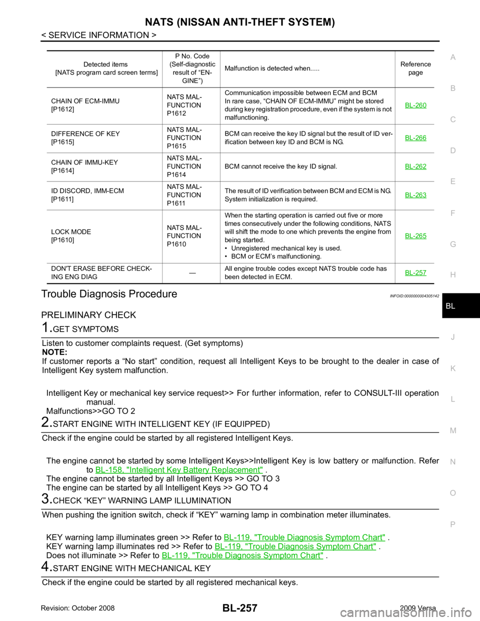
Trouble Diagnosis Procedure
INFOID:0000000004305142
PRELIMINARY CHECK Intelligent Key Battery Replacement " .
The engine cannot be started by all Intelligent Keys >> GO TO 3
The engine can be started by all Intelligent Keys >> GO TO 4 Trouble Diagnosis Symptom Chart " .
KEY warning lamp illuminates red >> Refer to BL-119, " Trouble Diagnosis Symptom Chart " .
Does not illuminate >> Refer to BL-119, " Trouble Diagnosis Symptom Chart " .DIFFERENCE OF KEY
[P1615] NATS MAL-
FUNCTION
P1615 BCM can receive the key ID signal but the result of ID ver-
ification between key ID and BCM is NG. BL-266CHAIN OF IMMU-KEY
[P1614] NATS MAL-
FUNCTION
P1614 BCM cannot receive the key ID signal.
BL-262ID DISCORD, IMM-ECM
[P1611] NATS MAL-
FUNCTION
P1611 The result of ID verification between BCM and ECM is NG.
System initialization is required. BL-263LOCK MODE
[P1610] NATS MAL-
FUNCTION
P1610 When the starting operation is carried out five or more
times consecutively under the following conditions, NATS
will shift the mode to one which prevents the engine from
being started.
• Unregistered mechanical key is used.
• BCM or ECM’s malfunctioning. BL-265DON'T ERASE BEFORE CHECK-
ING ENG DIAG —All engine trouble codes except NATS trouble code has
been detected in ECM. BL-257
Page 809 of 4331
BR
N
O P
BRAKE FLUID
On Board Inspection INFOID:0000000004305892
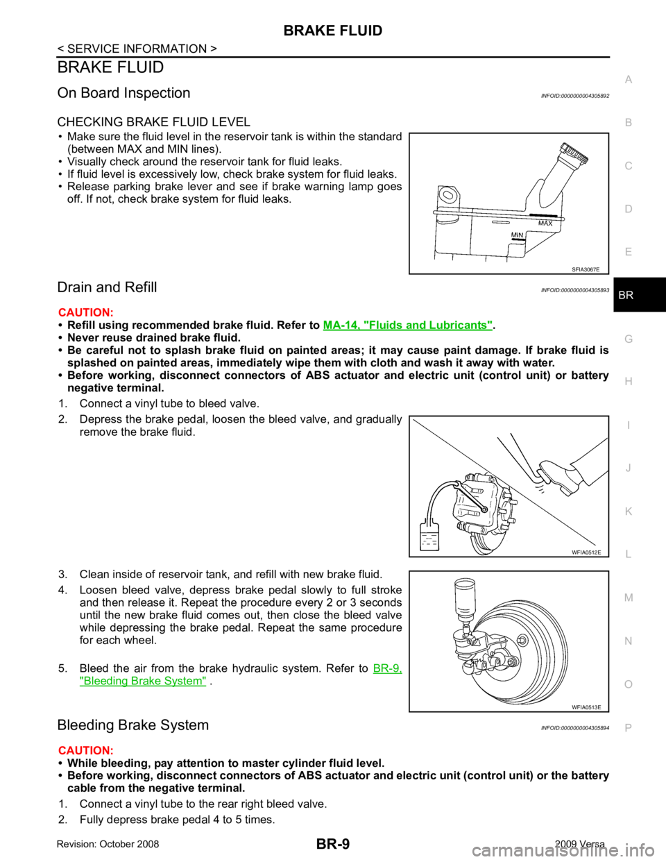
CHECKING BRAKE FLUID LEVEL • Make sure the fluid level in the reservoir tank is within the standard (between MAX and MIN lines).
• Visually check around the reservoir tank for fluid leaks.
• If fluid level is excessively low, check brake system for fluid leaks.
• Release parking brake lever and see if brake warning lamp goes
off. If not, check brake system for fluid leaks.
Drain and Refill INFOID:0000000004305893
CAUTION:
• Refill using recommended brake fluid. Refer to MA-14, " Fluids and Lubricants " .
• Never reuse drained brake fluid.
• Be careful not to splash brake fluid on painted areas; it may cause paint damage. If brake fluid is
splashed on painted areas, immediately wipe th em with cloth and wash it away with water.
• Before working, disconnect connect ors of ABS actuator and electric unit (control unit) or battery
negative terminal.
1. Connect a vinyl tube to bleed valve.
2. Depress the brake pedal, loosen the bleed valve, and gradually remove the brake fluid.
3. Clean inside of reservoir tank, and refill with new brake fluid.
4. Loosen bleed valve, depress brake pedal slowly to full stroke and then release it. Repeat the procedure every 2 or 3 seconds
until the new brake fluid comes out, then close the bleed valve
while depressing the brake pedal . Repeat the same procedure
for each wheel.
5. Bleed the air from the brake hydraulic system. Refer to BR-9," Bleeding Brake System " .
Bleeding Brake System INFOID:0000000004305894
CAUTION:
• While bleeding, pay attention to master cylinder fluid level.
• Before working, disconnect connectors of ABS actuator and electri c unit (control unit) or the battery
cable from the negative terminal.
1. Connect a vinyl tube to the rear right bleed valve.
2. Fully depress brake pedal 4 to 5 times.