Page 587 of 4331
![NISSAN LATIO 2009 Service Repair Manual NO DTC IS DETECT
ED>> Inspection End.
CAN COMM [U1000]>> After printing “SELF-DIAGNOSI S RESULTS”, go to “CAN SYSTEM”. Refer to LAN-17, " Trouble Diagnosis Flow Chart " .
CAN COMM2 [U1010] >> NISSAN LATIO 2009 Service Repair Manual NO DTC IS DETECT
ED>> Inspection End.
CAN COMM [U1000]>> After printing “SELF-DIAGNOSI S RESULTS”, go to “CAN SYSTEM”. Refer to LAN-17, " Trouble Diagnosis Flow Chart " .
CAN COMM2 [U1010] >>](/manual-img/5/57359/w960_57359-586.png)
NO DTC IS DETECT
ED>> Inspection End.
CAN COMM [U1000]>> After printing “SELF-DIAGNOSI S RESULTS”, go to “CAN SYSTEM”. Refer to LAN-17, " Trouble Diagnosis Flow Chart " .
CAN COMM2 [U1010] >> Replace Intelligent Key unit. Refer to BL-158, " Removal and Installation of Intelli-
gent Key Unit " .
Power Supply and Ground Circuit Inspection INFOID:00000000043050462. Check Intelligent Key battery.
BL-158 3. Check KEY warning lamp (green).
BL-155 4. Replace Intelligent Key unit.
BL-158P position warning lamp does not illuminate properly.
(With CVT or A/T) 1. Check CVT or A/T device (park position switch).
BL-153 2. Check “P-SHIFT” warning lamp (red).
BL-154 3. Replace Intelligent Key unit.
BL-158LOCK warning lamp does not illuminate properly.
(With M/T) 1. Check key interlock solenoid.
BL-149 2. Check "LOCK" warning lamp.
BL-155 3. Replace Intelligent Key unit.
BL-158Take away warning lamp does not illuminate properly.
(Take away warning chime is operated). 1. Check KEY warning lamp (red).
BL-158 2. Replace Intelligent Key unit.
BL-158Ignition switch warning lamp does not illuminate properly.
(Ignition switch warning chime is operated). 1. Check KEY warning lamp (red).
BL-155 2. Replace Intelligent Key unit.
BL-158CONSULT-III display item DTC code
NO DTC IS DETECTED — CAN COMM U1000
CAN COMM2 U1010
Page 603 of 4331

BL-142< SERVICE INFORMATION >
INTELLIGENT KEY SYSTEM
OK or NG OK >> Replace front door lock actuator LH (door unlock sen-
sor). Refer to BL-166, " Removal and Installation " .
NG >> Replace Intelligent Key unit. Refer to BL-158, " Removal
and Installation of Intelligent Key Unit " .
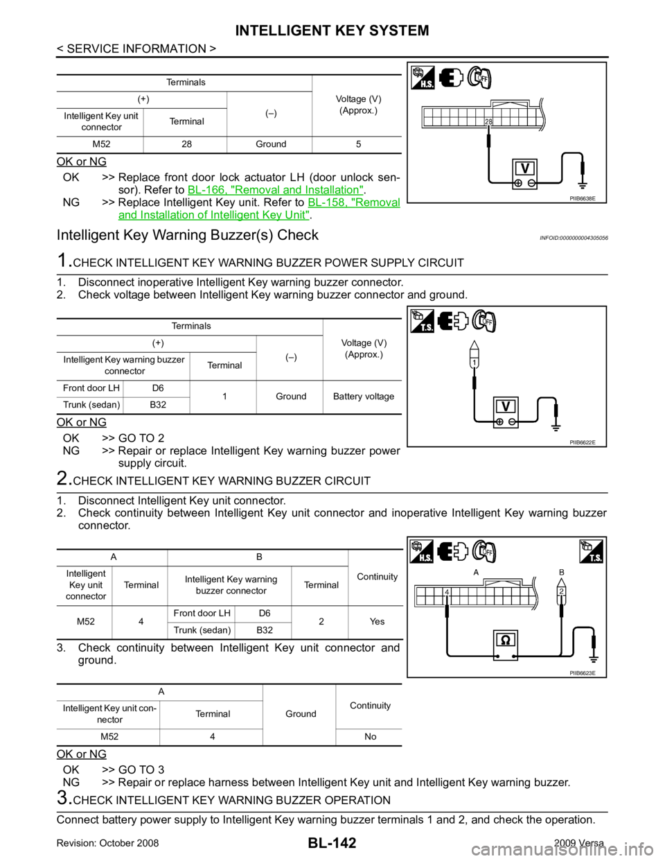
Intelligent Key Warning Buzzer(s) Check INFOID:00000000043050561.
CHECK INTELLIGENT KEY WARNING BUZZER POWER SUPPLY CIRCUIT
1. Disconnect inoperative Intelligent Key warning buzzer connector.
2. Check voltage between Intelligent Key warning buzzer connector and ground.
OK or NG OK >> GO TO 2
NG >> Repair or replace Intelligent Key warning buzzer power supply circuit. 2.
CHECK INTELLIGENT KEY WARNING BUZZER CIRCUIT
1. Disconnect Intelligent Key unit connector.
2. Check continuity between Intelligent Key unit c onnector and inoperative Intelligent Key warning buzzer
connector.
3. Check continuity between Intelligent Key unit connector and ground.
OK or NG OK >> GO TO 3
NG >> Repair or replace harness between Intelligent Key unit and Intelligent Key warning buzzer. 3.
CHECK INTELLIGENT KEY WA RNING BUZZER OPERATION
Connect battery power supply to Intelligent Key warning buzzer terminals 1 and 2, and check the operation. Terminals
Voltage (V)(Approx.)
(+)
(–)
Intelligent Key unit
connector Terminal
M52 28 Ground 5 PIIB6638E
Terminals
Voltage (V)(Approx.)
(+)
(–)
Intelligent Key warning buzzer
connector Terminal
Front door LH D6 1 Ground Battery voltage
Trunk (sedan) B32 PIIB6622E
A B
Continuity
Intelligent
Key unit
connector Terminal
Intelligent Key warning
buzzer connector Terminal
M52 4 Front door LH D6
2 Yes
Trunk (sedan) B32
A GroundContinuity
Intelligent Key unit con-
nector Terminal
M52 4 No PIIB6623E
Page 604 of 4331
BL
N
O P
OK or NG OK >> Intelligent Key warning buzzer is OK.
NG >> Replace inoperative Intelligent Key warning buzzer.
Outside Key Antenna (Driver Si de and Passenger Side) Check INFOID:0000000004305057Yes >> Outside key antenna (driver side or passenger side) is OK.
No >> GO TO 2 OK >> Outside key antenna is OK.
NG >> GO TO 3 SIIA1910J
Page 615 of 4331
OK >> GO TO 5
NG >> Repair or replace harness. OK >> CVT or A/T device (park position switch) circuit is OK.
NG >> Replace Intelligent Key unit. Refer to BL-158, " Removal
and Installation of Intelligent Key Unit " .
"P-SHIFT" Warning Lamp (With CVT or A/T) Check INFOID:0000000004305066OK >> Inspection End.
NG >> Check combination meter. Refer to DI-3 .
10 – 8 : Continuity should exist.
10 – Ground : Continuity should not exist. WIIA1262E
Page 616 of 4331
BL
N
O P
"LOCK" Warning Lamp (With M/T) Check
INFOID:0000000004305067OK >> Inspection End.
NG >> Check combination meter. Refer to DI-3 .
"KEY" Warning Lamp (RED) Check INFOID:0000000004305068OK >> Inspection End.
NG >> Check combination meter. Refer to DI-3 .
"KEY" Warning Lamp (GREEN) Check INFOID:0000000004305069 WIIA1264E
Page 617 of 4331
OK >> Inspection End.
NG >> Check combination meter. Refer to DI-3 .
Check Warning Chime in Combination Meter INFOID:0000000004305070OK >> Inspection End.
NG >> GO TO 2. OK >> Inspection End.
NG >> Refer to DI-42 .
Hazard Function Check INFOID:0000000004305071YES >> Hazard warning lamp circuit is OK.
NO >> Check hazard circuit. Refer to LT-48 .Does warning chime in combination meter sound?
Page 636 of 4331

BACK DOOR LOCK
BL-175
< SERVICE INFORMATION >
C
D E
F
G H
J
K L
M A
B BL
N
O P
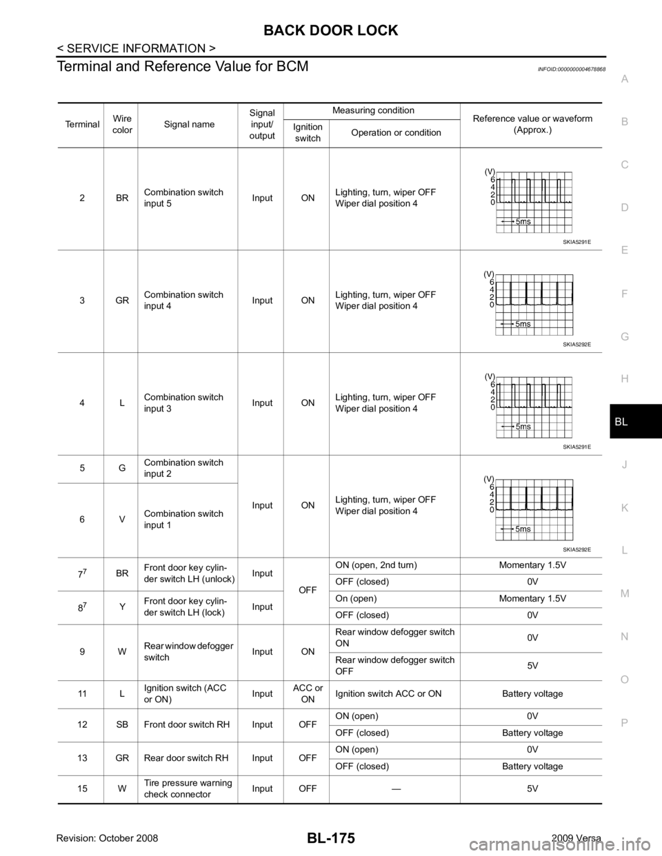
Terminal and Reference Value for BCM
INFOID:0000000004678868
Terminal Wire
color Signal name Signal
input/
output Measuring condition
Reference value or waveform
(Approx.)
Ignition
switch Operation or condition
2 BR Combination switch
input 5 Input ONLighting, turn, wiper OFF
Wiper dial position 4
3 GR Combination switch
input 4 Input ONLighting, turn, wiper OFF
Wiper dial position 4
4 L Combination switch
input 3 Input ONLighting, turn, wiper OFF
Wiper dial position 4
5 G Combination switch
input 2
Input ONLighting, turn, wiper OFF
Wiper dial position 4
6 V Combination switch
input 1
7 7
BRFront door key cylin-
der switch LH (unlock) Input
OFFON (open, 2nd turn) Momentary 1.5V
OFF (closed) 0V
8 7
YFront door key cylin-
der switch LH (lock) InputOn (open) Momentary 1.5V
OFF (closed) 0V
9 W Rear window defogger
switch Input ONRear window defogger switch
ON 0V
Rear window defogger switch
OFF 5V
11 L Ignition switch (ACC
or ON) InputACC or
ON Ignition switch ACC or ON Battery voltage
12 SB Front door switch RH Input OFF ON (open) 0V
OFF (closed) Battery voltage
13 GR Rear door switch RH Input OFF ON (open) 0V
OFF (closed) Battery voltage
15 W Tire pressure warning
check connector Input OFF — 5V SKIA5291E
SKIA5292E
SKIA5291E
SKIA5292E
Page 640 of 4331

BL
N
O P
1: With Intelligent Key
2: Without Intelligent Key
3: Hatchback without Intelligent Key
4: Sedan without Intelligent Key
5: Hatchback
6: Sedan
7: With power door locks
8: With power windows
Terminal and Reference Valu e for Intelligent Key Unit INFOID:0000000004678879
65
7
SBAll door lock actuators
(lock) Output OFFOFF (neutral) 0V
ON (lock) Battery voltage
66 7
GFront door lock actua-
tor RH, rear door lock
actuators LH/RH (un-
lock) Output OFFOFF (neutral) 0V
ON (unlock) Battery voltage
67 B Ground Input ON — 0V
68 8
LPower window power
supply (RAP) Output —Ignition switch ON Battery voltage
Within 45 seconds after igni-
tion switch OFF Battery voltage
More than 45 seconds after ig-
nition switch OFF 0V
When front door LH or RH is
open or power window timer
operates 0V
69 8
P Battery power supply
OutputOFF
— Battery voltage
70 Y Battery power supply Input OFF — Battery voltage
Terminal
Wire
color Signal name Signal
input/
output Measuring condition
Reference value or waveform
(Approx.)
Ignition
switch Operation or condition Terminal
Wire
Color Item Condition
Voltage (V)Approx.
Ignition
Switch
Position Operation or Conditions
1 R Steering lock solenoid
power supply LOCK — 5
2 L CAN-H — — —
3 P CAN-L — — —
4 O Intelligent Key warning
buzzer LOCKOperate door request
switch. Buzzer OFF Battery voltage
Sound buzzer 0
5 G Front door request
switch LH —Press door request switch (driver side). 0
Other than above 5
6 Y Ignition switch (ON) ON — Battery voltage
7 LG Key switch LOCK Insert mechanical key into ignition switch. Battery voltage
Remove mechanical key from ignition
switch. 0
10 *1
WCVT or A/T device
(park position switch) ONShift lever in park position. 0
Other than above Battery voltage
11 SB Power source (Fus e) — — Battery voltage
12 B Ground — — 0