Page 3947 of 4331
Component Parts " .
2. Remove side ventilator duct (right). Refer to MTC-69, " Removal and Installation " .
3. Disconnect blower motor connector (1).
4. Push the flange holding hook (A) toward the blower motor (2), then rotate the blower motor (2) clockwise and remove it from
the A/C unit assembly.
CAUTION:
When blower fan and blower motor are assembled, the bal-
ance is adjusted, do not di sassemble to replace the individ-
ual parts.
INSTALLATION
Installation is in the reverse order of removal.
CAUTION:
Rotate the blower motor until the blower motor fl ange holding hook locks securely into the A/C unit
assembly.
Page 3949 of 4331
.
2. Remove outer cable of air mix door cable (1) from clamp (A).
3. Set temperature control dial to full cold position.
4. Push air mix door lever (2) in the direction shown by arrow, and then carefully pull outer cable toward controller side, and install
clamp (A).
5. Operate temperature control dial to insure that inner cable moves smoothly.
CAUTION:
When clamping the outer cable, do not move the inner
cable.
Page 3969 of 4331

Removal and Installation " .
3. Remove high-pressure flexible hose and high-pressure pipe from condenser. Refer to MTC-82, " Removal
and Installation of High-Pressure Flexible Hose " and
MTC-83, " Removal and Installation of High-Pressure
Pipe " .
CAUTION:
Cap or wrap the joint of the pipe with suitable ma terial such as vinyl tape to avoid the entry of air.
4. Disconnect refrigerant pressure sensor connector.
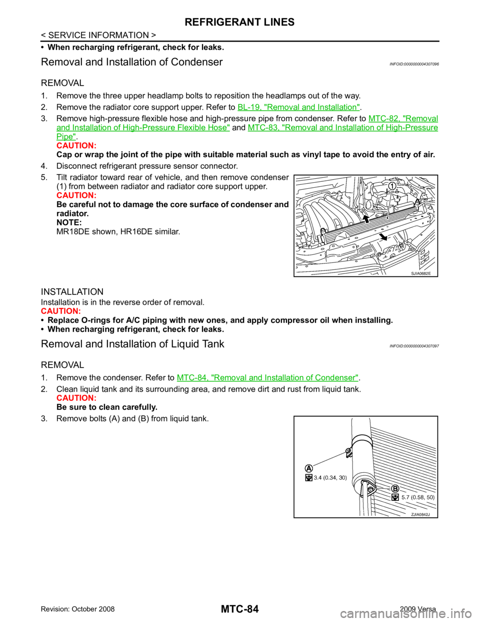
5. Tilt radiator toward rear of vehicle, and then remove condenser (1) from between radiator and radiator core support upper.
CAUTION:
Be careful not to damage the core surface of condenser and
radiator.
NOTE:
MR18DE shown, HR16DE similar.
INSTALLATION
Installation is in the reverse order of removal.
CAUTION:
• Replace O-rings for A/C piping with new ones, and apply compressor oil when installing.
• When recharging refrigerant, check for leaks.
Removal and Installation of Liquid Tank INFOID:0000000004307097
REMOVAL
1. Remove the condenser. Refer to MTC-84, " Removal and Installation of Condenser " .
2. Clean liquid tank and its surrounding area, and remove dirt and rust from liquid tank. CAUTION:
Be sure to clean carefully.
3. Remove bolts (A) and (B) from liquid tank. ZJIA0842J
Page 4059 of 4331
PS
N
O P
- Before disassembly, thoroughly clean the outside of the unit.
- Disassembly should be done in a clean work area. It is im portant to prevent the internal parts from becoming
contaminated by dirt or other foreign matter.
- For easier and proper assembly, place disassembled parts in order on a parts rack.
- Use nylon cloth or paper towels to clean the parts; common shop rags can leave lint that might interfere with
their operation.
- Do not reuse non-reusable parts.
- Before assembling, apply the specif ied grease to the directed parts.
Page 4094 of 4331

RF
N
O P
• the sunroof motor is removed from the sunroof
assembly and the glass panel position is changed.
RE-TEACHING PROCEDURE 1. Using the UP/CLOSE switch, move the sunroo f toward the tilt position until it stops.
2. Release the UP/CLOSE switch.
3. Press the UP/CLOSE switch again and continuously hold. The sunroof will begin to move in about 10 sec- onds.
4. Continue to hold the UP/CLOSE switch while the sunroof moves in a jogging motion to the full tilt position.
When the sunroof reaches the full tilt positi on, it will back up a few millimeters and stop.
5. Release the UP/CLOSE switch.
6. Within 5 seconds of releasing the UP/CLOSE s witch, press and hold the UP/CLOSE switch again. The
sunroof will move to the full open pos ition and back to the closed position.
NOTE:
If the UP/CLOSE switch is released anytime during th is teaching process, all learned profile data will be dis-
carded and the procedure will have to be started over.
7. Release the UP/CLOSE switch. Do not disconnect power for at least two seconds. The sunroof is now re-
taught.
CAN Communication System Description INFOID:0000000004307395
Refer to LAN-8 .
Page 4187 of 4331
SE-24< SERVICE INFORMATION >
REAR SEAT
NOTE:
Confirm that side hinge bracket location pin is set to the hole on the seatback backside.
Disassembly and Assembly INFOID:0000000004306516
60:40 SPLIT FOLD DOWN SEAT - SEDAN
Disassembly of Armrest
1. Fold down the armrest and remove the armrest bolt cover (A).
2. Remove the armrest bolt (A).
3. Push the armrest toward left side while pulling backward to remove.
4. Remove the rear seat bushing, and then remove the armrest hinge cover by pulling it backward.
Assembly of Armrest
Assembly is in the reverse order of disassembly. WIIA1384E
WIIA1385E
PIIB2915J
PIIB6507E
Page 4228 of 4331

SRS-38< ON-VEHICLE REPAIR >
SPIRAL CABLE
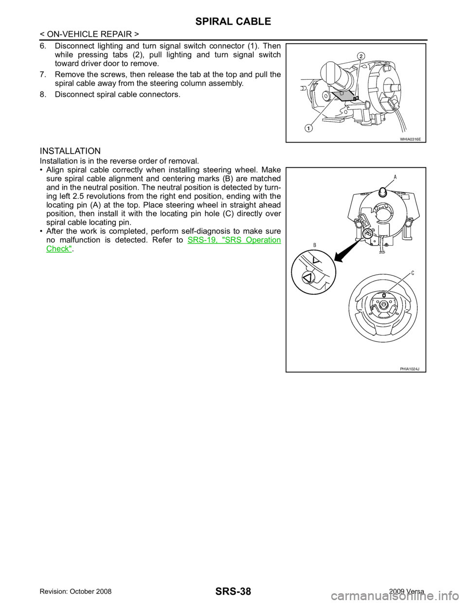
6. Disconnect lighting and turn signal switch connector (1). Then while pressing tabs (2), pull lighting and turn signal switch
toward driver door to remove.
7. Remove the screws, then release the tab at the top and pull the spiral cable away from the steering column assembly.
8. Disconnect spiral cable connectors.
INSTALLATION
Installation is in the reverse order of removal.
• Align spiral cable correctly when installing steering wheel. Make sure spiral cable alignment and centering marks (B) are matched
and in the neutral position. The neutra l position is detected by turn-
ing left 2.5 revolutions from the right end position, ending with the
locating pin (A) at the top. Place steering wheel in straight ahead
position, then install it with the locating pin hole (C) directly over
spiral cable locating pin.
• After the work is completed, perform self-diagnosis to make sure
no malfunction is detected. Refer to SRS-19, " SRS Operation
Check " . WHIA0316E
PHIA1024J
Page 4235 of 4331

SRS
N
O P
DIAGNOSIS SENSOR UNIT
Removal and Installation INFOID:0000000004307202
REMOVAL WARNING:
Before disconnecting diagnosis sensor unit harness connector(s), be sure to disconnect harness con-
nectors from air bag modules and front seat belt pr e-tensioner to prevent deployment by static elec-
tricity.
CAUTION:
• Before servicing the SRS, turn th e ignition switch OFF, disconnect both battery terminals and wait at
least three minutes.
• Do not disassemble di agnosis sensor unit.
• Do not use old bolts; replace with new bolts.
• Replace the diagnosis sensor unit if it has been dropped or sustained an impact.
• Check diagnosis sensor unit bracket to make sure it is free of deformities, dents, cracks or rust. If it
shows any visible signs of da mage, replace with new one.
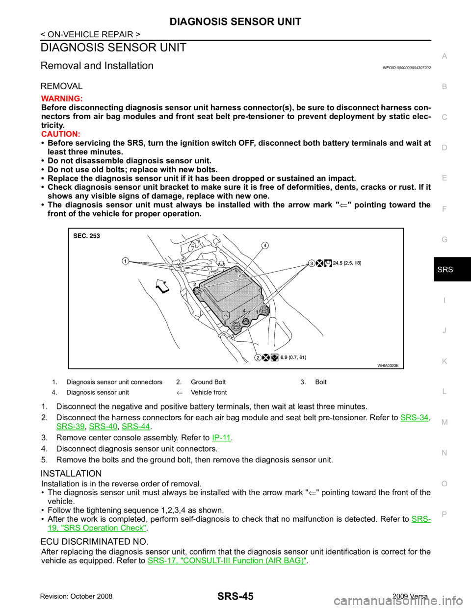
• The diagnosis sensor unit must always be installed with the arrow mark "⇐" pointing toward the
front of the vehicle for proper operation.
1. Disconnect the negative and positive battery term inals, then wait at least three minutes.
2. Disconnect the harness connectors for each air bag module and seat belt pre-tensioner. Refer to SRS-34 ,
SRS-39 ,
SRS-40 ,
SRS-44 .
3. Remove center console assembly. Refer to IP-11 .
4. Disconnect diagnosis sensor unit connectors.
5. Remove the bolts and the ground bolt, then remove the diagnosis sensor unit.
INSTALLATION Installation is in the reverse order of removal.
• The diagnosis sensor unit must always be installed with the arrow mark " ⇐" pointing toward the front of the
vehicle.
• Follow the tightening sequence 1,2,3,4 as shown.
• After the work is completed, perform self-diagnosis to check that no malfunction is detected. Refer to SRS-19, " SRS Operation Check " .
ECU DISCRIMINATED NO. After replacing the diagnosis sensor unit, confirm that t he diagnosis sensor unit identification is correct for the
vehicle as equipped. Refer to SRS-17, " CONSULT-III Function (AIR BAG) " .
1. Diagnosis sensor unit connectors 2. Ground Bolt 3. Bolt
4. Diagnosis sensor unit ⇐Vehicle front