Page 3666 of 4331
.
2. While pressing pawls (A) in direction as shown, pull lighting and turn signal switch (1) toward LH door and disconnect from the
base.
INSTALLATION
Installation is in the reverse order of removal.
Page 3693 of 4331
LT
N
O P
Removal and Installation
INFOID:0000000004306624
HATCHBACK
Removal 1. Remove rear combination lamp nuts.
2. Pull the rear combination lamp toward rear of the vehicle and remove from the vehicle.
3. Disconnect rear combination lamp connector, and remove rear combination lamp.
Installation Installation is in the reverse order of removal.
SEDAN
Removal 1. Remove trunk side finisher. Refer to EI-53, " Removal and Installation " .
2. Remove the rear combination lamp nuts (1).
3. Remove the rear combination lamp (2).
4. Remove the rear combination lamp seal (3).
Installation Installation is in the reverse order of removal.
Disassembly and Assembly INFOID:0000000004306625
DISSASEMBLY 1. Remove the rear combination lamp harness.
2. Remove the bulbs from the rear combination lamp harness, as necessary.
3. Remove the bumper stay (hatchback only).
4. Remove the rear combination lamp seal (sedan only).
ASSEMBLY Assembly is in the reverse order of disassembly.
Page 3752 of 4331
MA
N
O P
PERIODIC MAINTENANCE
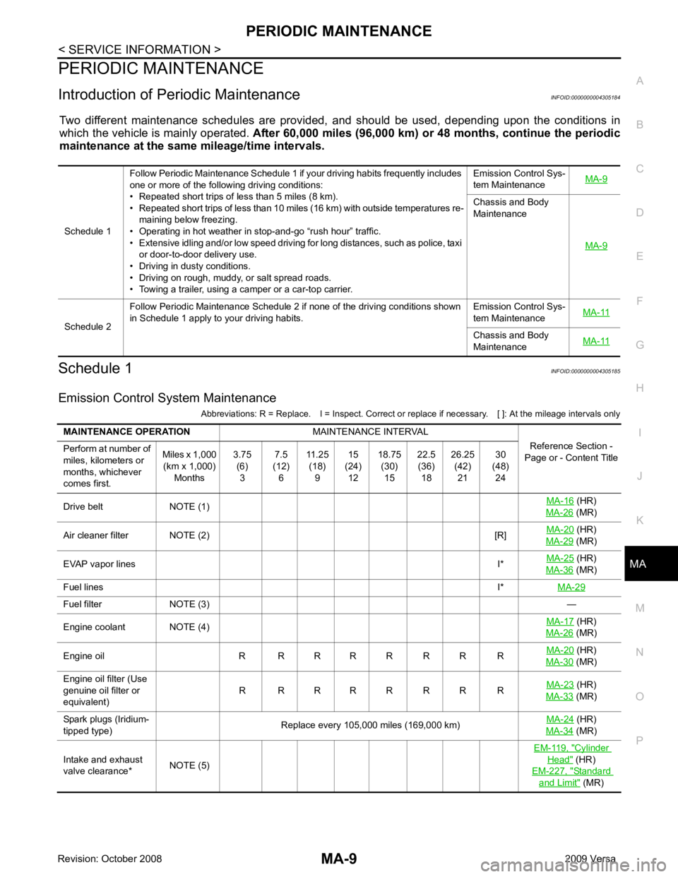
Introduction of Periodic Maintenance INFOID:0000000004305184
Two different maintenance schedules are provi ded, and should be used, depending upon the conditions in
which the vehicle is mainly operated. After 60,000 miles (96,000 km) or 48 months, continue the periodic
maintenance at the same mileage/time intervals.
Schedule 1 INFOID:0000000004305185
Emission Control System Maintenance Abbreviations: R = Replace. I = Inspect. Correct or r eplace if necessary. [ ]: At the mileage intervals only
Schedule 1
Follow Periodic Maintenance Schedule 1 if your driving habits frequently includes
one or more of the following driving conditions:
• Repeated short trips of less than 5 miles (8 km).
• Repeated short trips of less than 10 miles (16 km) with outside temperatures re- maining below freezing.
• Operating in hot weather in stop-and-go “rush hour” traffic.
• Extensive idling and/or low speed driving for long distances, such as police, taxi or door-to-door delivery use.
• Driving in dusty conditions.
• Driving on rough, muddy, or salt spread roads.
• Towing a trailer, using a camper or a car-top carrier. Emission Control Sys-
tem Maintenance MA-9 Chassis and Body
Maintenance
MA-9Schedule 2
Follow Periodic Maintenance Schedule 2 if none of the driving conditions shown
in Schedule 1 apply to your driving habits. Emission Control Sys-
tem Maintenance MA-11 Chassis and Body
Maintenance MA-11 (HR)
MA-26 (MR)
Air cleaner filter NOTE (2) [R]MA-20 (HR)
MA-29 (MR)
EVAP vapor lines I*MA-25 (HR)
MA-36 (MR)
Fuel lines I*MA-29 Fuel filter NOTE (3)
—
Engine coolant NOTE (4) MA-17 (HR)
MA-26 (MR)
Engine oil R R R R R R R R MA-20 (HR)
MA-30 (MR)
Engine oil filter (Use
genuine oil filter or
equivalent) R R R R R R R R
MA-23 (HR)
MA-33 (MR)
Spark plugs (Iridium-
tipped type) Replace every 105,000 miles (169,000 km)
MA-24 (HR)
MA-34 (MR)
Intake and exhaust
valve clearance* NOTE (5) EM-119, " Cylinder
Head " (HR)
EM-227, " Standard
and Limit " (MR)
Page 3754 of 4331
MA
N
O P
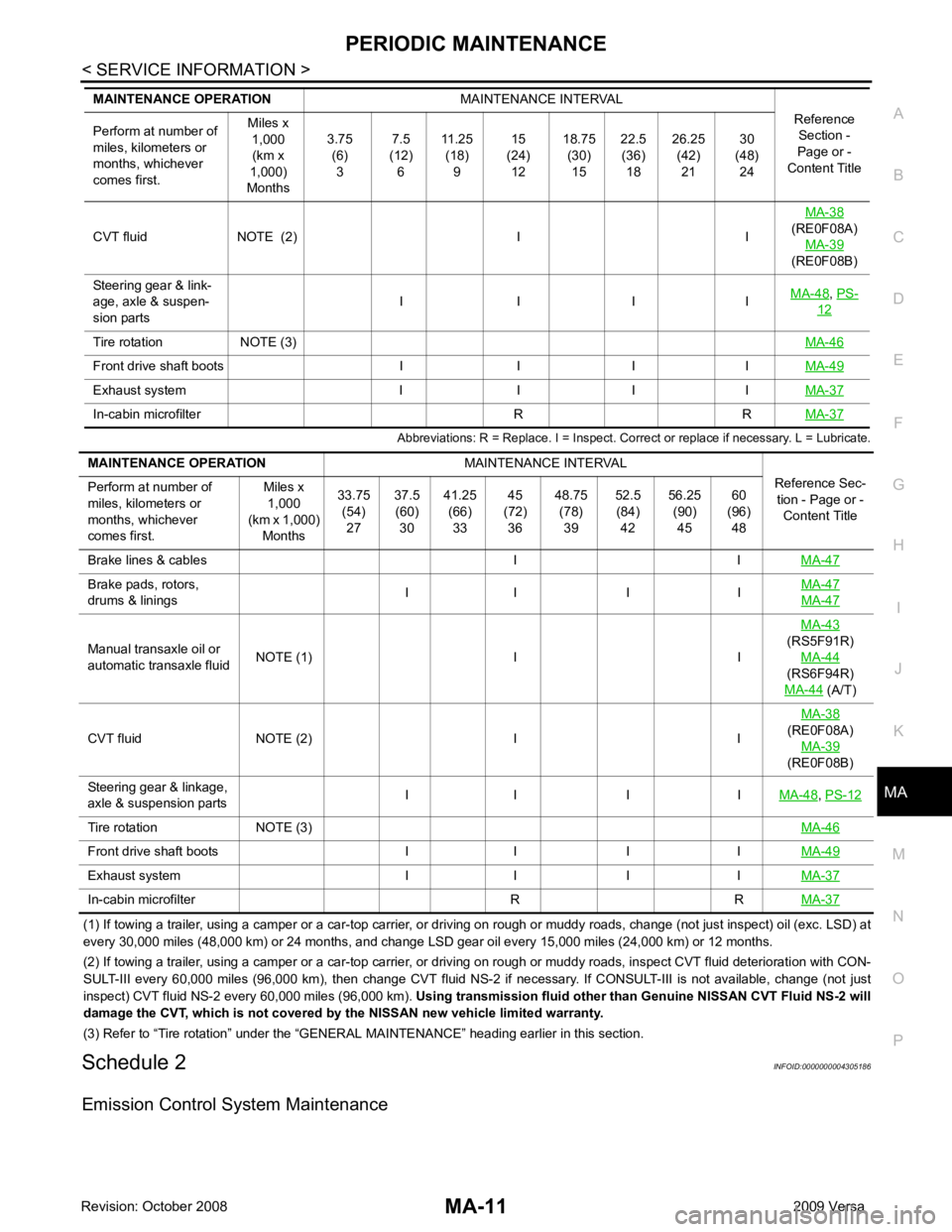
Abbreviations: R = Replace. I = Inspect. Corr
ect or replace if necessary. L = Lubricate.
(1) If towing a trailer, using a camper or a car-top carrier, or driving on rough or muddy roads, change (not just inspect) oil (exc. LSD) at
every 30,000 miles (48,000 km) or 24 months, and change LSD gear oil every 15,000 miles (24,000 km) or 12 months.
(2) If towing a trailer, using a camper or a car-top carrier, or driving on rough or muddy roads, inspect CVT fluid deteriorati on with CON-
SULT-III every 60,000 miles (96,000 km), then change CVT fluid NS-2 if necessary. If CONSULT-III is not available, change (not just
inspect) CVT fluid NS-2 every 60,000 miles (96,000 km). Using transmission fluid other than Genuine NISSAN CVT Fluid NS-2 will
damage the CVT, which is not covered by the NISSAN new vehicle limited warranty.
(3) Refer to “Tire rotation” under the “GENERAL MAINTENANCE” heading earlier in this section.
Schedule 2 INFOID:0000000004305186
Emission Control System Maintenance CVT fluid NOTE (2) I I
MA-38
(RE0F08A) MA-39
(RE0F08B)
Steering gear & link-
age, axle & suspen-
sion parts I I I I
MA-48 ,
PS- 12
Tire rotation NOTE (3)
MA-46Front drive shaft boots I I I I
MA-49Exhaust system I I I I
MA-37In-cabin microfilter R R
MA-37Brake pads, rotors,
drums & linings I I I I MA-47 MA-47
Manual transaxle oil or
automatic transaxle fluid NOTE (1) I I MA-43
(RS5F91R) MA-44
(RS6F94R)
MA-44 (A/T)
CVT fluid NOTE (2) I I MA-38
(RE0F08A)
MA-39
(RE0F08B)
Steering gear & linkage,
axle & suspension parts I I I I
MA-48 ,
PS-12 Tire rotation NOTE (3)
MA-46Front drive shaft boots I I I I
MA-49Exhaust system I I I I
MA-37In-cabin microfilter R R
MA-37
Page 3781 of 4331
MA-38< SERVICE INFORMATION >
CHASSIS AND BODY MAINTENANCE
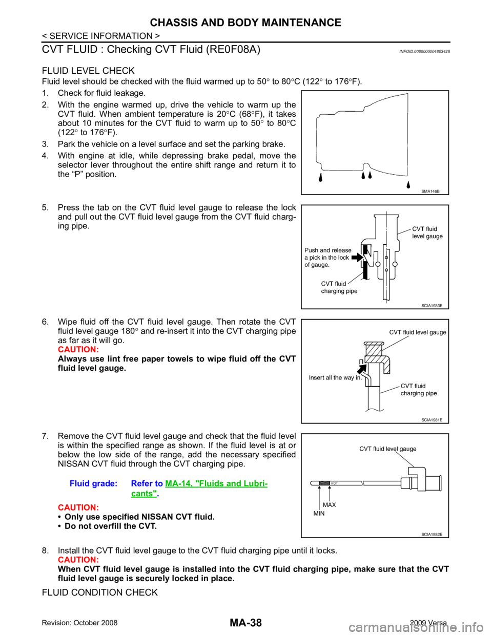
CVT FLUID : Checking CVT Fluid (RE0F08A) INFOID:0000000004803426
FLUID LEVEL CHECK
Fluid level should be checked with the fluid warmed up to 50 ° to 80 °C (122 ° to 176 °F).
1. Check for fluid leakage.
2. With the engine warmed up, drive the vehicle to warm up the CVT fluid. When ambient temperature is 20 °C (68 °F), it takes
about 10 minutes for the CVT fluid to warm up to 50 ° to 80 °C
(122 ° to 176 °F).
3. Park the vehicle on a level surface and set the parking brake.
4. With engine at idle, while depressing brake pedal, move the selector lever throughout the entire shift range and return it to
the “P” position.
5. Press the tab on the CVT fluid level gauge to release the lock and pull out the CVT fluid level gauge from the CVT fluid charg-
ing pipe.
6. Wipe fluid off the CVT fluid level gauge. Then rotate the CVT fluid level gauge 180 ° and re-insert it into the CVT charging pipe
as far as it will go.
CAUTION:
Always use lint free paper towels to wipe fluid off the CVT
fluid level gauge.
7. Remove the CVT fluid level gauge and check that the fluid level is within the specified range as shown. If the fluid level is at or
below the low side of the range, add the necessary specified
NISSAN CVT fluid through the CVT charging pipe.
CAUTION:
• Only use specified NISSAN CVT fluid.
• Do not overfill the CVT.
8. Install the CVT fluid level gauge to the CVT fluid charging pipe until it locks. CAUTION:
When CVT fluid level gauge is in stalled into the CVT fluid charging pipe, make sure that the CVT
fluid level gauge is securely locked in place.
FLUID CONDITION CHECK SMA146B
SCIA1933E
SCIA1931E
Fluid grade: Refer to
MA-14, " Fluids and Lubri-
cants " .
SCIA1932E
Page 3783 of 4331
MA-40< SERVICE INFORMATION >
CHASSIS AND BODY MAINTENANCE
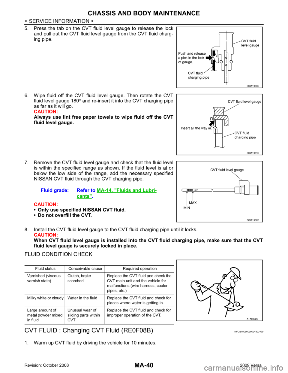
5. Press the tab on the CVT fluid level gauge to release the lock and pull out the CVT fluid level gauge from the CVT fluid charg-
ing pipe.
6. Wipe fluid off the CVT fluid level gauge. Then rotate the CVT fluid level gauge 180 ° and re-insert it into the CVT charging pipe
as far as it will go.
CAUTION:
Always use lint free paper towels to wipe fluid off the CVT
fluid level gauge.
7. Remove the CVT fluid level gauge and check that the fluid level is within the specified range as shown. If the fluid level is at or
below the low side of the range, add the necessary specified
NISSAN CVT fluid through the CVT charging pipe.
CAUTION:
• Only use specified NISSAN CVT fluid.
• Do not overfill the CVT.
8. Install the CVT fluid level gauge to the CVT fluid charging pipe until it locks. CAUTION:
When CVT fluid level gauge is in stalled into the CVT fluid charging pipe, make sure that the CVT
fluid level gauge is securely locked in place.
FLUID CONDITION CHECK
CVT FLUID : Changing CVT Fluid (RE0F08B) INFOID:0000000004803429
1. Warm up CVT fluid by driving the vehicle for 10 minutes. SCIA1933E
SCIA1931E
Fluid grade: Refer to
MA-14, " Fluids and Lubri-
cants " .
SCIA1932E
Fluid status Conceivable cause Required operation
Varnished (viscous
varnish state) Clutch, brake
scorched Replace the CVT fluid and check the
CVT main unit and the vehicle for
malfunctions (wire harness, cooler
pipes, etc.)
Milky white or cloudy Water in the fluid Replace the CVT fluid and check for places where water is getting in.
Large amount of
metal powder mixed
in fluid Unusual wear of
sliding parts within
CVT Replace the CVT fluid and check for
improper operation of the CVT. ATA0022D
Page 3809 of 4331
MT
N
O P
AIR BREATHER HOSE
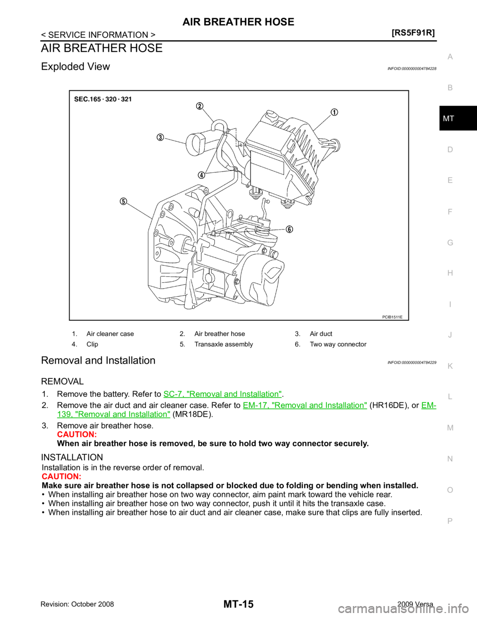
Exploded View INFOID:0000000004784228
Removal and Installation INFOID:0000000004784229
REMOVAL 1. Remove the battery. Refer to SC-7, " Removal and Installation " .
2. Remove the air duct and air cleaner case. Refer to EM-17, " Removal and Installation " (HR16DE), or
EM- 139, " Removal and Installation " (MR18DE).
3. Remove air breather hose. CAUTION:
When air breather hose is removed, be su re to hold two way connector securely.
INSTALLATION Installation is in the reverse order of removal.
CAUTION:
Make sure air breather hose is not collapsed or bl ocked due to folding or bending when installed.
• When installing air breather hose on two way connector, aim paint mark toward the vehicle rear.
• When installing air breather hose on two way connecto r, push it until it hits the transaxle case.
• When installing air breather hose to air duct and air cleaner case, make sure that clips are fully inserted. 1. Air cleaner case 2. Air breather hose 3. Air duct
4. Clip 5. Transaxle assembly 6. Two way connector
Page 3851 of 4331
MT
N
O P
AIR BREATHER HOSE
Removal and Installation INFOID:0000000004305277
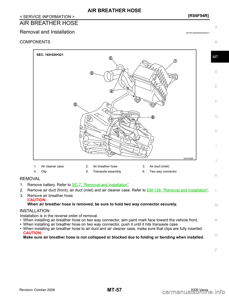
COMPONENTS
REMOVAL 1. Remove battery. Refer to SC-7, " Removal and Installation " .
2. Remove air duct (front), air duct (inlet) and air cleaner case. Refer to EM-139, " Removal and Installation " .
3. Remove air breather hose. CAUTION:
When air breather hose is removed, be su re to hold two way connector securely.
INSTALLATION Installation is in the reverse order of removal.
• When installing air breather hose on two way connector, aim paint mark face toward the vehicle front.
• When installing air breather hose on two way connec tor, push it until it hits transaxle case.
• When installing air breather hose to air duct and air cleaner case, make sure that clips are fully inserted. CAUTION:
Make sure air breather hose is not collapsed or bl ocked due to folding or bending when installed.
1. Air cleaner case 2. Air breather hose 3. Air duct (inlet)
4. Clip 5. Transaxle assembly 6. Two way connector