2009 NISSAN LATIO air condition
[x] Cancel search: air conditionPage 3156 of 4331

EM
NP
O
How to Select Piston and Bearing
INFOID:0000000004307160
DESCRIPTION
• The identification grade stamped on each part is the grade for the dimension measured in new condition.
This grade cannot apply to reused parts.
• For reused or repaired parts, measure the dimens ion accurately. Determine the grade by comparing the
measurement with the values of each selection table.
• For details of the measurement method of each part , the reuse standards and the selection method of the
selective fitting parts, follow the applicable procedures.
HOW TO SELECT PISTON
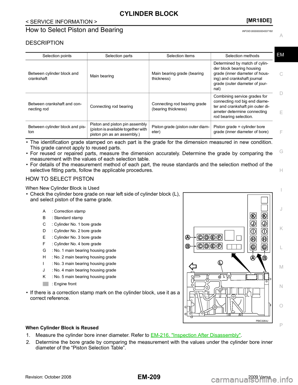
When New Cylinder Block is Used • Check the cylinder bore grade on rear left side of cylinder block (L), and select piston of the same grade.
• If there is a correction stamp mark on the cylinder block, use it as a correct reference.
When Cylinder Block is Reused 1. Measure the cylinder bore inner diameter. Refer to EM-216, " Inspection After Disassembly " .
2. Determine the bore grade by comparing the measur ement with the values under the cylinder bore inner
diameter of the “Piston Selection Table”. Selection points Selection parts Selection items Selection methods
Between cylinder block and
crankshaft Main bearing
Main bearing grade (bearing
thickness) Determined by match of cylin-
der block bearing housing
grade (inner diameter of hous-
ing) and crankshaft journal
grade (outer diameter of jour-
nal)
Between crankshaft and con-
necting rod Connecting rod bearing
Connecting rod bearing grade
(bearing thickness) Combining service grades for
connecting rod big end diame-
ter and crankshaft pin outer di-
ameter determine connecting
rod bearing selection.
Between cylinder block and pis-
ton Piston and piston pin assembly
(piston is available together with
piston pin as an assembly.) Piston grade (piston outer diam-
eter) Piston grade = cylinder bore
grade (inner diameter of bore) A : Correction stamp
B : Standard stamp
C : Cylinder No. 1 bore grade
D : Cylinder No. 2 bore grade
E : Cylinder No. 3 bore grade
F : Cylinder No. 4 bore grade
G : No. 1 main bearing housing grade
H : No. 2 main bearing housing grade
I : No. 3 main bearing housing grade
J : No. 4 main bearing housing grade
K : No. 5 main bearing housing grade
: Engine front
Page 3187 of 4331
![NISSAN LATIO 2009 Service Repair Manual PREPARATION
EX-3
< PREPARATION >
[HR16DE] C
D E
F
G H
I
J
K L
M A EX
NP
O
PREPARATION
PREPARATION
Special Service Tool INFOID:0000000004784375
Commercial Service Tool INFOID:0000000004784394
Tool numb NISSAN LATIO 2009 Service Repair Manual PREPARATION
EX-3
< PREPARATION >
[HR16DE] C
D E
F
G H
I
J
K L
M A EX
NP
O
PREPARATION
PREPARATION
Special Service Tool INFOID:0000000004784375
Commercial Service Tool INFOID:0000000004784394
Tool numb](/manual-img/5/57359/w960_57359-3186.png)
PREPARATION
EX-3
< PREPARATION >
[HR16DE] C
D E
F
G H
I
J
K L
M A EX
NP
O
PREPARATION
PREPARATION
Special Service Tool INFOID:0000000004784375
Commercial Service Tool INFOID:0000000004784394
Tool number
Tool name Description
KV10114400
(J-38365)
Heated oxygen sensor wrench Loosening or tightening heated oxygen sen-
sor
a: 22 mm (0.87 in) NT636
(Kent-Moore No.)
Tool name Description
(J-43897-18)
(J-43897-12)
Heated oxygen sensor thread cleaner Reconditioning the exhaust system threads
before installing new heated oxygen and Air
fuel ratio sensors (Use with anti-seize lubri-
cant shown below.)
a: 18 mm (0.71 in) dia. for zirconia heated
oxygen sensor
b: 12 mm (0.47 in) dia. for titania heated ox-
ygen sensor
Anti-seize lubricant (Permatex 133AR
or equivalent meeting MIL specifica-
tion MIL-A-907) Lubricating heated oxygen sensor thread
cleaner when reconditioning exhaust system
threads
Power tool Loosening bolts and nuts AEM488
AEM489
PBIC0190E
Page 3192 of 4331
![NISSAN LATIO 2009 Service Repair Manual EX-8< SERVICE INFORMATION >
[MR18DE]
PREPARATION
PREPARATION
Special Service Tool INFOID:0000000004306676
Commercial Service Tool INFOID:0000000004675326
Tool number
Tool name Description
KV10114400
( NISSAN LATIO 2009 Service Repair Manual EX-8< SERVICE INFORMATION >
[MR18DE]
PREPARATION
PREPARATION
Special Service Tool INFOID:0000000004306676
Commercial Service Tool INFOID:0000000004675326
Tool number
Tool name Description
KV10114400
(](/manual-img/5/57359/w960_57359-3191.png)
EX-8< SERVICE INFORMATION >
[MR18DE]
PREPARATION
PREPARATION
Special Service Tool INFOID:0000000004306676
Commercial Service Tool INFOID:0000000004675326
Tool number
Tool name Description
KV10114400
(J-38365)
Heated oxygen sensor wrench Loosening or tightening heated oxygen sen-
sor
a: 22 mm (0.87 in) NT636
(Kent-Moore No.)
Tool name Description
(J-43897-18)
(J-43897-12)
Heated oxygen sensor thread cleaner Reconditioning the exhaust system threads
before installing new heated oxygen and Air
fuel ratio sensors (Use with anti-seize lubri-
cant shown below.)
a: 18 mm (0.71 in) dia. for zirconia heated
oxygen sensor
b: 12 mm (0.47 in) dia. for titania heated ox-
ygen sensor
Anti-seize lubricant (Permatex 133AR
or equivalent meeting MIL specifica-
tion MIL-A-907) Lubricating heated oxygen sensor thread
cleaner when reconditioning exhaust system
threads
Power tool Loosening bolts and nuts AEM488
AEM489
PBIC0190E
Page 3237 of 4331

PRECAUTIONS
FSU-3
< SERVICE INFORMATION >
C
D
F
G H
I
J
K L
M A
B FSU
N
O P
5. When the repair work is completed, return the ignition switch to the
″LOCK ″ position before connecting
the battery cables. (At this time, the steering lock mechanism will engage.)
6. Perform a self-diagnosis check of al l control units using CONSULT-III.
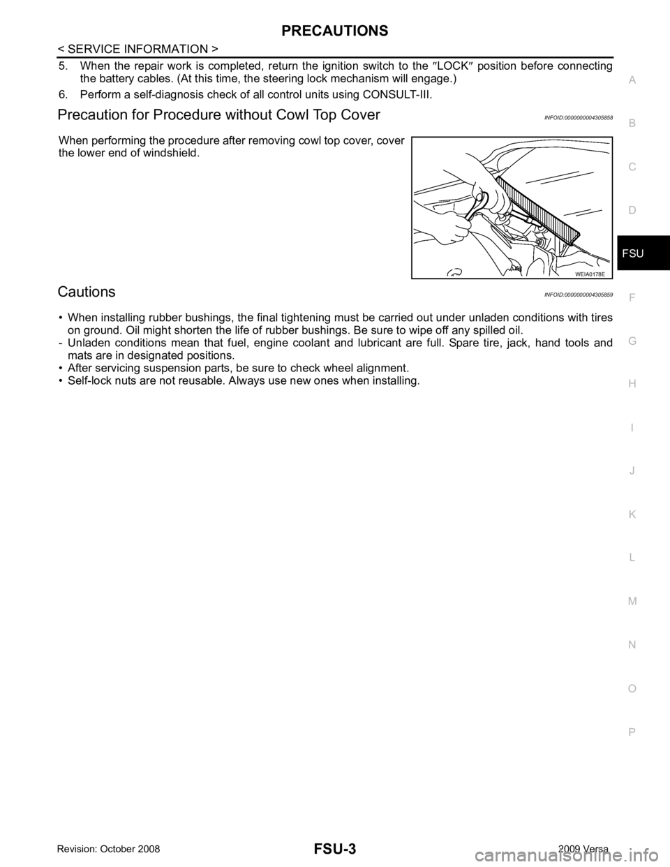
Precaution for Procedur e without Cowl Top Cover INFOID:0000000004305858
When performing the procedure after removing cowl top cover, cover
the lower end of windshield.
Cautions INFOID:0000000004305859
• When installing rubber bushings, the final tightening mu st be carried out under unladen conditions with tires
on ground. Oil might shorten the life of rubber bushings. Be sure to wipe off any spilled oil.
- Unladen conditions mean that fuel, engine coolant and l ubricant are full. Spare tire, jack, hand tools and
mats are in designated positions.
• After servicing suspension parts, be sure to check wheel alignment.
• Self-lock nuts are not reusable. A lways use new ones when installing. WEIA0178E
Page 3241 of 4331

FSU
N
O P
FRONT SUSPENSION ASSEMBLY
On-Vehicle Inspection and Service INFOID:0000000004305863
Make sure the mounting conditions (looseness, back lash) of each component and component conditions
(wear, damage) are normal.
INSPECTION OF LOWER BALL JOINT END PLAY 1. Set front wheels in a straight-ahead position. Do not depress brake pedal.
2. Place an iron bar or similar tool bet ween transverse link and steering knuckle.
3. Measure axial end play by prying it up and down.
CAUTION:
Be careful not to damage ball joint boot. Do not damage the installation position by applying
excessive force.
STRUT INSPECTION Check for oil leakage, damage and replace as necessary.
Wheel Alignment Inspection INFOID:0000000004305864
PRELIMINARY INSPECTION WARNING:
Always adjust the alignment with the vehicle on a flat surface.
NOTE:
If alignment is out of specification, inspect and r eplace any damaged or worn rear suspension parts before
making any adjustments.
1. Check and adjust the wheel alignment with the vehicle under unladen conditions. “Unladen conditions”
means that the fuel, coolant, and lubricant are full; and that the spare tire, jack, hand tools and mats are in
their designated positions.
2. Check the tires for incorrect air pressure and excessive wear.
3. Check the wheels for run out and damage. Refer to WT-6, " Inspection " .
4. Check the wheel bearing axial end play. Refer to FAX-6, " On-Vehicle Inspection and Service " .
5. Check the shock absorbers for leaks or damage.
6. Check each mounting point of the suspension components for any excessive looseness or damage.
7. Check each link, arm, and the suspension member for any damage.
8. Check the vehicle height. Refer to FSU-19, " Wheelarch Height (Unladen*) " .
GENERAL INFORMATION AND RECOMMENDATIONS 1. A Four-Wheel Thrust Alignment should be performed. • This type of alignment is re commended for any NISSAN vehicle.
• The four-wheel “thrust” process helps ensure that the vehicle is properly aligned and the steering wheel
is centered.
• The alignment machine itself should be ca pable of accepting any NISSAN vehicle.
• The alignment machine should be checked to ensure that it is level.
2. Make sure the alignment machine is properly calibrated. • Your alignment machine should be regularly calib rated in order to give correct information.
• Check with the manufacturer of your specific a lignment machine for their recommended Service/Cali-
bration Schedule.
THE ALIGNMENT PROCESS IMPORTANT: Use only the alignment specifications listed in this Service Manual. Refer to FSU-17, " Wheel
Alignment (Unladen*) " .
1. When displaying the alignment settings, many alignm ent machines use “indicators”: (Green/red, plus or
minus, Go/No Go). Do NOT use these indicators.
• The alignment specifications programmed into your alignment machine that operate these indicators
may not be correct. Axial end play : 0 mm (0 in)
Page 3254 of 4331

GI
SECTION GI
N
O P
CONTENTS
GENERAL INFORMATION
SERVICE INFORMATION .. ..........................2
PRECAUTIONS .............................................. .....2
Description .......................................................... ......2
Precaution for Supplemental Restraint System
(SRS) "AIR BAG" and "SEAT BELT PRE-TEN-
SIONER" ............................................................. ......
2
Precaution Necessary fo r Steering Wheel Rota-
tion After Battery Disconnect ............................... ......
2
General Precaution ............................................. ......3
Precaution for Three Way Catalyst ..................... ......4
Precaution for Fuel (Unleaded Regular Gasoline
Recommended) ................................................... ......
4
Precaution for Multiport Fuel Injection System or
Engine Control System ....................................... ......
5
Precaution for Hoses ........................................... ......5
Precaution for Engine Oils .................................. ......6
Precaution for Air Conditioning ........................... ......6
HOW TO USE THIS MANUAL ....................... .....7
Description .......................................................... ......7
Terms .................................................................. ......7
Units .................................................................... ......7
Contents .............................................................. ......7
Relation between Illustrations and Descriptions . ......8
Component .......................................................... ......8
How to Follow Trouble Diagnosis ........................ ......9
How to Read Wiring Diagr am ..................................13
Abbreviations ...................................................... ....20
SERVICE INFORMATION FOR ELECTRICAL
INCIDENT ....................................................... ....
22
How to Check Terminal ...........................................22 How to Perform Efficient Diagnosis for an Electri-
cal Incident .......................................................... ....
25
Control Units and Electrical Parts ........................ ....32
CONSULT-III CHECKING SYSTEM ................. 35
Description ........................................................... ....35
Function and System Application ........................ ....35
CONSULT-III Data Link Connector (DLC) Circuit ....36
LIFTING POINT ................................................. 38
Special Service Tool ............................................ ....38
Garage Jack and Safety Stand and 2-Pole Lift ... ....38
Board-On Lift ....................................................... ....39
TOW TRUCK TOWING ..................................... 40
Tow Truck Towing ............................................... ....40
Vehicle Recovery (Freeing a Stuck Vehicle) ....... ....40
TIGHTENING TORQUE OF STANDARD
BOLTS ............................................................... 41
Tightening Torque Table ..................................... ....41
RECOMMENDED CHEMICAL PRODUCTS
AND SEALANTS ............................................... 42
Recommended Chemical Product and Sealant ... ....42
IDENTIFICATION INFORMATION .................... 43
Model Variation .................................................... ....43
Dimensions .......................................................... ....46
Wheels & Tires .................................................... ....46
TERMINOLOGY ................................................ 47
SAE J1930 Terminology List ............................... ....47
Page 3280 of 4331

GI
N
O P
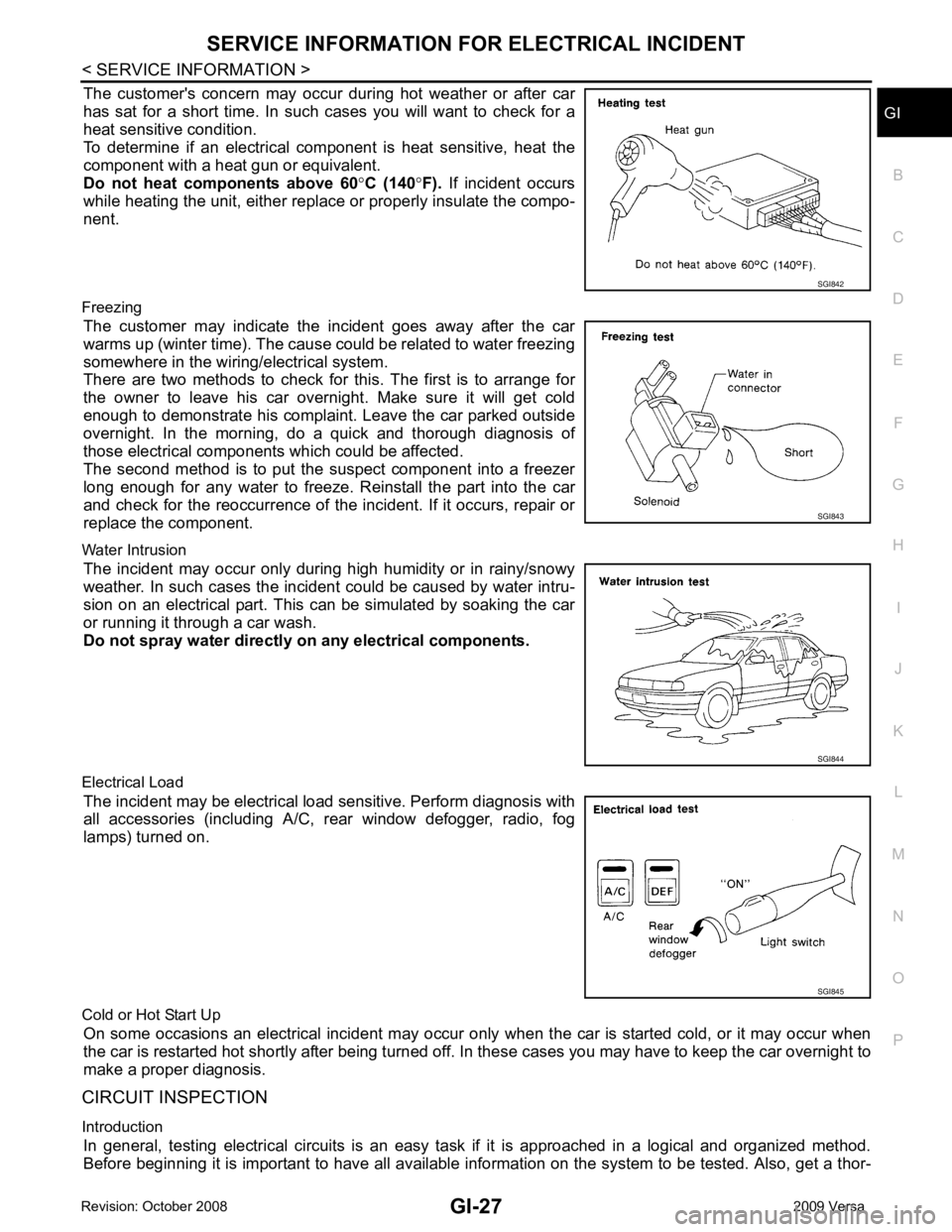
The customer's concern may occur during hot weather or after car
has sat for a short time. In such cases you will want to check for a
heat sensitive condition.
To determine if an electrical com ponent is heat sensitive, heat the
component with a heat gun or equivalent.
Do not heat components above 60 °C (140 °F). If incident occurs
while heating the unit, either replace or properly insulate the compo-
nent.
Freezing The customer may indicate the incident goes away after the car
warms up (winter time). The cause could be related to water freezing
somewhere in the wiring/electrical system.
There are two methods to check for this. The first is to arrange for
the owner to leave his car overnight. Make sure it will get cold
enough to demonstrate his complaint. Leave the car parked outside
overnight. In the morning, do a quick and thorough diagnosis of
those electrical components which could be affected.
The second method is to put the suspect component into a freezer
long enough for any water to freeze. Reinstall the part into the car
and check for the reoccurrence of the incident. If it occurs, repair or
replace the component.
Water Intrusion The incident may occur only during high humidity or in rainy/snowy
weather. In such cases the incident could be caused by water intru-
sion on an electrical part. This c an be simulated by soaking the car
or running it through a car wash.
Do not spray water directly on any electrical components.
Electrical Load The incident may be electrical load sensitive. Perform diagnosis with
all accessories (including A/C, rear window defogger, radio, fog
lamps) turned on.
Cold or Hot Start Up On some occasions an electrical incident may occur only when the car is started cold, or it may occur when
the car is restarted hot shortly after being turned off. In these cases you may have to keep the car overnight to
make a proper diagnosis.
CIRCUIT INSPECTION
Introduction In general, testing electrical circuits is an easy ta sk if it is approached in a logical and organized method.
Before beginning it is important to have all available in formation on the system to be tested. Also, get a thor- SGI843
SGI845
Page 3288 of 4331

GI
N
O P
CONSULT-III CHECKING SYSTEM
Description INFOID:0000000004307366
• CONSULT-III is a hand-held type tester. When it is connected with a diagnostic connector equipped on the vehicle side, it will communicate with the contro l unit equipped in the vehicle and then enable various kinds
of diagnostic tests.
• Refer to CONSULT-III Operator's Manual for more information.
Function and System Application INFOID:0000000004307367
x: Applicable.
*1: If equipped.
*2: With automatic transmission (A/T).
*3: With continuously variable transmission (CVT).
*4: With security card installed. Diagnostic test mode FunctionENGINE
ABS* 1
AIR BAG EPS
IPDM E/R BCM
METER/M&A
INTELLIGENT KEY* 1
TRANSMISSION* 2
TRANSMISSION* 3
Work support This mode enables a technician to adjust some devices faster and
more accurately by following indications on CONSULT-III. x - - - - x - x x x
Self-diagnostic results Self-diagnostic results can be read and erased quickly. x x x x x x x x x x
Trouble diagnostic record Current self-diagnostic results and all trouble diagnostic records
previously stored can be read. - - x - - - - - - -
Data monitor Input/Output data in the ECU can be read. x x x x x x x x x x
CAN diagnostic support
monitor The communication condition of CAN communication line can be
read. x x - x x x x x x x
Calibration data* 2
Shows unit calibration IDs, offsets and gains. This data is stored in
the ECU memory. - - - - - - - - - x
Active test Diagnostic Test Mode in which CONSULT-III drives actuators apart
from ECU shifting some parameters in a specified range. x x - - x x - x - -
Function test This mode can show results of self-diagnosis of ECU with either
"OK" or "NG". For engines, more practical tests regarding sensors/
switches and/or actuators are available. x x x - - - - - x x
DTC & SRT confirmation The results of SRT (System Readiness Test) and the self-diagno-
sis status/result can be confirmed. x - - - - - - - x -
DTC work support The operating condition to confirm Diagnosis Trouble Codes can
be selected. x - - - - - - - x -
ECM/ECU part number ECM/ECU part number can be read. x x - x - x - x x x
ECU discriminated No. Classification number of a replacement ECU can be read to pre-
vent an incorrect ECU from being installed. - - x - - - - - - -
Passenger airbag Displays the STATUS (readiness) of front passenger air bag. - - x - - - - - - -
Configuration Sets control module parameters to match vehicle options. - - - - - x - - - -
Control unit initialization *4
All registered ignition key IDs in NATS components can be initial-
ized and new IDs can be registered. - - - - - x - - - -
PIN Read *4
This mode enables technician to get BCM-specific 5-digit code. - - - - - x - - - -