2009 NISSAN LATIO heating
[x] Cancel search: heatingPage 2777 of 4331

EC
NP
O
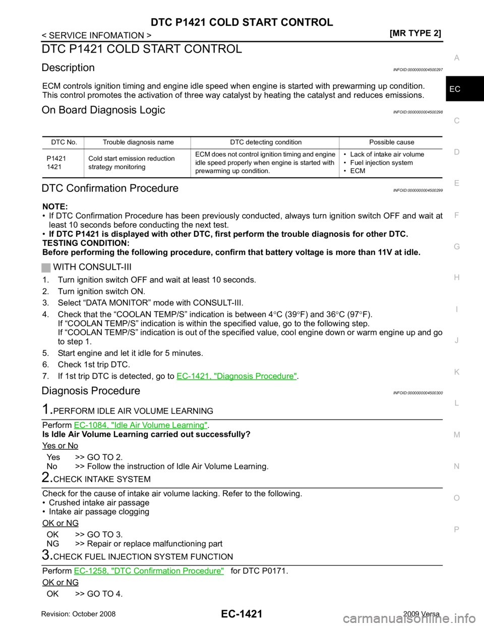
DTC P1421 COLD START CONTROL
Description INFOID:0000000004500297
ECM controls ignition timing and engine idle speed when engine is started with prewarming up condition.
This control promotes the activation of three way ca talyst by heating the catalyst and reduces emissions.
On Board Diagnosis Logic INFOID:0000000004500298
DTC Confirmation Procedure INFOID:0000000004500299
NOTE:
• If DTC Confirmation Procedure has been previously conduc ted, always turn ignition switch OFF and wait at
least 10 seconds before conducting the next test.
• If DTC P1421 is displayed with other DTC, firs t perform the trouble diagnosis for other DTC.
TESTING CONDITION:
Before performing the following procedure, confirm that battery voltage is more than 11V at idle.
WITH CONSULT-III
1. Turn ignition switch OFF and wait at least 10 seconds.
2. Turn ignition switch ON.
3. Select “DATA MONITOR” mode with CONSULT-III.
4. Check that the “COOLAN TE MP/S” indication is between 4°C (39 °F) and 36 °C (97 °F).
If “COOLAN TEMP/S” indication is within the specified value, go to the following step.
If “COOLAN TEMP/S” indication is out of the s pecified value, cool engine down or warm engine up and go
to step 1.
5. Start engine and let it idle for 5 minutes.
6. Check 1st trip DTC.
7. If 1st trip DTC is detected, go to EC-1421, " Diagnosis Procedure " .
Diagnosis Procedure INFOID:0000000004500300Idle Air Volume Learning " .
Is Idle Air Volume Learning carried out successfully?
Yes or No Yes >> GO TO 2.
No >> Follow the instruction of Idle Air Volume Learning. OK >> GO TO 3.
NG >> Repair or replace malfunctioning part DTC Confirmation Procedure " for DTC P0171.
OK or NG OK >> GO TO 4.DTC No. Trouble diagnosis name DTC detecting condition Possible cause
P1421
1421 Cold start emission reduction
strategy monitoring ECM does not control ignition timing and engine
idle speed properly when engine is started with
prewarming up condition. • Lack of intake air volume
• Fuel injection system
• ECM
Page 3280 of 4331

GI
N
O P
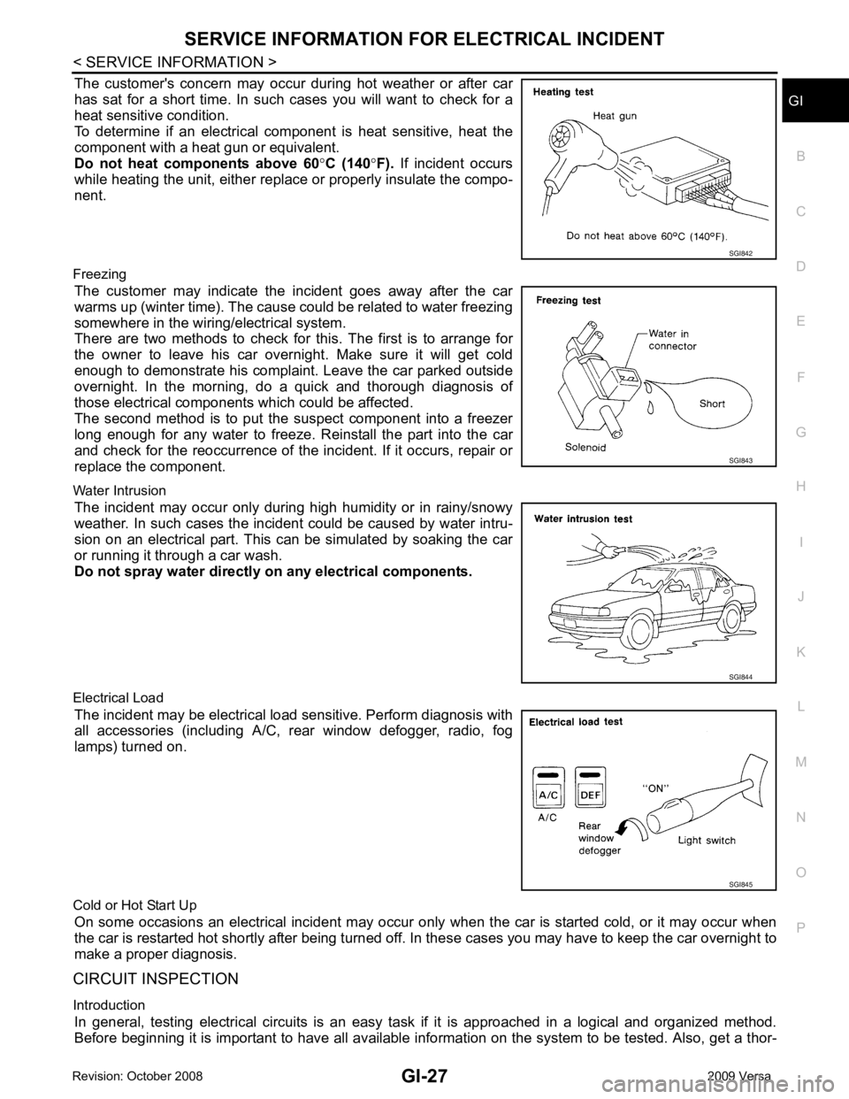
The customer's concern may occur during hot weather or after car
has sat for a short time. In such cases you will want to check for a
heat sensitive condition.
To determine if an electrical com ponent is heat sensitive, heat the
component with a heat gun or equivalent.
Do not heat components above 60 °C (140 °F). If incident occurs
while heating the unit, either replace or properly insulate the compo-
nent.
Freezing The customer may indicate the incident goes away after the car
warms up (winter time). The cause could be related to water freezing
somewhere in the wiring/electrical system.
There are two methods to check for this. The first is to arrange for
the owner to leave his car overnight. Make sure it will get cold
enough to demonstrate his complaint. Leave the car parked outside
overnight. In the morning, do a quick and thorough diagnosis of
those electrical components which could be affected.
The second method is to put the suspect component into a freezer
long enough for any water to freeze. Reinstall the part into the car
and check for the reoccurrence of the incident. If it occurs, repair or
replace the component.
Water Intrusion The incident may occur only during high humidity or in rainy/snowy
weather. In such cases the incident could be caused by water intru-
sion on an electrical part. This c an be simulated by soaking the car
or running it through a car wash.
Do not spray water directly on any electrical components.
Electrical Load The incident may be electrical load sensitive. Perform diagnosis with
all accessories (including A/C, rear window defogger, radio, fog
lamps) turned on.
Cold or Hot Start Up On some occasions an electrical incident may occur only when the car is started cold, or it may occur when
the car is restarted hot shortly after being turned off. In these cases you may have to keep the car overnight to
make a proper diagnosis.
CIRCUIT INSPECTION
Introduction In general, testing electrical circuits is an easy ta sk if it is approached in a logical and organized method.
Before beginning it is important to have all available in formation on the system to be tested. Also, get a thor- SGI843
SGI845
Page 3886 of 4331

MTC
N
O P
CONTENTS
MANUAL AIR CONDITIONER
SERVICE INFORMATION .. ..........................3
PRECAUTIONS .............................................. .....3
Precaution for Supplemental Restraint System
(SRS) "AIR BAG" and "SEAT BELT PRE-TEN-
SIONER" ............................................................. ......
3
Precaution Necessary fo r Steering Wheel Rota-
tion After Battery Disconnect ............................... ......
3
Precaution for Procedure without Cowl Top Cover ......4
Precaution for Working with HFC-134a (R-134a) ......4
General Refrigerant Precaution .......................... ......4
Oil Precaution ...................................................... ......5
Precaution for Refrigeran t Connection ......................5
Precaution for Service of Compressor ................ ......7
Precaution for Service Equipment ....................... ......8
Precaution for Leak Detection Dye ..................... ......9
PREPARATION .............................................. ....11
HFC-134a (R-134a) Service Tool and Equipment ....11
Commercial Service Tool .................................... ....13
REFRIGERATION SYSTEM .......................... ....15
Refrigerant Cycle ................................................ ....15
Refrigerant System Protec tion ................................15
Component Part Location ................................... ....16
OIL .................................................................. ....17
Maintenance of Oil Quantity in Compressor ....... ....17
AIR CONDITIONER CONTROL ..................... ....19
Control Operation ................................................ ....19
Discharge Air Flow .............................................. ....20
System Description ............................................. ....20
TROUBLE DIAGNOSIS ................................. ....22
CONSULT-II Function (BCM) .............................. ....22
How to Perform Trouble Diagnosis for Quick and
Accurate Repair ........... ...........................................
22
Component Parts and Harness Connector Loca-
tion ...................................................................... ....
23
Schematic ........................................................... ....25
Wiring Diagram - Heater - ................................... ....26 Wiring Diagram - A/C,M - ....................................
....27
Operational Check ............................................... ....30
Mode Door ........................................................... ....31
Air Mix Door ......................................................... ....32
Intake Door .......................................................... ....33
Front Blower Motor Circuit .......................................33
Magnet Clutch Circuit (If Equipped) ..................... ....37
Insufficient Cooling .............................................. ....45
Insufficient Heating .............................................. ....52
Noise ................................................................... ....53
CONTROLLER .................................................. 55
Removal and Installation ..................................... ....55
Disassembly and Assembly ................................. ....56
THERMO CONTROL AMPLIFIER .................... 57
Removal and Installation ..................................... ....57
A/C UNIT ASSEMBLY ...................................... 58
Removal and Installation ..................................... ....58
Disassembly and Assembly ................................. ....60
BLOWER MOTOR ............................................ 62
Removal and Installation ..................................... ....62
INTAKE DOOR .................................................. 63
Intake Door Cable Adjustment ............................. ....63
AIR MIX DOOR ................................................. 64
Air Mix Door Cable Adjustment ........................... ....64
MODE DOOR .................................................... 65
Mode Door Cable Adjustment ............................. ....65
BLOWER FAN RESISTOR ............................... 66
Removal and Installation ..................................... ....66
HEATER CORE ................................................. 67
Removal and Installation ..................................... ....67
AIR CONDITIONER FILTER ............................. 68
Removal and Installation ..................................... ....68
Page 3908 of 4331

MTC
N
O P
Component Parts and Har
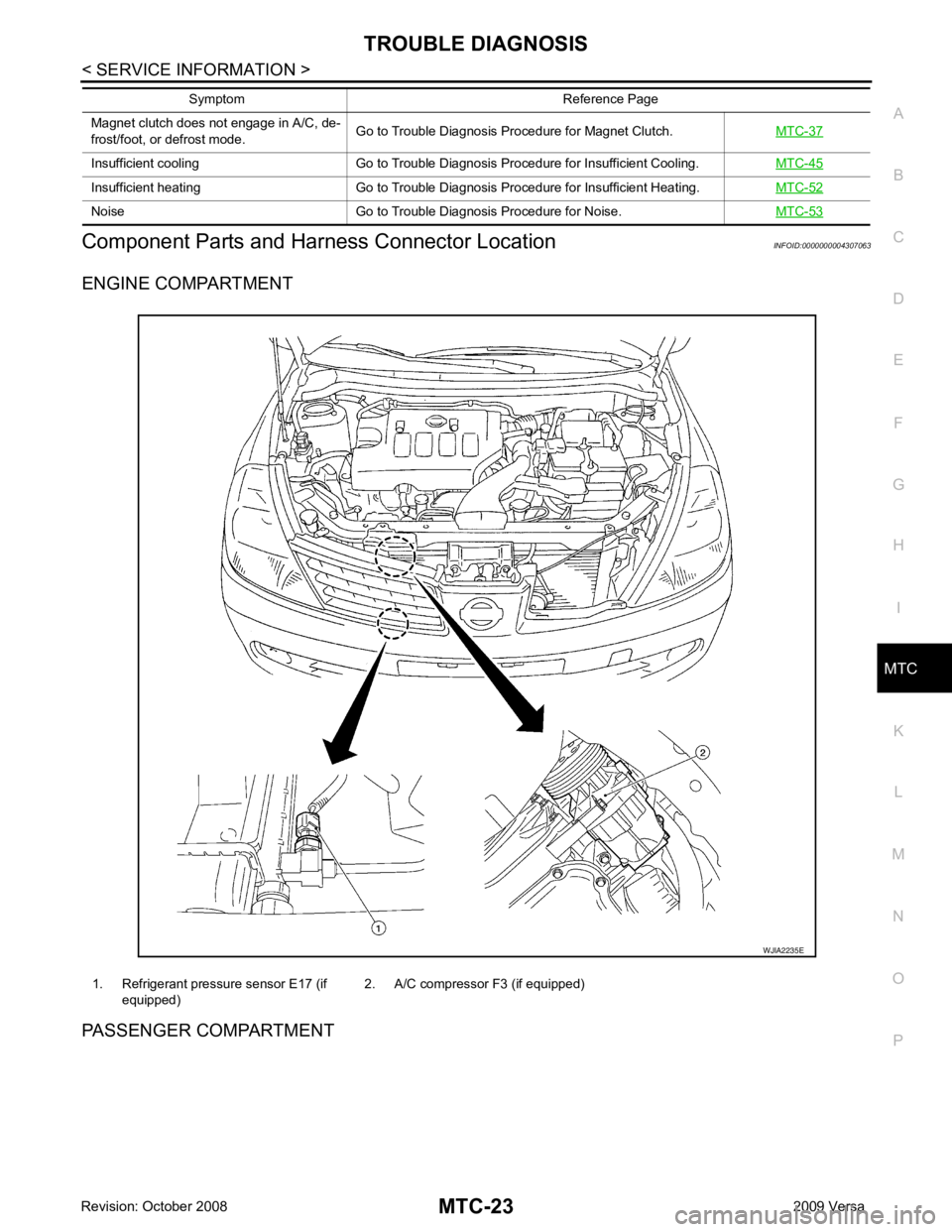
ness Connector Location INFOID:0000000004307063
ENGINE COMPARTMENT
PASSENGER COMPARTMENT Magnet clutch does not engage in A/C, de-
frost/foot, or defrost mode. Go to Trouble Diagnosis Procedure for Magnet Clutch.
MTC-37Insufficient cooling Go to Trouble Diagnosis Procedure for Insufficient Cooling.
MTC-45Insufficient heating Go to Trouble Diagnosis Procedure for Insufficient Heating.
MTC-52Noise Go to Trouble Diagnosis Procedure for Noise.
MTC-53Symptom Reference Page
1. Refrigerant pressure sensor E17 (if
equipped) 2. A/C compressor F3 (if equipped)
Page 3916 of 4331

MTC
N
O P
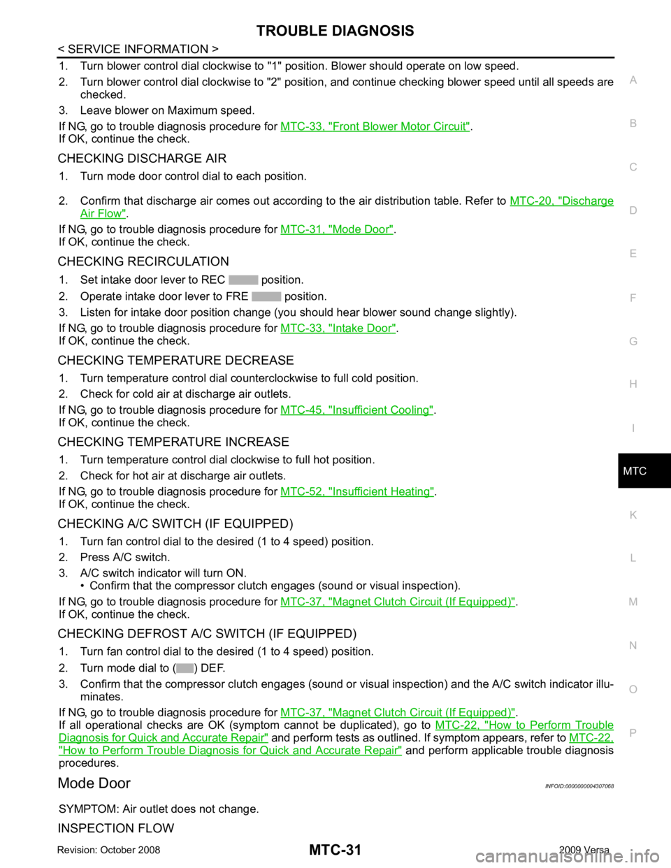
1. Turn blower control dial clockwise to "1" position. Blower should operate on low speed.
2. Turn blower control dial clockwise to "2" position, and continue checking blower speed until all speeds are
checked.
3. Leave blower on Maximum speed.
If NG, go to trouble diagnosis procedure for MTC-33, " Front Blower Motor Circuit " .
If OK, continue the check.
CHECKING DISCHARGE AIR 1. Turn mode door control dial to each position.
2. Confirm that discharge air comes out accord ing to the air distribution table. Refer to MTC-20, " Discharge
Air Flow " .
If NG, go to trouble diagnosis procedure for MTC-31, " Mode Door " .
If OK, continue the check.
CHECKING RECIRCULATION 1. Set intake door lever to REC position.
2. Operate intake door lever to FRE position.
3. Listen for intake door position change (you should hear blower sound change slightly).
If NG, go to trouble diagnosis procedure for MTC-33, " Intake Door " .
If OK, continue the check.
CHECKING TEMPERATURE DECREASE 1. Turn temperature control dial counterclockwise to full cold position.
2. Check for cold air at discharge air outlets.
If NG, go to trouble diagnosis procedure for MTC-45, " Insufficient Cooling " .
If OK, continue the check.
CHECKING TEMPERATURE INCREASE 1. Turn temperature control dial clockwise to full hot position.
2. Check for hot air at discharge air outlets.
If NG, go to trouble diagnosis procedure for MTC-52, " Insufficient Heating " .
If OK, continue the check.
CHECKING A/C SWITCH (IF EQUIPPED) 1. Turn fan control dial to the desired (1 to 4 speed) position.
2. Press A/C switch.
3. A/C switch indicator will turn ON. • Confirm that the compressor clutch engages (sound or visual inspection).
If NG, go to trouble diagnosis procedure for MTC-37, " Magnet Clutch Circuit (If Equipped) " .
If OK, continue the check.
CHECKING DEFROST A/C SWITCH (IF EQUIPPED) 1. Turn fan control dial to the desired (1 to 4 speed) position.
2. Turn mode dial to ( ) DEF.
3. Confirm that the compressor clutch engages (sound or vi sual inspection) and the A/C switch indicator illu-
minates.
If NG, go to trouble diagnosis procedure for MTC-37, " Magnet Clutch Circuit (If Equipped) " .
If all operational checks are OK (symptom cannot be duplicated), go to MTC-22, " How to Perform Trouble
Diagnosis for Quick and Accurate Repair " and perform tests as outlined. If symptom appears, refer to
MTC-22," How to Perform Trouble Diagnosis for Quick and Accurate Repair " and perform applicable trouble diagnosis
procedures.
Mode Door INFOID:0000000004307068
SYMPTOM: Air outlet does not change.
INSPECTION FLOW