Page 936 of 4331

Changing Engine Coolant " .
CAUTION:
• Perform this step when engine is cold.
• Do not spill engine coolant on drive belt.
2. Remove air duct (inlet). Refer to EM-139, " Component " .
3. Remove reservoir tank. Refer to CO-38, " Component " .
4. Disconnect radiator hose (upper) at radiator side. Refer to CO-38, " Component " .
5. Disconnect harness connectors from fan motor, and move harness aside.
6. Remove cooling fan assembly. CAUTION:
Be careful not to damage or scratch the radiator core.
INSTALLATION
Installation is in the reverse order of removal.
• Cooling fans are controlled by ECM. For details, refer to EC-886, " System Description " .
CAUTION:
Be careful not to damage or scratch the radiator core.
Disassembly and Assembly INFOID:0000000004305243
DISASSEMBLY
1. Remove cooling fan from fan motor.
2. Remove fan motor from fan shroud.
INSPECTION AFTER DISASSEMBLY
Inspect cooling fan for crack or unusual bend.
• If anything is found, replace cooling fan.
ASSEMBLY
Assembly is in the reverse order of disassembly.
Page 937 of 4331

CO
NP
O
WATER PUMP
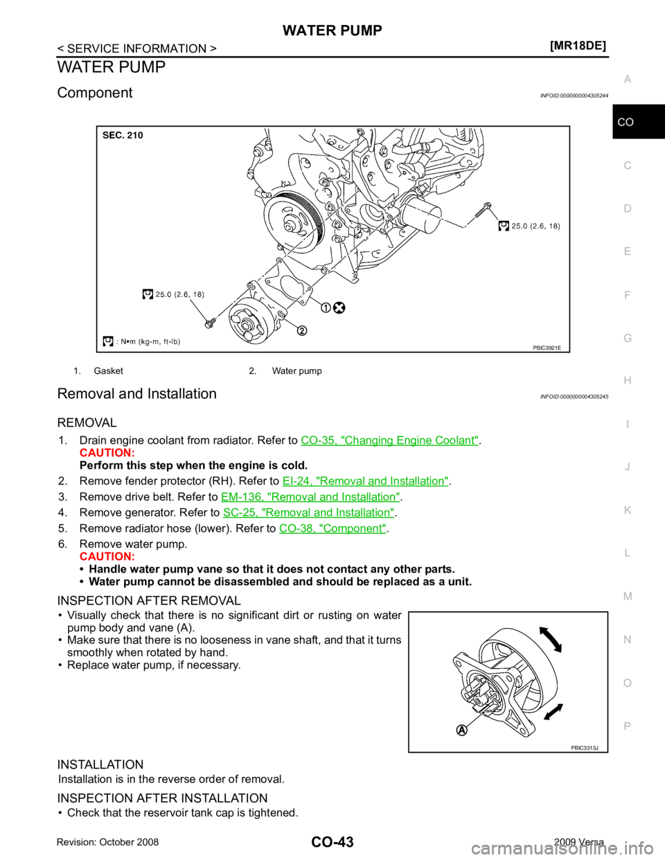
Component INFOID:0000000004305244
Removal and Installation INFOID:0000000004305245
REMOVAL 1. Drain engine coolant from radiator. Refer to CO-35, " Changing Engine Coolant " .
CAUTION:
Perform this step when the engine is cold.
2. Remove fender protector (RH). Refer to EI-24, " Removal and Installation " .
3. Remove drive belt. Refer to EM-136, " Removal and Installation " .
4. Remove generator. Refer to SC-25, " Removal and Installation " .
5. Remove radiator hose (lower). Refer to CO-38, " Component " .
6. Remove water pump. CAUTION:
• Handle water pump vane so that it does not contact any other parts.
• Water pump cannot be disassembled and should be replaced as a unit.
INSPECTION AFTER REMOVAL • Visually check that there is no significant dirt or rusting on water pump body and vane (A).
• Make sure that there is no looseness in vane shaft, and that it turns
smoothly when rotated by hand.
• Replace water pump, if necessary.
INSTALLATION Installation is in the reverse order of removal.
INSPECTION AFTER INSTALLATION • Check that the reservoir tank cap is tightened. 1. Gasket 2. Water pump
PBIC3313J
Page 938 of 4331
Inspection " .
• Start and warm up the engine. Visually check for leaks of engine coolant.
Page 939 of 4331
CO
NP
O
THERMOSTAT
Component INFOID:0000000004305246
Removal and Installation INFOID:0000000004305247
REMOVAL 1. Drain engine coolant from radiator. Refer to CO-35, " Changing Engine Coolant " .
CAUTION:
• Perform this step when engine is cold.
• Never spill engine coolant on drive belt.
2. Remove the air duct (inlet). Refer to EM-139, " Component " .
3. Remove the radiator hose (lower) from the engine. Refer to CO-38, " Component " .
4. Remove water inlet.
5. Remove thermostat.
6. Remove water pump, if necessary. Refer to CO-43 .
7. Remove thermostat housing, if necessary.
INSPECTION AFTER REMOVAL 1. Thermostat housing 2. Water hose (models with oil cooler) 3. Radiator hose (lower)
4. Water inlet 5. Thermostat 6. Rubber ring
7. Gasket A. To oil cooler B. To radiator Engine front
Page 940 of 4331
Inspection " .
• Start and warm up the engine. Visually check for leaks of engine coolant.
Page 941 of 4331

CO
NP
O
WATER OUTLET AND WATER CONTROL VALVE
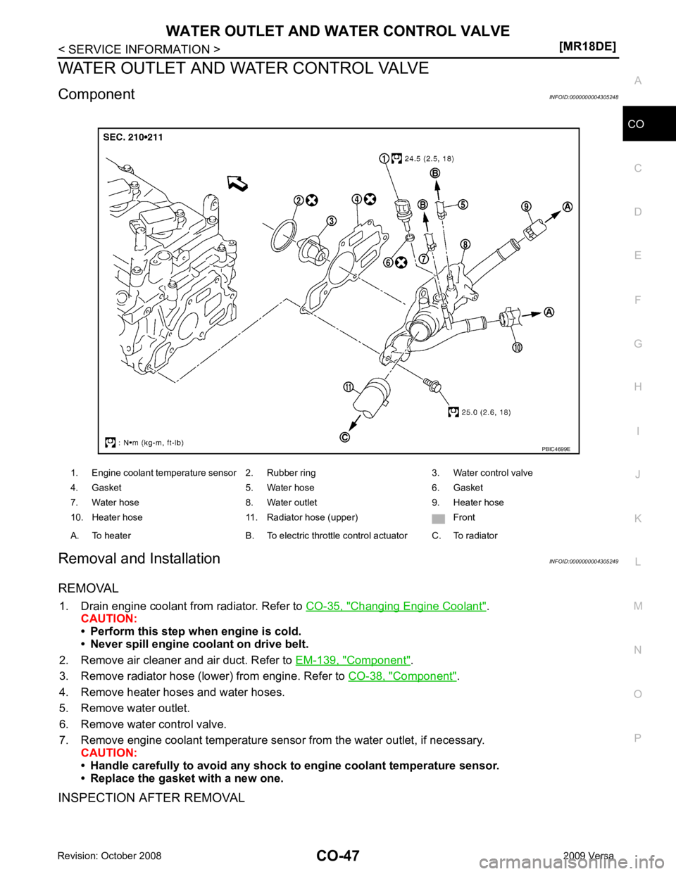
Component INFOID:0000000004305248
Removal and Installation INFOID:0000000004305249
REMOVAL 1. Drain engine coolant from radiator. Refer to CO-35, " Changing Engine Coolant " .
CAUTION:
• Perform this step when engine is cold.
• Never spill engine coolant on drive belt.
2. Remove air cleaner and air duct. Refer to EM-139, " Component " .
3. Remove radiator hose (lower) from engine. Refer to CO-38, " Component " .
4. Remove heater hoses and water hoses.
5. Remove water outlet.
6. Remove water control valve.
7. Remove engine coolant temperature sensor from the water outlet, if necessary. CAUTION:
• Handle carefully to avoid any shock to engine coolant temperature sensor.
• Replace the gasket with a new one.
INSPECTION AFTER REMOVAL 1. Engine coolant temperature sensor 2. Rubber ring 3. Water control valve
4. Gasket 5. Water hose 6. Gasket
7. Water hose 8. Water outlet 9. Heater hose
10. Heater hose 11. Radiator hose (upper) Front
A. To heater B. To electric throttle control actuator C. To radiator
Page 943 of 4331
CO
NP
O
- Install water hoses (3),(5) as shown.
• Electric throttle control actuator (1)
• Clamp (2)
• Water outlet (4)
• Paint mark (A)
• Clamp shall not interfere with the bulged area (B)
• : Engine front
INSPECTION AFTER INSTALLATION • Check for leaks of engine coolant. Refer to CO-35, " Inspection " .
• Start and warm up the engine. Visually check for leaks of engine coolant.
Page 975 of 4331

CVT
N
O P
The ECM has a memory function, which stores the driv
ing condition such as fuel system status, calculated
load value, engine coolant temperature, short term f uel trim, long term fuel trim, engine speed and vehicle
speed at the moment the ECM detects a malfunction.
Data which are stored in the ECM memory, along with the 1st trip DTC, are called 1st trip freeze frame data,
and the data, stored together with the DTC data, are called freeze frame data and displayed on CONSULT-III
or GST. The 1st trip freeze frame data can only be di splayed on the CONSULT-III screen, not on the GST. For
details, refer to EC-604, " CONSULT-III Function (ENGINE) " .
Only one set of freeze frame data (either 1st trip freez e frame data or freeze frame data) can be stored in the
ECM. 1st trip freeze frame data is stored in the ECM me mory along with the 1st trip DTC. There is no priority
for 1st trip freeze frame data, and it is updated each time a different 1st trip DTC is detected. However, once
freeze frame data (2nd trip detection/MIL on) is stored in the ECM memory, 1st trip freeze frame data is no
longer stored. Remember, only one set of freeze frame data can be stored in the ECM. The ECM has the fol-
lowing priorities to update the data.
Both 1st trip freeze frame data and freeze frame data (along with the DTC) are cleared when the ECM mem-
ory is erased.
HOW TO ERASE DTC The diagnostic trouble code can be erased by CONSULT- III, GST or ECM DIAGNOSTIC TEST MODE as
described following.
• If the battery cable is disconnected, the diagnost ic trouble code will be lost within 24 hours.
• When you erase the DTC, using CONSULT-III or GS T is easier and quicker than switching the mode
selector on the ECM.
The following emission-related diagnostic information is cleared from the ECM memory when erasing DTC
related to OBD-II. For details, refer to EC-542, " Emission-related Diagnostic Information " .
• Diagnostic trouble codes (DTC)
• 1st trip diagnostic trouble codes (1st trip DTC)
• Freeze frame data
• 1st trip freeze frame data
• System readiness test (SRT) codes
• Test values
HOW TO ERASE DTC (WITH CONSULT-III)
• If a DTC is displayed for both ECM and TCM, it is necessary to be erased for both ECM and TCM.
1. If the ignition switch stays ON after repair work, be su re to turn ignition switch OFF once. Wait at least 10
seconds and then turn it ON (engine stopped) again.
2. Turn CONSULT-III ON and touch “TRANSMISSION”.
3. Touch “SELF-DIAG RESULTS”.
4. Touch “ERASE”. (The DTC in the TCM will be erased.) Then touch “BACK” twice.
5. Touch “ENGINE”.
6. Touch “SELF-DIAG RESULTS”.
7. Touch “ERASE”. (The DTC in the ECM will be erased.)
HOW TO ERASE DTC (WITH GST)
1. If the ignition switch stays ON after repair work, be su re to turn ignition switch OFF once. Wait at least 10
seconds and then turn it ON (engine stopped) again.
2. Select Mode 4 with GST (Generic Scan Tool). For details, refer to EC-612, " Generic Scan Tool (GST)
Function " .
Malfunction Indicator Lamp (MIL) INFOID:0000000004666879
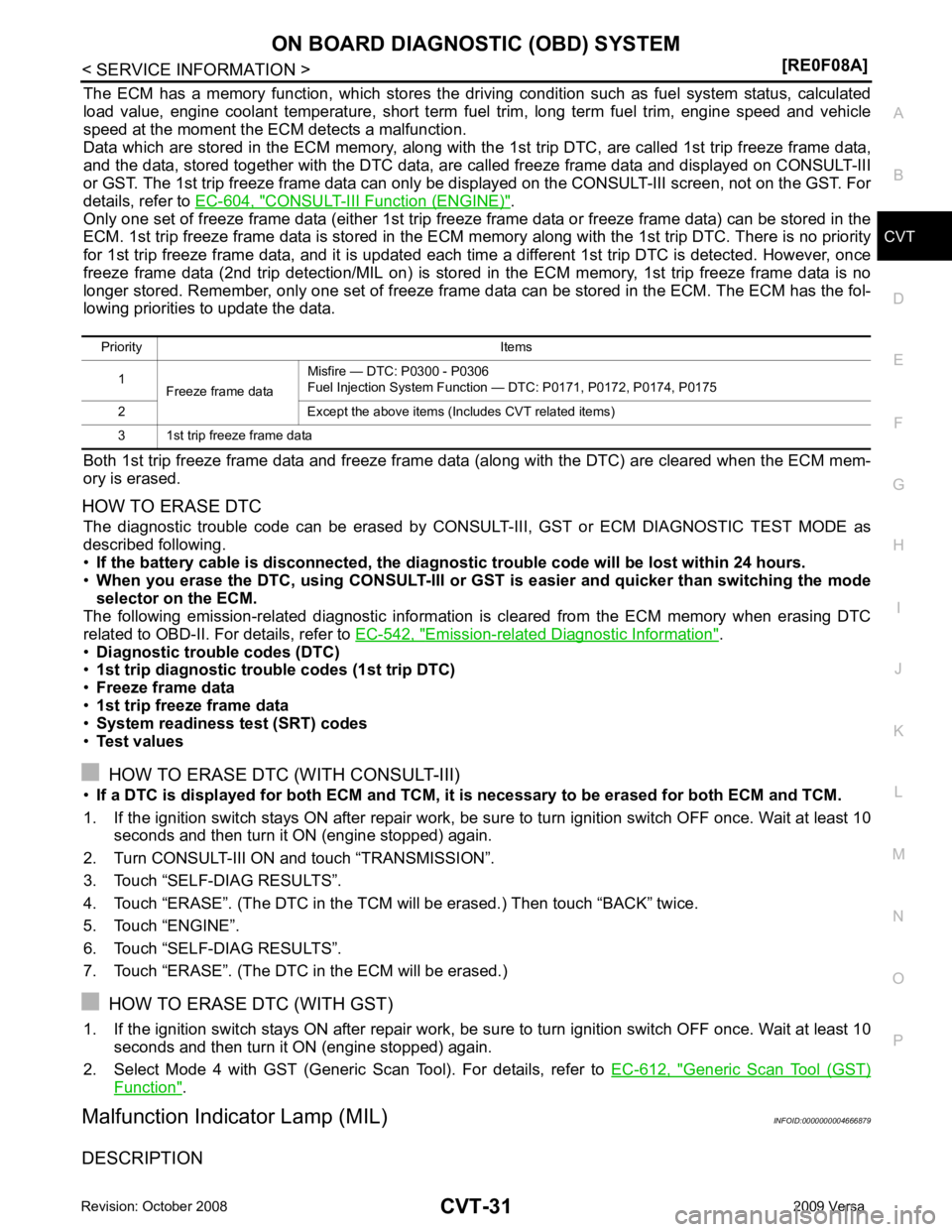
DESCRIPTION Priority Items
1 Freeze frame data Misfire — DTC: P0300 - P0306
Fuel Injection System Function — DTC: P0171, P0172, P0174, P0175
2 Except the above items (Includes CVT related items)
3 1st trip freeze frame data