2009 NISSAN LATIO engine coolant
[x] Cancel search: engine coolantPage 1312 of 4331
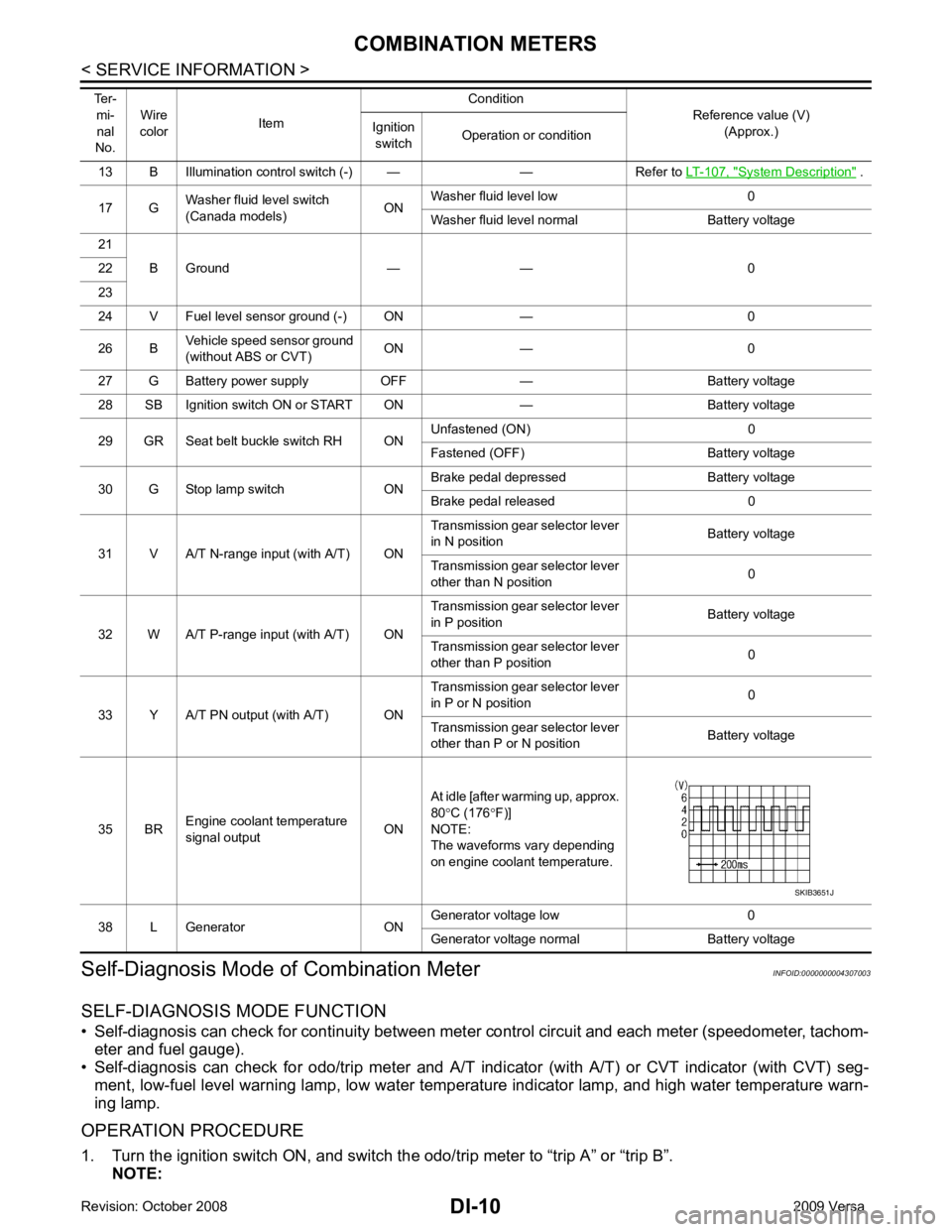
System Description " .
17 G Washer fluid level switch
(Canada models) ONWasher fluid level low 0
Washer fluid level normal Battery voltage
21 B Ground — — 0
22
23
24 V Fuel level sensor ground (-) ON — 0
26 B Vehicle speed sensor ground
(without ABS or CVT) ON — 0
27 G Battery power supply OFF — Battery voltage
28 SB Ignition switch ON or START ON — Battery voltage
29 GR Seat belt buckle switch RH ON Unfastened (ON) 0
Fastened (OFF) Battery voltage
30 G Stop lamp switch ON Brake pedal depressed Battery voltage
Brake pedal released 0
31 V A/T N-range input (with A/T) ON Transmission gear selector lever
in N position Battery voltage
Transmission gear selector lever
other than N position 0
32 W A/T P-range input (with A/T) ON Transmission gear selector lever
in P position Battery voltage
Transmission gear selector lever
other than P position 0
33 Y A/T PN output (with A/T) ON Transmission gear selector lever
in P or N position 0
Transmission gear selector lever
other than P or N position Battery voltage
35 BR Engine coolant temperature
signal output ONAt idle [after warming up, approx.
80 °C (176 °F)]
NOTE:
The waveforms vary depending
on engine coolant temperature.
38 L Generator ON Generator voltage low 0
Generator voltage normal Battery voltage
Ter-
mi-
nal
No. Wire
color Item Condition
Reference value (V)
(Approx.)
Ignition
switch Operation or condition
Page 1314 of 4331
![NISSAN LATIO 2009 Service Repair Manual CONSULT-III display Malfunction Reference page
CAN COMM CIRC [U1000] Malfunction is detected in CAN communication lines.
CAUTION:
Even when there is no malfunct ion on CAN communication system, mal-
f NISSAN LATIO 2009 Service Repair Manual CONSULT-III display Malfunction Reference page
CAN COMM CIRC [U1000] Malfunction is detected in CAN communication lines.
CAUTION:
Even when there is no malfunct ion on CAN communication system, mal-
f](/manual-img/5/57359/w960_57359-1313.png)
CONSULT-III display Malfunction Reference page
CAN COMM CIRC [U1000] Malfunction is detected in CAN communication lines.
CAUTION:
Even when there is no malfunct ion on CAN communication system, mal-
function may be misinterpreted when battery has low voltage (when main-
taining 7 - 8 V for about 2 seconds) or 10A fuse [No. 14, located in the fuse
block (J/B)] is removed. DI-18VEHICLE SPEED CIRC [B2205]
Malfunction is detected when an erroneous speed signal is input.
CAUTION:
Even when there is no malfunction on speed signal system, malfunctions
may be misinterpreted when battery has low voltage (when maintaining 7
- 8 V for about 2 seconds). DI-15Display item [Unit]
MAIN
SIGNALS SELECTION
FROM MENU Contents
SPEED METER [km/h] X X The value of vehicle speed sign
al, which is input from ABS ac-
tuator and electric unit (control unit).
SPEED OUTPUT [km/h] X X The value of vehicle speed signal, which is transmitted to each
unit with CAN communication.
TACHO METER [rpm] X X The value of engine speed signal, which is input from ECM.
W TEMP METER [ °C] X X The value of engine coolant temperature signal, which is input
from ECM.
FUEL METER [lit.] X X The value, which processes a resistance signal from fuel
gauge.
DISTANCE [km] X X The value, which is calculated by vehicle speed signal from
ABS actuator and electric unit (con trol unit), fuel gauge and fuel
consumption signal from ECM.
FUEL W/L [ON/OFF] X X Indicates [ON/OFF] condition of low-fuel warning lamp.
C-ENG W/L [ON/OFF] X Indicates [ON/OFF] condition of malfunction indicator lamp
(MIL).
AIR PRES W/L X Indicates [ON/OFF] condition of low tire pressure warning lamp.
SEAT BELT W/L X Indicates [ON/OFF] condition of seat belt warning lamp.
BUZZER [ON/OFF] X X Indicates [ON/ OFF] condition of buzzer.
DOOR W/L [ON/OFF] X Indicates [ON/OFF] condition of door warning lamp.
HI-BEAM IND [ON/OFF] X Indicat es [ON/OFF] condition of high beam indicator lamp.
Page 1369 of 4331
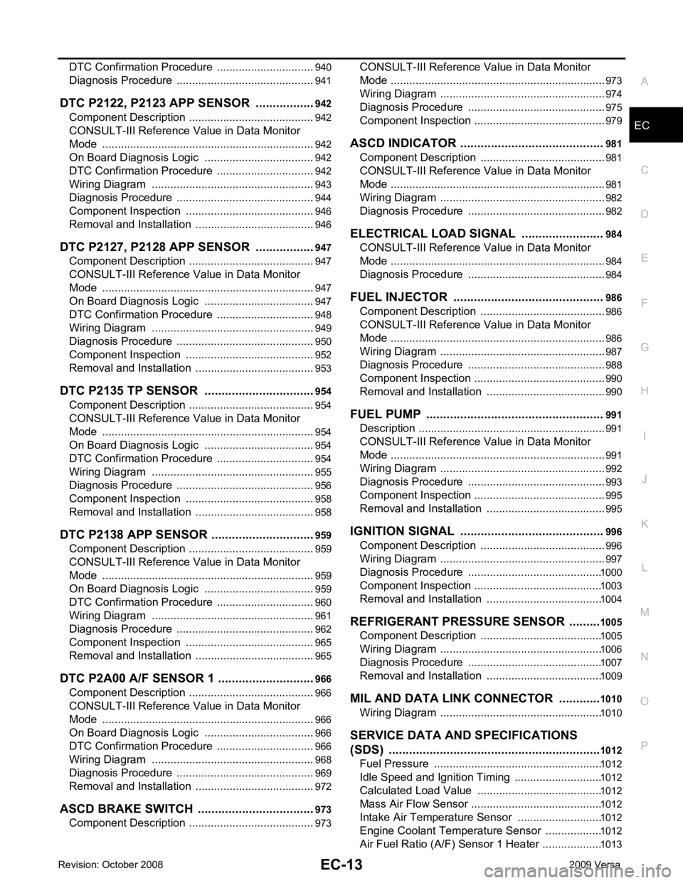
EC
A
N
O P
DTC Confirmation Procedure ..............................
..
940
Diagnosis Procedure ........................................... ..941
DTC P2122, P2123 APP SENSOR ................ ..942
Component Description ....................................... ..942
CONSULT-III Refe rence Value in Data Monitor
Mode ................................................................... ..
942
On Board Diagnosis Logic .................................. ..942
DTC Confirmation Procedure .............................. ..942
Wiring Diagram ................................................... ..943
Diagnosis Procedure ........................................... ..944
Component Inspection ........................................ ..946
Removal and Installation .......................................946
DTC P2127, P2128 APP SENSOR ................ ..947
Component Description ....................................... ..947
CONSULT-III Refe rence Value in Data Monitor
Mode ................................................................... ..
947
On Board Diagnosis Logic .................................. ..947
DTC Confirmation Procedure .............................. ..948
Wiring Diagram ................................................... ..949
Diagnosis Procedure ........................................... ..950
Component Inspection ........................................ ..952
Removal and Installation .......................................953
DTC P2135 TP SENSOR ............................... ..954
Component Description ....................................... ..954
CONSULT-III Refe rence Value in Data Monitor
Mode ................................................................... ..
954
On Board Diagnosis Logic .................................. ..954
DTC Confirmation Procedure .............................. ..954
Wiring Diagram ................................................... ..955
Diagnosis Procedure ........................................... ..956
Component Inspection ........................................ ..958
Removal and Installation .......................................958
DTC P2138 APP SENSOR ............................. ..959
Component Description ....................................... ..959
CONSULT-III Refe rence Value in Data Monitor
Mode ................................................................... ..
959
On Board Diagnosis Logic .................................. ..959
DTC Confirmation Procedure .............................. ..960
Wiring Diagram ................................................... ..961
Diagnosis Procedure ........................................... ..962
Component Inspection ........................................ ..965
Removal and Installation .......................................965
DTC P2A00 A/F SENSOR 1 ........................... ..966
Component Description ....................................... ..966
CONSULT-III Refe rence Value in Data Monitor
Mode ................................................................... ..
966
On Board Diagnosis Logic .................................. ..966
DTC Confirmation Procedure .............................. ..966
Wiring Diagram ................................................... ..968
Diagnosis Procedure ........................................... ..969
Removal and Installation .......................................972
ASCD BRAKE SWITCH ................................. ..973
Component Description ....................................... ..973 CONSULT-III Reference Va
lue in Data Monitor
Mode .................................................................... ..
973
Wiring Diagram .................................................... ..974
Diagnosis Procedure ........................................... ..975
Component Inspection ......................................... ..979
ASCD INDICATOR .......................................... 981
Component Description ....................................... ..981
CONSULT-III Reference Va lue in Data Monitor
Mode .................................................................... ..
981
Wiring Diagram .................................................... ..982
Diagnosis Procedure ........................................... ..982
ELECTRICAL LOAD SIGNAL ........................ 984
CONSULT-III Reference Va lue in Data Monitor
Mode .................................................................... ..
984
Diagnosis Procedure ........................................... ..984
FUEL INJECTOR ............................................ 986
Component Description ....................................... ..986
CONSULT-III Reference Va lue in Data Monitor
Mode .................................................................... ..
986
Wiring Diagram .................................................... ..987
Diagnosis Procedure ........................................... ..988
Component Inspection ......................................... ..990
Removal and Installation ..................................... ..990
FUEL PUMP .................................................... 991
Description ........................................................... ..991
CONSULT-III Reference Va lue in Data Monitor
Mode .................................................................... ..
991
Wiring Diagram .................................................... ..992
Diagnosis Procedure ........................................... ..993
Component Inspection ......................................... ..995
Removal and Installation ..................................... ..995
IGNITION SIGNAL .......................................... 996
Component Description ....................................... ..996
Wiring Diagram .................................................... ..997
Diagnosis Procedure ........................................... 1000
Component Inspection ......................................... 1003
Removal and Installation ..................................... 1004
REFRIGERANT PRESSURE SENSOR ......... 1005
Component Description ....................................... 1005
Wiring Diagram .................................................... 1006
Diagnosis Procedure ........................................... 1007
Removal and Installation ..................................... 1009
MIL AND DATA LINK CONNECTOR ............ 1010
Wiring Diagram .................................................... 1010
SERVICE DATA AND SPECIFICATIONS
(SDS) .............................................................. 1012
Fuel Pressure ...................................................... 1012
Idle Speed and Ignition Timing ............................ 1012
Calculated Load Value ........................................ 1012
Mass Air Flow Sensor .......................................... 1012
Intake Air Temperature Sensor ........................... 1012
Engine Coolant Temperature Sensor .................. 1012
Air Fuel Ratio (A/F) Sensor 1 Heater ................... 1013
Page 1377 of 4331
EC
A
N
O P
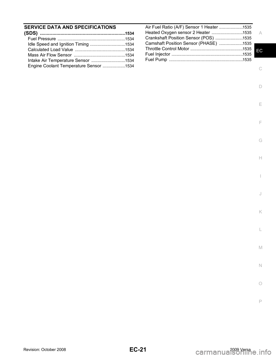
SERVICE DATA AND SPECIFICATIONS
(SDS) .............................................................. 1534
Fuel Pressure ...................................................... 1534
Idle Speed and Ignition Timing ............................ 1534
Calculated Load Value ........................................ 1534
Mass Air Flow Sensor ......................................... 1534
Intake Air Temperature Sensor ........................... 1534
Engine Coolant Temperature Sensor .................. 1534Air Fuel Ratio (A/F) Sensor 1 Heater ...................
1535
Heated Oxygen sensor 2 Heater ......................... 1535
Crankshaft Position Sensor (POS) ...................... 1535
Camshaft Position Sensor (PHASE) ................... 1535
Throttle Control Motor .......................................... 1535
Fuel Injector ......................................................... 1535
Fuel Pump ........................................................... 1535
Page 1393 of 4331
EC
NP
O
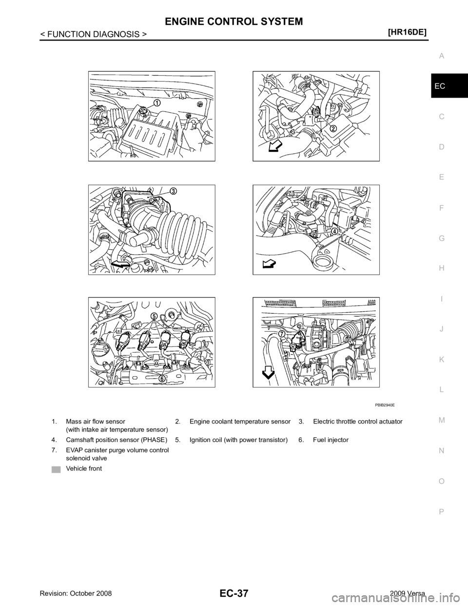
1. Mass air flow sensor
(with intake air temperature sensor) 2. Engine coolant temperature sensor 3. Electric throttle control actuator
4. Camshaft position sensor (PHASE) 5. Ignition coil (with power transistor) 6. Fuel injector
7. EVAP canister purge volume control solenoid valve
Vehicle front
Page 1397 of 4331
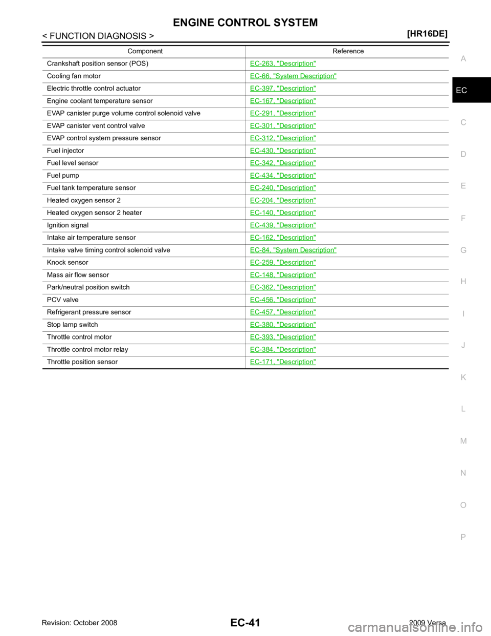
EC
NP
O
Crankshaft position sensor (POS)
EC-263, " Description "
Cooling fan motor
EC-66, " System Description "
Electric throttle control actuator
EC-397, " Description "
Engine coolant temperature sensor
EC-167, " Description "
EVAP canister purge volume control solenoid valve
EC-291, " Description "
EVAP canister vent control valve
EC-301, " Description "
EVAP control system pressure sensor
EC-312, " Description "
Fuel injector
EC-430, " Description "
Fuel level sensor
EC-342, " Description "
Fuel pump
EC-434, " Description "
Fuel tank temperature sensor
EC-240, " Description "
Heated oxygen sensor 2
EC-204, " Description "
Heated oxygen sensor 2 heater
EC-140, " Description "
Ignition signal
EC-439, " Description "
Intake air temperature sensor
EC-162, " Description "
Intake valve timing control solenoid valve
EC-84, " System Description "
Knock sensor
EC-259, " Description "
Mass air flow sensor
EC-148, " Description "
Park/neutral position switch
EC-362, " Description "
PCV valve
EC-456, " Description "
Refrigerant pressure sensor
EC-457, " Description "
Stop lamp switch
EC-380, " Description "
Throttle control motor
EC-393, " Description "
Throttle control motor relay
EC-384, " Description "
Throttle position sensor
EC-171, " Description "Component Reference
Page 1399 of 4331
EC
NP
O
*3: ECM determines the start signal status by the signals of engine speed and battery voltage.
SYSTEM DESCRIPTION The amount of fuel injected from the fuel injector is determined by the ECM. The ECM controls the length of
time the valve remains open (injection pulse duration). T he amount of fuel injected is a program value in the
ECM memory. The program value is preset by engi ne operating conditions. These conditions are determined
by input signals (for engine speed and intake air) from t he crankshaft position sensor (POS), camshaft position
sensor (PHASE) and the mass air flow sensor.
VARIOUS FUEL INJECTION INCREASE/DECREASE COMPENSATION In addition, the amount of fuel injected is compens ated to improve engine performance under various operat-
ing conditions as listed below.
• During warm-up
• When starting the engine
• During acceleration
• Hot-engine operation
• When selector lever is changed from N to D (A/T models)
• High-load, high-speed operation
• During deceleration
• During high engine speed operation
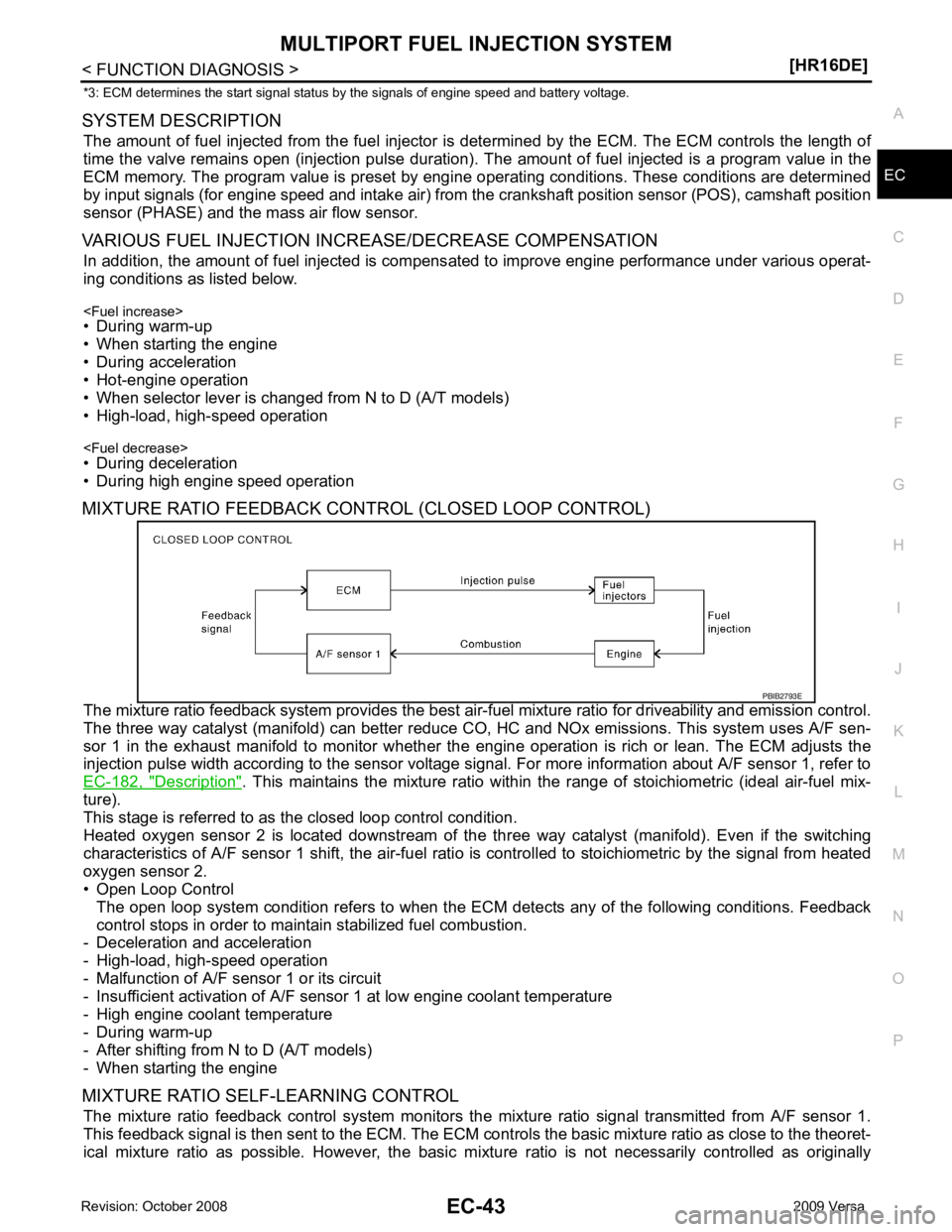
MIXTURE RATIO FEEDBACK CONTROL (CLOSED LOOP CONTROL)
The mixture ratio feedback system prov ides the best air-fuel mixture ratio for driveability and emission control.
The three way catalyst (manifold) can better reduce CO, HC and NOx emissions. This system uses A/F sen-
sor 1 in the exhaust manifold to monitor whether the engine operation is rich or lean. The ECM adjusts the
injection pulse width according to the sensor voltage si gnal. For more information about A/F sensor 1, refer to
EC-182, " Description " . This maintains the mixture ratio within t
he range of stoichiometric (ideal air-fuel mix-
ture).
This stage is referred to as the closed loop control condition.
Heated oxygen sensor 2 is located downstream of the th ree way catalyst (manifold). Even if the switching
characteristics of A/F sensor 1 shift, the air-fuel rati o is controlled to stoichiometric by the signal from heated
oxygen sensor 2.
• Open Loop Control
The open loop system condition refers to when the EC M detects any of the following conditions. Feedback
control stops in order to maintain stabilized fuel combustion.
- Deceleration and acceleration
- High-load, high-speed operation
- Malfunction of A/F sensor 1 or its circuit
- Insufficient activation of A/F sensor 1 at low engine coolant temperature
- High engine coolant temperature
- During warm-up
- After shifting from N to D (A/T models)
- When starting the engine
MIXTURE RATIO SELF-LEARNING CONTROL The mixture ratio feedback control system monitors the mixture ratio signal transmitted from A/F sensor 1.
This feedback signal is then sent to the ECM. The ECM cont rols the basic mixture ratio as close to the theoret-
ical mixture ratio as possible. However, the basic mi xture ratio is not necessarily controlled as originally
Page 1401 of 4331
![NISSAN LATIO 2009 Service Repair Manual MULTIPORT FUEL INJECTION SYSTEM
EC-45
< FUNCTION DIAGNOSIS >
[HR16DE] C
D E
F
G H
I
J
K L
M A EC
NP
O
Component Parts Location
INFOID:0000000004780012
1. Ignition coil (with power transistor) and spa NISSAN LATIO 2009 Service Repair Manual MULTIPORT FUEL INJECTION SYSTEM
EC-45
< FUNCTION DIAGNOSIS >
[HR16DE] C
D E
F
G H
I
J
K L
M A EC
NP
O
Component Parts Location
INFOID:0000000004780012
1. Ignition coil (with power transistor) and spa](/manual-img/5/57359/w960_57359-1400.png)
MULTIPORT FUEL INJECTION SYSTEM
EC-45
< FUNCTION DIAGNOSIS >
[HR16DE] C
D E
F
G H
I
J
K L
M A EC
NP
O
Component Parts Location
INFOID:0000000004780012
1. Ignition coil (with power transistor) and spark plug 2. Intake valve timing control solenoid
valve 3. Refrigerant pressure sensor
4. Knock sensor 5. Fuel injector 6. Cooling fan motor
7. Camshaft position sensor (PHASE) 8. IPDM E/R 9. ECM
10. Mass air flow sensor (with intake air temperature sensor) 11. Engine coolant temperature sensor 12. Electric throttle control actuator
(with built in throttle position sensor
and throttle control motor)
13. EVAP canister purge volume control solenoid valve PBIB2939E