2009 NISSAN LATIO light
[x] Cancel search: lightPage 2984 of 4331

EM
NP
O
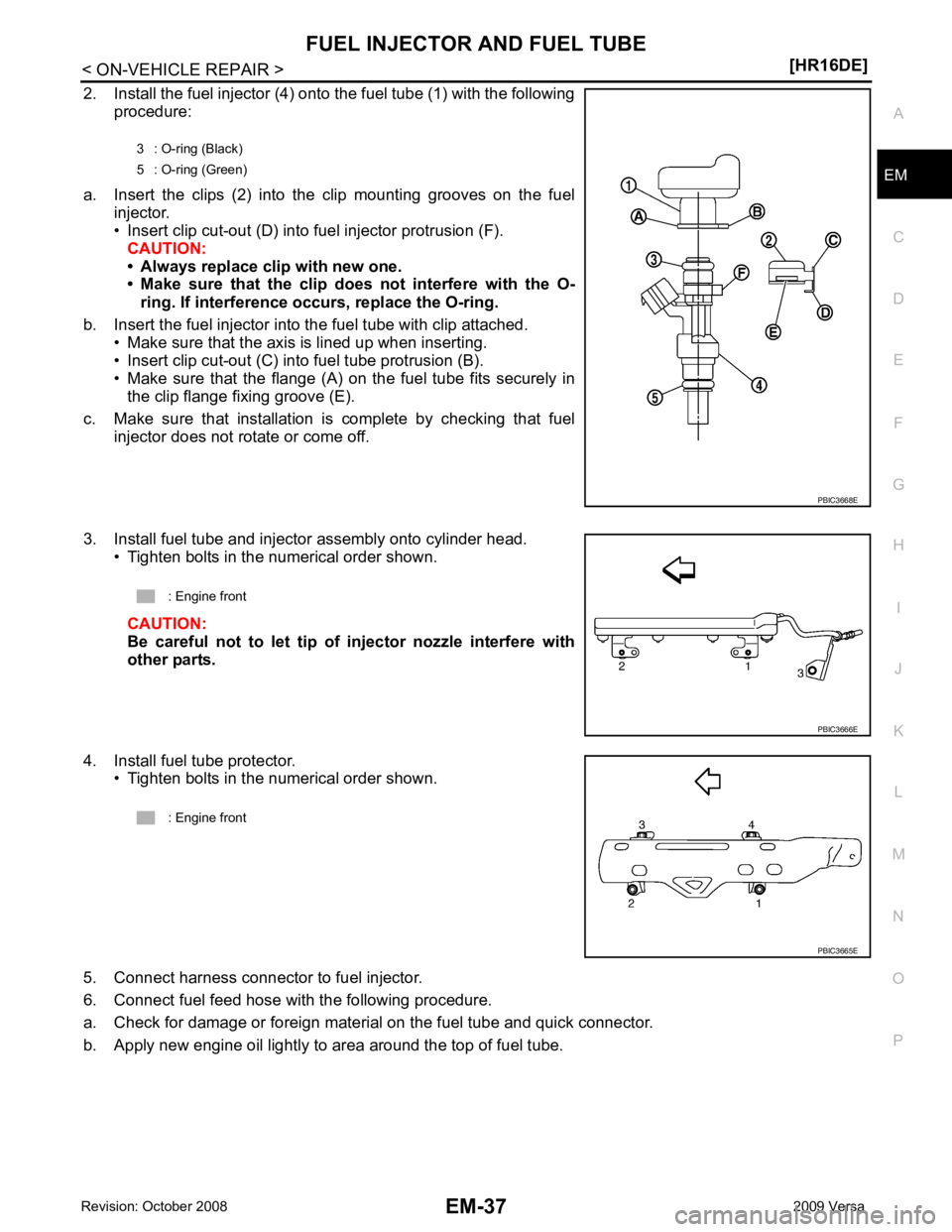
2. Install the fuel injector (4) onto the fuel tube (1) with the following
procedure:
a. Insert the clips (2) into the clip mounting grooves on the fuel injector.
• Insert clip cut-out (D) into fuel injector protrusion (F). CAUTION:
• Always replace clip with new one.
• Make sure that the clip do es not interfere with the O-
ring. If interference occurs, replace the O-ring.
b. Insert the fuel injector into the fuel tube with clip attached. • Make sure that the axis is lined up when inserting.
• Insert clip cut-out (C) into fuel tube protrusion (B).
• Make sure that the flange (A) on the fuel tube fits securely in the clip flange fixing groove (E).
c. Make sure that installation is complete by checking that fuel injector does not rotate or come off.
3. Install fuel tube and injector assembly onto cylinder head. • Tighten bolts in the numerical order shown.
CAUTION:
Be careful not to let tip of injector nozzle interfere with
other parts.
4. Install fuel tube protector. • Tighten bolts in the numerical order shown.
5. Connect harness connector to fuel injector.
6. Connect fuel feed hose with the following procedure.
a. Check for damage or foreign material on the fuel tube and quick connector.
b. Apply new engine oil lightly to area around the top of fuel tube. 3 : O-ring (Black)
5 : O-ring (Green)
Page 2985 of 4331
![NISSAN LATIO 2009 Service Repair Manual EM-38< ON-VEHICLE REPAIR >
[HR16DE]
FUEL INJECTOR AND FUEL TUBE
c. Align center to insert quick connector straightly into fuel tube. • Insert quick connector to fuel tube until the top spoo NISSAN LATIO 2009 Service Repair Manual EM-38< ON-VEHICLE REPAIR >
[HR16DE]
FUEL INJECTOR AND FUEL TUBE
c. Align center to insert quick connector straightly into fuel tube. • Insert quick connector to fuel tube until the top spoo](/manual-img/5/57359/w960_57359-2984.png)
EM-38< ON-VEHICLE REPAIR >
[HR16DE]
FUEL INJECTOR AND FUEL TUBE
c. Align center to insert quick connector straightly into fuel tube. • Insert quick connector to fuel tube until the top spool on fueltube is inserted completely and the 2nd level spool is posi-
tioned slightly below quick connector bottom end.
CAUTION:
• Hold “A” position shown when inserting fuel tube into
quick connector.
• Carefully align center to avoid inclined insertion to pre-
vent damage to O-ring inside quick connector.
• Insert until you hear a “click” sound and actually feel
the engagement.
• To avoid misidentification of engagement with a similar sound, be sure to pe rform the next step.
d. Before clamping fuel feed hose with hose clamp, pull quick connector hard by hand holding “A” position.
Make sure it is completely engaged (connected) so that it does not come out from fuel tube.
e. Install quick connector cap (1) to quick connector connection. • Install quick connector cap with the side arrow facing quick
connector side (fuel feed hose side).
CAUTION:
• Make sure that the quick connector and fuel tube are
securely engaged with the quick connector cap mount-
ing groove.
• Quick connector may not be connected correctly if quick connector cap cannot be installed easily. Remove
the quick connector cap, and then check the connection
of quick connector again.
f. Install fuel feed hose to hose clamp.
7. Installation of the remaining components is in the reverse order of removal.
Inspection INFOID:0000000004784288
INSPECTION AFTER INSTALLATION
Check on Fuel Leakage
1. Turn ignition switch “ON” (with the engine stopped). With fuel pressure applied to fuel piping, make sure
there are no fuel leaks at connection points.
NOTE:
Use mirrors for checking at points out of clear sight.
2. Start the engine. With engine speed increased, make su re again that there are no fuel leaks at connection
points.
CAUTION:
Never touch the engine immediately after it is stopped, as the engine becomes extremely hot. KBIA0272E
PBIC3664E
Page 2991 of 4331
![NISSAN LATIO 2009 Service Repair Manual EM-44< ON-VEHICLE REPAIR >
[HR16DE]
OIL PAN (UPPER) AND OIL STRAINER
c. Apply a continuous bead of liquid gasket (D) with Tool to areas shown.
Use Genuine Silicone RTV Seal ant or equ NISSAN LATIO 2009 Service Repair Manual EM-44< ON-VEHICLE REPAIR >
[HR16DE]
OIL PAN (UPPER) AND OIL STRAINER
c. Apply a continuous bead of liquid gasket (D) with Tool to areas shown.
Use Genuine Silicone RTV Seal ant or equ](/manual-img/5/57359/w960_57359-2990.png)
EM-44< ON-VEHICLE REPAIR >
[HR16DE]
OIL PAN (UPPER) AND OIL STRAINER
c. Apply a continuous bead of liquid gasket (D) with Tool to areas shown.
Use Genuine Silicone RTV Seal ant or equivalent. Refer to
GI-42, " Recommended Chemical
Product and Sealant " .
CAUTION:
Installation should be done within 5 minutes after coating.
d. Tighten bolts in the numerical order shown. CAUTION:
Avoid misalignment of both oil pan gasket and O-ring.
• The bolts are different according to the installation position. Follow the numbers shown.
2. Install rear oil seal with the following procedure: CAUTION:
• The installation of rear oil seal should be co mpleted within 5 minutes after installing oil pan
(upper).
• Do not touch oil seal lip.
a. Wipe off any liquid gasket protruding to the rear oil seal mounting part of oil pan (upper) and cylinder block using a spatula.
b. Apply the liquid gasket lightly to entire outside area of new rear oil seal. Use Genuine Silicone RTV Seal ant or equivalent. Refer to GI-42, " Recommended Chemical Prod-
uct and Sealant " .
c. Press-fit the rear oil seal using a drift with outer diameter 113 mm (4.45 in) and inner diameter 90 mm (3.54 in) (A). A : 2 mm (0.07 in) protruded to outside
B : 2 mm (0.07 in) protruded to rear oil seal mounting side
C : 5.5 - 7.5 mm (0.216 - 0.295 in)
E : 4.0 - 5.0 mm (0.157 - 0.196 in) dia.
: Engine front
: Engine out side
Tool number : WS39930000 ( — ) AWBIA0790ZZ
: Engine front
M8 × 179 mm (7.09 in) : No. 9, 10
M8 × 25 mm (0.98 in) : No. 3, 4, 7, 8
M8 × 90 mm (3.54 in) : No. 1, 2, 5, 6 ALBIA0627ZZ
PBIC3660E
Page 2998 of 4331

EM
NP
O
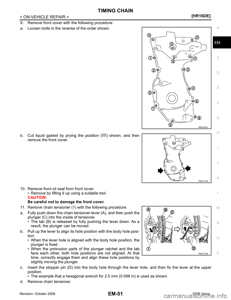
9. Remove front cover with the following procedure:
a. Loosen bolts in the reverse of the order shown.
b. Cut liquid gasket by prying the position ( ) shown, and then remove the front cover.
10. Remove front oil seal from front cover. • Remove by lifting it up using a suitable tool.
CAUTION:
Be careful not to damage the front cover.
11. Remove chain tensioner (1) with the following procedure.
a. Fully push down the chain tensioner lever (A), and then push the plunger (C) into the inside of tensioner.
• The tab (B) is released by fully pushing the lever down. As a result, the plunger can be moved.
b. Pull up the lever to align its hole position with the body hole posi- tion.
• When the lever hole is aligned with the body hole position, the
plunger is fixed.
• When the protrusion parts of the plunger ratchet and the tab face each other, both hole positions are not aligned. At that
time, correctly engage them and align these hole positions by
slightly moving the plunger.
c. Insert the stopper pin (D) into the body hole thr ough the lever hole, and then fix the lever at the upper
position.
• The example that a hexagonal wrench for 2.5 mm (0.098 in) is used as shown.
d. Remove chain tensioner. PBIC3712E
PBIC3713E
Page 3012 of 4331

EM
NP
O
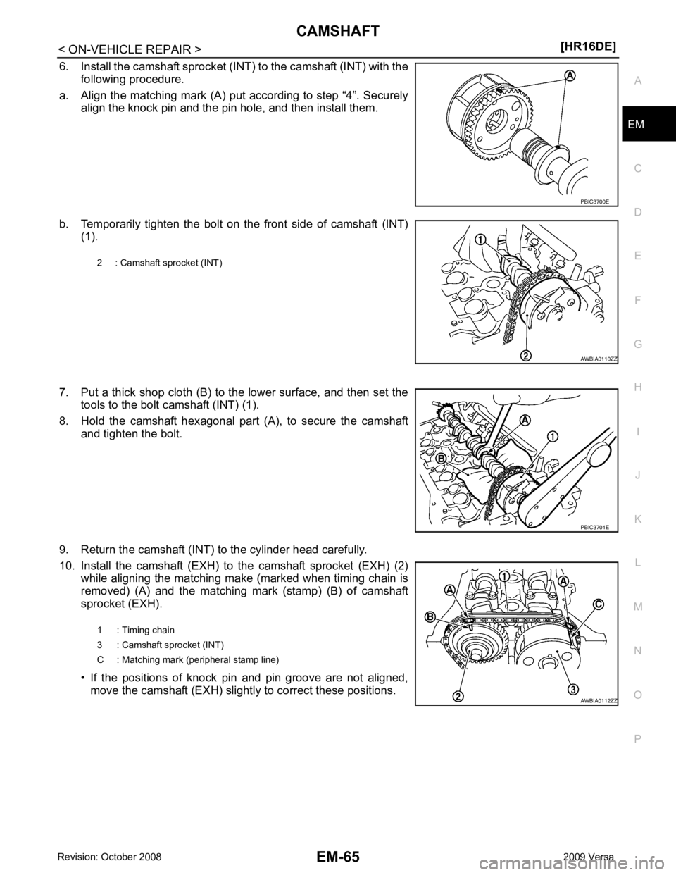
6. Install the camshaft sprocket (INT) to the camshaft (INT) with the
following procedure.
a. Align the matching mark (A) put according to step “4”. Securely align the knock pin and the pin hole, and then install them.
b. Temporarily tighten the bolt on the front side of camshaft (INT) (1).
7. Put a thick shop cloth (B) to the lower surface, and then set the tools to the bolt camshaft (INT) (1).
8. Hold the camshaft hexagonal part (A), to secure the camshaft and tighten the bolt.
9. Return the camshaft (INT) to the cylinder head carefully.
10. Install the camshaft (EXH) to the camshaft sprocket (EXH) (2) while aligning the matching make (marked when timing chain is
removed) (A) and the matching mark (stamp) (B) of camshaft
sprocket (EXH).
• If the positions of knock pin and pin groove are not aligned, move the camshaft (EXH) slightly to correct these positions. PBIC3701E
Page 3014 of 4331
![NISSAN LATIO 2009 Service Repair Manual CAMSHAFT
EM-67
< ON-VEHICLE REPAIR >
[HR16DE] C
D E
F
G H
I
J
K L
M A EM
NP
O
14. Install timing chain with the following procedure.
• Install by aligning matching marks on each sprocket and NISSAN LATIO 2009 Service Repair Manual CAMSHAFT
EM-67
< ON-VEHICLE REPAIR >
[HR16DE] C
D E
F
G H
I
J
K L
M A EM
NP
O
14. Install timing chain with the following procedure.
• Install by aligning matching marks on each sprocket and](/manual-img/5/57359/w960_57359-3013.png)
CAMSHAFT
EM-67
< ON-VEHICLE REPAIR >
[HR16DE] C
D E
F
G H
I
J
K L
M A EM
NP
O
14. Install timing chain with the following procedure.
• Install by aligning matching marks on each sprocket and tim-ing chain.
• If these matching marks are not aligned, rotate the camshaft
slightly to correct the position.
CAUTION:
• Check matching mark positi on of each sprocket and tim-
ing chain again after instal ling the timing chain, keep
matching marks aligned by holding them with a hand.
• To avoid skipped teeth, never rotate crankshaft and cam-
shaft until front cover is installed.
15. Install timing chain tension guide (2) and timing chain slack guide (1).
16. Install chain tensioner (1). • Fix the plunger at the most compressed position using a stop-per pin (A), and then install it.
• Securely pull out the stopper pin after installing the chain ten-
sioner.
17. Check matching mark position of timing chain and each sprocket again. A : Dark blue link
B : Matching mark (stamp)
C : Orange link
D : Matching mark (stamp)
E : Crankshaft key (point straight up)
F : Matching mark (peripheral stamp line)
G : Dark blue link PBIC3721E
PBIC3714E
PBIC3722E
Page 3024 of 4331

EM
NP
O
FRONT OIL SEAL : Remo
val and Installation INFOID:0000000004784303
REMOVAL 1. Remove the following parts: • Front fender protector (RH): Refer to EI-24, " Removal and Installation " .
• Drive belt: Refer to EM-15, " Removal and Installation " .
• Crankshaft pulley: Refer to EM-49, " Exploded View " .
2. Remove front oil seal using a suitable tool. CAUTION:
Be careful not to damage fron t timing chain case and crankshaft.
INSTALLATION 1. Apply new engine oil to both oil seal lip and dust seal lip of new front oil seal.
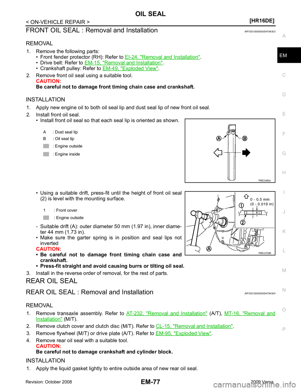
2. Install front oil seal. • Install front oil seal so that each seal lip is oriented as shown.
• Using a suitable drift, press-fit until the height of front oil seal (2) is level with the mounting surface.
- Suitable drift (A): outer diameter 50 mm (1.97 in), inner diame- ter 44 mm (1.73 in).
• Make sure the garter spring is in position and seal lips not
inverted
CAUTION:
• Be careful not to damage front timing chain case and
crankshaft.
• Press-fit straight and avoid cau sing burrs or tilting oil seal.
3. Install in the reverse order of removal, for the rest of parts.
REAR OIL SEAL
REAR OIL SEAL : Removal and Installation INFOID:0000000004784304
REMOVAL 1. Remove transaxle assembly. Refer to AT-232, " Removal and Installation " (A/T),
MT-16, " Removal and
Installation " (M/T).
2. Remove clutch cover and clutch disc (M/T). Refer to CL-15, " Removal and Installation " .
3. Remove flywheel (M/T) or drive plate (A/T). Refer to EM-95, " Exploded View " .
4. Remove rear oil seal with a suitable tool. CAUTION:
Be careful not to damage crankshaft and cylinder block.
INSTALLATION 1. Apply the liquid gasket lightly to entire outside area of new rear oil seal. A : Dust seal lip
B : Oil seal lip
: Engine outside
: Engine inside
Page 3034 of 4331
![NISSAN LATIO 2009 Service Repair Manual CYLINDER HEAD
EM-87
< ON-VEHICLE REPAIR >
[HR16DE] C
D E
F
G H
I
J
K L
M A EM
NP
O
d. Using suitable tool or valve seat grinder, finish seat to the speci-
fied dimensions. Refer to EM-119, " Cylinder NISSAN LATIO 2009 Service Repair Manual CYLINDER HEAD
EM-87
< ON-VEHICLE REPAIR >
[HR16DE] C
D E
F
G H
I
J
K L
M A EM
NP
O
d. Using suitable tool or valve seat grinder, finish seat to the speci-
fied dimensions. Refer to EM-119, " Cylinder](/manual-img/5/57359/w960_57359-3033.png)
CYLINDER HEAD
EM-87
< ON-VEHICLE REPAIR >
[HR16DE] C
D E
F
G H
I
J
K L
M A EM
NP
O
d. Using suitable tool or valve seat grinder, finish seat to the speci-
fied dimensions. Refer to EM-119, " Cylinder Head " .
CAUTION:
When using the valve seat cutt er, firmly grip cutter handle
with both hands. Then, press on the contacting surface all
around the circumference to cu t in a single drive. Improper
pressure on with cutter or cu tting many different times may
result in stage valve seat.
e. Using compound, grind to adjust valve fitting.
f. Check again for normal contact. Refer to EM-82, " Disassembly and Assembly " .
3. Install valve oil seal. • Install with Tool (A) to match dimension as shown.
4. Install valve spring seat.
5. Install valve. • Install larger diameter to intake side.
6. Install valve spring. NOTE:
It can be installed in either direction.
7. Install valve spring retainer.
8. Install valve collet. • Compress valve spring with Tool (A). Install valve collet with amagnet hand (B).
CAUTION:
Be careful not to damage valve lifter holes.
• Tap valve stem edge lightly with a plastic hammer after instal-
lation to check its installed condition.
9. Install valve lifter.
10. Install spark plug with a suitable tool. SEM934C
Height “H” : 13.2 - 13.8 mm (0.520 - 0.543 in)
Tool number : KV10115600 (J-38958) PBIC3211J
Tool number : KV10116200 (J-26336-B)
: KV10115900 (J-26336-20)
: KV10109220 ( — ) PBIC3727E