Page 704 of 4331
VEHICLE SECURITY (THEFT WARNING) SYSTEM
BL-243
< SERVICE INFORMATION >
C
D E
F
G H
J
K L
M A
B BL
N
O P 1.
CHECK DOOR SWITCHES INPUT SIGNAL
With CONSULT-III
Check door switches ("DOOR SW-DR", "DOOR SW-AS" , "DOOR SW-RL", "DOOR SW-RR") in DATA MONI-
TOR mode with CONSULT–III. Refer to BL-233, " CONSULT-III Function (BCM) " .
• When doors are open:
• When doors are closed:
Without CONSULT-III
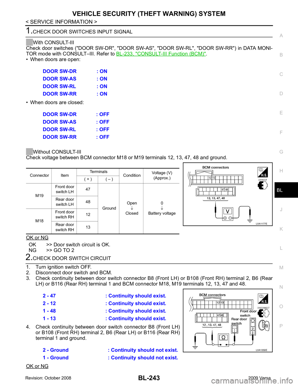
Check voltage between BCM connector M18 or M19 terminals 12, 13, 47, 48 and ground.
OK or NG OK >> Door switch circuit is OK.
NG >> GO TO 2 2.
CHECK DOOR SWITCH CIRCUIT
1. Turn ignition switch OFF.
2. Disconnect door switch and BCM.
3. Check continuity between door switch connector B8 (F ront LH) or B108 (Front RH) terminal 2, B6 (Rear
LH) or B116 (Rear RH) terminal 1 and BCM connector M18, M19 terminals 12, 13, 47 and 48.
4. Check continuity between door switch connector B8 (Front LH) or B108 (Front RH) terminal 2, B6 (Rear LH) or B116 (Rear RH)
terminal 1 and ground.
OK or NG DOOR SW-DR : ON
DOOR SW-AS : ON
DOOR SW-RL : ON
DOOR SW-RR : ON
DOOR SW-DR : OFF
DOOR SW-AS : OFF
DOOR SW-RL : OFF
DOOR SW-RR : OFF Connector Item
Terminals
ConditionVoltage (V)
(Approx.)
( + ) ( – )
M19 Front door
switch LH 47
Ground Open
↓
Closed 0
↓
Battery voltage
Rear door
switch LH 48
M18 Front door
switch RH 12
Rear door
switch RH 13 LIIA1177E
2 - 47 : Continuity should exist.
2 - 12 : Continuity should exist.
1 - 48 : Continuity should exist.
1 - 13 : Continuity should exist.
2 - Ground : Continuity should not exist.
1 - Ground : Continuity should not exist. LIIA1350E
Page 705 of 4331
BL-244< SERVICE INFORMATION >
VEHICLE SECURITY (T
HEFT WARNING) SYSTEM
OK >> GO TO 3
NG >> Repair or replace harness. 3.
CHECK DOOR SWITCHES
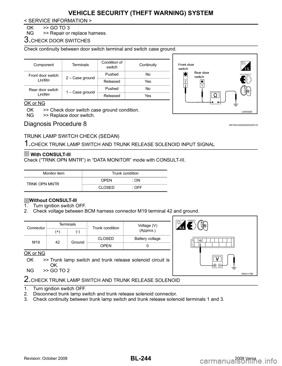
Check continuity between door switch terminal and switch case ground.
OK or NG OK >> Check door switch case ground condition.
NG >> Replace door switch.
Diagnosis Procedure 8 INFOID:0000000004305133
TRUNK LAMP SWITCH CHECK (SEDAN) 1.
CHECK TRUNK LAMP SWITCH AND TRUNK RELEASE SOLENOID INPUT SIGNAL
With CONSULT-III
Check (“TRNK OPN MNTR”) in “DATA MONITOR” mode with CONSULT-III.
Without CONSULT-III
1. Turn ignition switch OFF.
2. Check voltage between BCM harness connector M19 terminal 42 and ground.
OK or NG OK >> Trunk lamp switch and trunk release solenoid circuit is
OK.
NG >> GO TO 2 2.
CHECK TRUNK LAMP SWITCH A ND TRUNK RELEASE SOLENOID
1. Turn ignition switch OFF.
2. Disconnect trunk lamp switch and trunk release solenoid connector.
3. Check continuity between trunk lamp switch and trunk release solenoid terminals 1 and 3.
Component Terminals
Condition of
switch Continuity
Front door switch LH/RH 2 – Case ground Pushed No
Released Yes
Rear door switch LH/RH 1 – Case ground Pushed No
Released Yes LIIA0550E
Monitor item Trunk condition
TRNK OPN MNTR OPEN : ON
CLOSED : OFF Connector
Terminals
Trunk condition Voltage (V)
(Approx.)
(+) (-)
M19 42 Ground CLOSED Battery voltage
OPEN 0 WIIA1179E
Page 713 of 4331
BL-252< SERVICE INFORMATION >
NATS (NISSAN ANTI-THEFT SYSTEM)
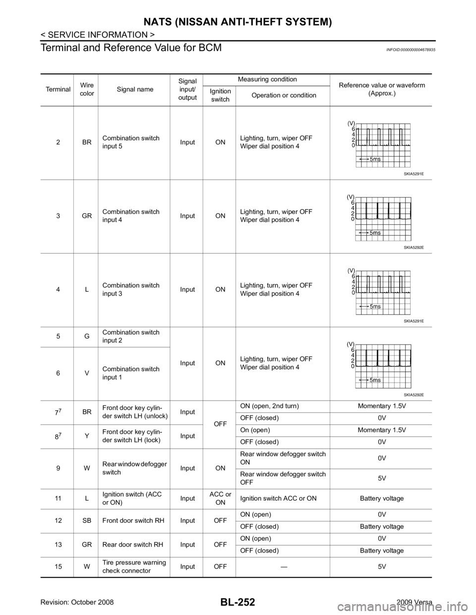
Terminal and Reference Value for BCM INFOID:0000000004678935
Terminal Wire
color Signal name Signal
input/
output Measuring condition
Reference value or waveform
(Approx.)
Ignition
switch Operation or condition
2 BR Combination switch
input 5 Input ONLighting, turn, wiper OFF
Wiper dial position 4
3 GR Combination switch
input 4 Input ONLighting, turn, wiper OFF
Wiper dial position 4
4 L Combination switch
input 3 Input ONLighting, turn, wiper OFF
Wiper dial position 4
5 G Combination switch
input 2
Input ONLighting, turn, wiper OFF
Wiper dial position 4
6 V Combination switch
input 1
7 7
BRFront door key cylin-
der switch LH (unlock) Input
OFFON (open, 2nd turn) Momentary 1.5V
OFF (closed) 0V
8 7
YFront door key cylin-
der switch LH (lock) InputOn (open) Momentary 1.5V
OFF (closed) 0V
9 W Rear window defogger
switch Input ONRear window defogger switch
ON 0V
Rear window defogger switch
OFF 5V
11 L Ignition switch (ACC
or ON) InputACC or
ON Ignition switch ACC or ON Battery voltage
12 SB Front door switch RH Input OFF ON (open) 0V
OFF (closed) Ba ttery voltage
13 GR Rear door switch RH Input OFF ON (open) 0V
OFF (closed) Ba ttery voltage
15 W Tire pressure warning
check connector Input OFF — 5V SKIA5291E
SKIA5292E
SKIA5291E
SKIA5292E
Page 714 of 4331
NATS (NISSAN ANTI-THEFT SYSTEM)
BL-253
< SERVICE INFORMATION >
C
D E
F
G H
J
K L
M A
B BL
N
O P
18 V
Remote keyless entry
receiver (ground) Output OFF — 0V
19 BR Remote keyless entry
receiver (power sup-
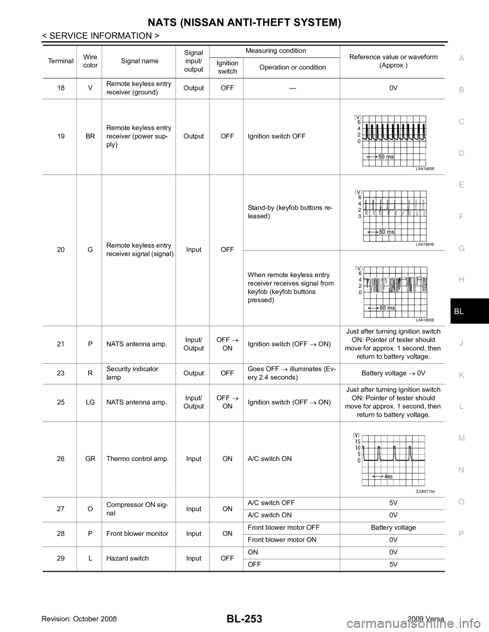
ply) Output OFF Ignition switch OFF
20 G Remote keyless entry
receiver signal (signal) Input OFFStand-by (keyfob buttons re-
leased)
When remote keyless entry
receiver receives signal from
keyfob (keyfob buttons
pressed)
21 P NATS antenna amp. Input/
Output OFF
→
ON Ignition switch (OFF
→ ON) Just after turning ignition switch
ON: Pointer of tester should
move for approx. 1 second, then return to battery voltage.
23 R Security indicator
lamp Output OFFGoes OFF
→ illuminates (Ev-
ery 2.4 seconds) Battery voltage
→ 0V
25 LG NATS antenna amp. Input/
Output OFF
→
ON Ignition switch (OFF
→ ON) Just after turning ignition switch
ON: Pointer of tester should
move for approx. 1 second, then
return to battery voltage.
26 GR Thermo control amp. Input ON A/C switch ON
27 O Compressor ON sig-
nal Input ONA/C switch OFF 5V
A/C switch ON 0V
28 P Front blower monitor Input ON Front blower motor OFF Battery voltage
Front blower motor ON 0V
29 L Hazard switch Input OFF ON 0V
OFF 5V
Terminal
Wire
color Signal name Signal
input/
output Measuring condition
Reference value or waveform
(Approx.)
Ignition
switch Operation or condition LIIA1893E
LIIA1894E
LIIA1895E
ZJIA0719J
Page 715 of 4331
BL-254< SERVICE INFORMATION >
NATS (NISSAN ANTI-THEFT SYSTEM)
30 1
VBack door/trunk out-
put Output —Back door open (switch
closed) 0V
Back door closed (switch
open) 5V
30 3
VBack door opener
switch Input —All doors locked (SW OFF) Battery voltage
All doors unlocked (SW ON) 0V
30 4
VTrunk lid opener
switch Input —All doors locked (SW OFF) Battery voltage
All doors unlocked (SW ON) 0V
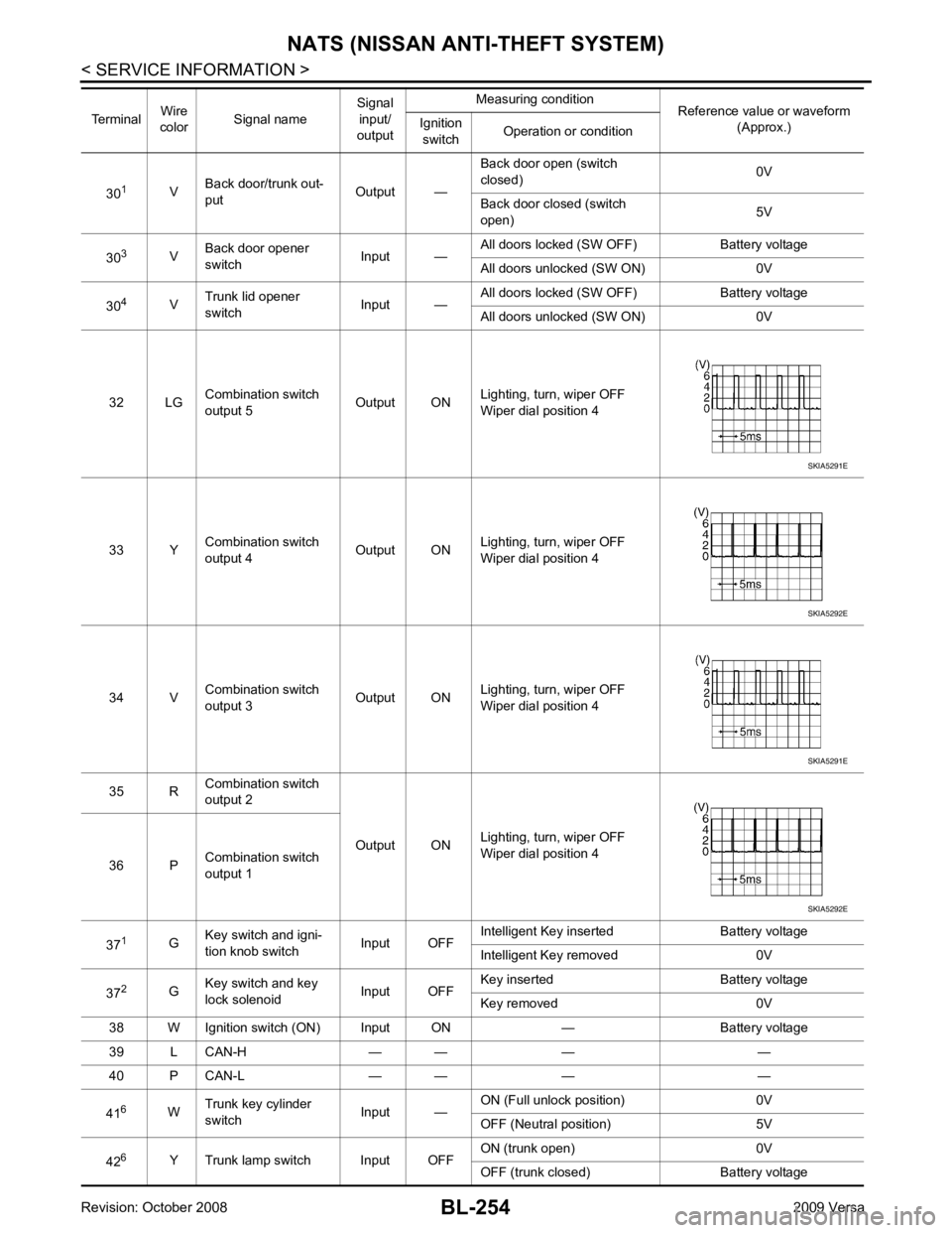
32 LG Combination switch
output 5 Output ONLighting, turn, wiper OFF
Wiper dial position 4
33 Y Combination switch
output 4 Output ON
Lighting, turn, wiper OFF
Wiper dial position 4
34 V Combination switch
output 3 Output ONLighting, turn, wiper OFF
Wiper dial position 4
35 R Combination switch
output 2
Output ONLighting, turn, wiper OFF
Wiper dial position 4
36 P Combination switch
output 1
37 1
GKey switch and igni-
tion knob switch Input OFFIntelligent Key inserted Battery voltage
Intelligent Key removed 0V
37 2
GKey switch and key
lock solenoid Input OFFKey inserted Battery voltage
Key removed 0V
38 W Ignition switch (ON) Input ON — Battery voltage
39 L CAN-H — — — —
40 P CAN-L — — — —
41 6
WTrunk key cylinder
switch Input —ON (Full unlock position) 0V
OFF (Neutral position) 5V
42 6
Y Trunk lamp switch Input OFF ON (trunk open) 0V
OFF (trunk closed) Battery voltage
Terminal
Wire
color Signal name Signal
input/
output Measuring condition
Reference value or waveform
(Approx.)
Ignition
switch Operation or condition SKIA5291E
SKIA5292E
SKIA5291E
SKIA5292E
Page 716 of 4331
NATS (NISSAN ANTI-THEFT SYSTEM)
BL-255
< SERVICE INFORMATION >
C
D E
F
G H
J
K L
M A
B BL
N
O P
43
5
R Back door switch Input OFF ON (open) 0V
OFF (closed) Battery voltage
44 5
LG Rear wiper auto stop Input ON Rear wiper operating 0
Rear wiper stopped Battery
45 7
GR Lock switch Input OFF ON (lock) 0V
OFF Battery voltage
46 7
L Unlock switch Input OFF ON (unlock) 0V
OFF Battery voltage
47 BR Front door switch LH Input OFF ON (open) 0V
OFF (closed) Battery voltage
48 O Rear door switch LH Input OFF ON (open) 0V
OFF (closed) Battery voltage
49 P Luggage room lamp Output OFF Any door open (ON) 0V
All doors closed (OFF) Battery voltage
50 SB A/C indicator Output ON A/C OFF 0
A/C ON Battery voltage
53 5
RBack door lock assem-
bly (actuator) Output OFF Back door (open) Battery voltage
53 6
RTrunk lamp switch and
trunk release solenoid Output OFF Trunk lid (open) Battery voltage
55 5
VRear wiper motor out-
put Output ONOFF 0
ON Battery voltage
56 R Battery saver output Output OFF
30 minutes after ignition
switch is turned OFF 0V
ON — Battery voltage
57 LG Battery power supply Input OFF — Battery voltage
59 7
GFront door lock actua-
tor LH (unlock) Output OFFOFF (neutral) 0V
ON (unlock) Battery voltage
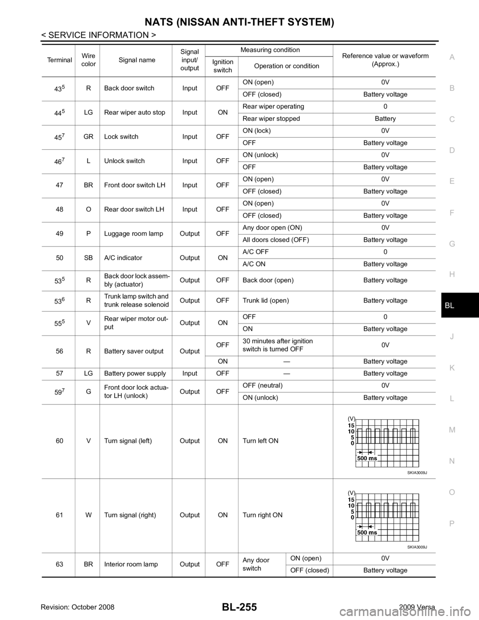
60 V Turn signal (left) Output ON Turn left ON
61 W Turn signal (right) Output ON Turn right ON
63 BR Interior room lamp Output OFF Any door
switch ON (open) 0V
OFF (closed) Battery voltage
Terminal
Wire
color Signal name Signal
input/
output Measuring condition
Reference value or waveform
(Approx.)
Ignition
switch Operation or condition SKIA3009J
SKIA3009J
Page 736 of 4331
BL
N
O P
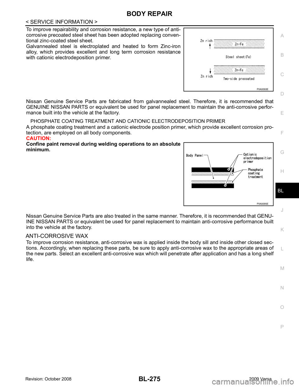
To improve repairability and corrosion resistance, a new type of anti-
corrosive precoated steel sheet has been adopted replacing conven-
tional zinc-coated steel sheet.
Galvannealed steel is electroplated and heated to form Zinc-iron
alloy, which provides excellent and long term corrosion resistance
with cationic electrodeposition primer.
Nissan Genuine Service Parts are fabricated from galvannealed steel. Therefore, it is recommended that
GENUINE NISSAN PARTS or equivalent be used for panel replacement to maintain the anti-corrosive perfor-
mance built into the vehicle at the factory.
PHOSPHATE COATING TREATMENT AND CA TIONIC ELECTRODEPOSITION PRIMER
A phosphate coating treatment and a cationic electrode posit ion primer, which provide excellent corrosion pro-
tection, are employed on all body components.
CAUTION:
Confine paint removal during weld ing operations to an absolute
minimum.
Nissan Genuine Service Parts are also treated in the same manner. Therefore, it is recommended that GENU-
INE NISSAN PARTS or equivalent be used for panel repl acement to maintain anti-corrosive performance built
into the vehicle at the factory.
ANTI-CORROSIVE WAX To improve corrosion resistance, anti-corrosive wax is applied inside the body sill and inside other closed sec-
tions. Accordingly, when replacing these parts, be sure to apply anti-corrosive wax to the appropriate areas of
the new parts. Select an excellent anti-corrosive wax which will penetrate after application and has a long shelf
life. PIIA0095E
Page 772 of 4331
BL
N
O P
- Remove foam material remaining on vehicle side.
- Clean area in which foam was removed.
- Install service part.
- Insert nozzle into hole near fill area and fill foam material or fill in enough to close gap with the service
part.
2. Fill procedures before installation of service part.
- Remove foam material remaining on vehicle side.
- Clean area in which foam was removed.
- Fill foam material on wheelhouse outer side. NOTE:
Fill in enough to close gap with service part while avoiding flange area.
- Install service part.
NOTE:
Refer to label for information on working times.
Hatchback LIIA1082E