2009 NISSAN LATIO suspension
[x] Cancel search: suspensionPage 3245 of 4331
FRONT SUSPENSION ASSEMBLY
FSU-11
< SERVICE INFORMATION >
C
D
F
G H
I
J
K L
M A
B FSU
N
O P
Removal and Installation
INFOID:0000000004305866
REMOVAL 1. Separate intermediate shaft from steering gear pinion shaft. Refer to PS-9, " Removal and Installation " .
2. Remove front tires from vehicle using a power tool.
3. Remove wheel sensor from steering knuckle. Refer to BRC-32 .
CAUTION:
Do not pull on wheel sensor harness.
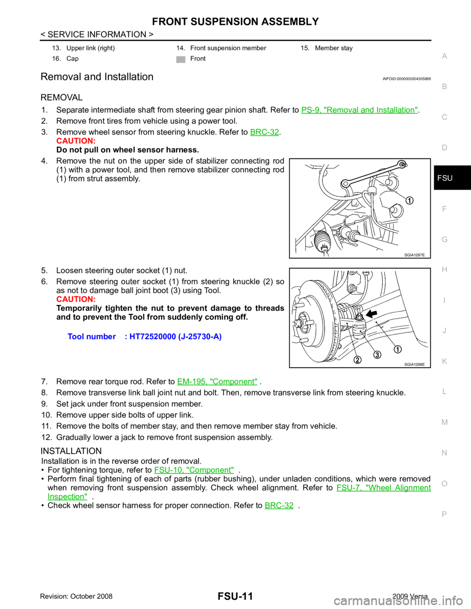
4. Remove the nut on the upper side of stabilizer connecting rod (1) with a power tool, and then remove stabilizer connecting rod
(1) from strut assembly.
5. Loosen steering outer socket (1) nut.
6. Remove steering outer socket (1) from steering knuckle (2) so as not to damage ball joint boot (3) using Tool.
CAUTION:
Temporarily tighten the nut to prevent damage to threads
and to prevent the Tool fr om suddenly coming off.
7. Remove rear torque rod. Refer to EM-195, " Component " .
8. Remove transverse link ball joint nut and bolt. Then, remove transverse link from steering knuckle.
9. Set jack under front suspension member.
10. Remove upper side bolts of upper link.
11. Remove the bolts of member stay, and then remove member stay from vehicle.
12. Gradually lower a jack to remove front suspension assembly.
INSTALLATION Installation is in the reverse order of removal.
• For tightening torque, refer to FSU-10, " Component " .
• Perform final tightening of each of parts (rubber bushing), under unladen conditions, which were removed when removing front suspension assembly. Check wheel alignment. Refer to FSU-7, " Wheel Alignment
Inspection " .
• Check wheel sensor harness for proper connection. Refer to BRC-32 .
13. Upper link (right) 14. Front suspension member 15. Member stay
16. Cap Front SGIA1297E
Tool number : HT72520000 (J-25730-A)
SGIA1298E
Page 3249 of 4331
FSU
N
O P
TRANSVERSE LINK
Removal and Installation INFOID:0000000004305869
REMOVAL 1. Remove front tires using power tool.
2. Remove transverse link ball joint nut and bolt. Then, remove transverse link from steering knuckle.
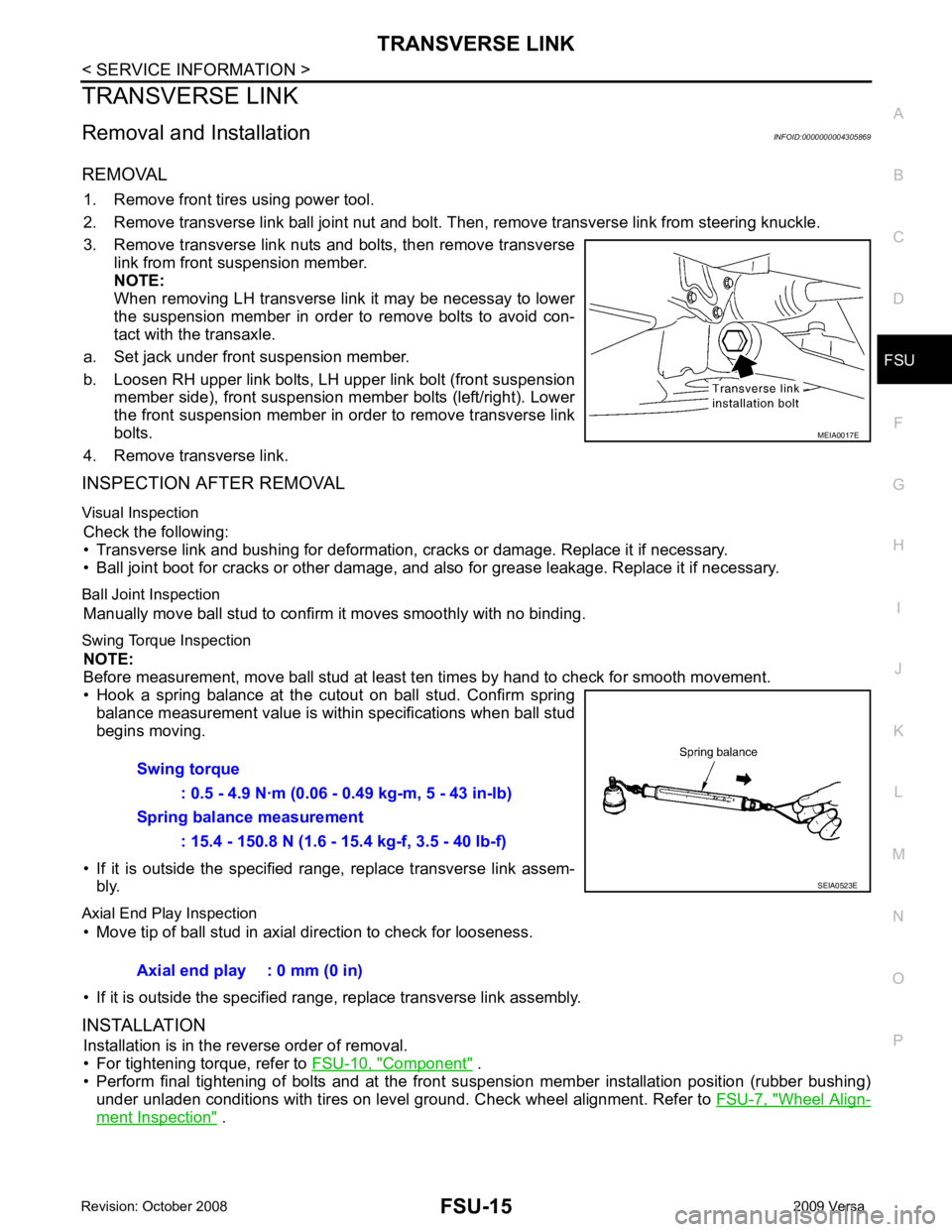
3. Remove transverse link nuts and bolts, then remove transverse link from front suspension member.
NOTE:
When removing LH transverse link it may be necessay to lower
the suspension member in order to remove bolts to avoid con-
tact with the transaxle.
a. Set jack under front suspension member.
b. Loosen RH upper link bolts, LH upper link bolt (front suspension member side), front suspension member bolts (left/right). Lower
the front suspension member in order to remove transverse link
bolts.
4. Remove transverse link.
INSPECTION AFTER REMOVAL
Visual Inspection Check the following:
• Transverse link and bushing for deformation, cracks or damage. Replace it if necessary.
• Ball joint boot for cracks or other damage, and also for grease leakage. Replace it if necessary.
Ball Joint Inspection Manually move ball stud to confirm it moves smoothly with no binding.
Swing Torque Inspection NOTE:
Before measurement, move ball stud at least t en times by hand to check for smooth movement.
• Hook a spring balance at the cutout on ball stud. Confirm spring balance measurement value is within specifications when ball stud
begins moving.
• If it is outside the specified range, replace transverse link assem- bly.
Axial End Play Inspection • Move tip of ball stud in axial direction to check for looseness.
• If it is outside the specified range, replace transverse link assembly.
INSTALLATION Installation is in the reverse order of removal.
• For tightening torque, refer to FSU-10, " Component " .
• Perform final tightening of bolts and at the front suspension member installation position (rubber bushing)
under unladen conditions with tires on level ground. Check wheel alignment. Refer to FSU-7, " Wheel Align-
ment Inspection " .
Page 3250 of 4331
FSU-16< SERVICE INFORMATION >
STABILIZER BAR
STABILIZER BAR
Removal and Installation INFOID:0000000004305870
REMOVAL
1. Separate intermediate shaft from steering gear pinion shaft. Refer to PS-9, " Removal and Installation " .
2. Remove front tires using power tool.
3. Remove the nut on the lower side of stabilizer connec ting rod using power tool, and then remove stabilizer
connecting rod from stabilizer bar.
4. If necessary remove stabilize connecting rod upper nut using power tool. Separate stabilizer connecting rod and strut.
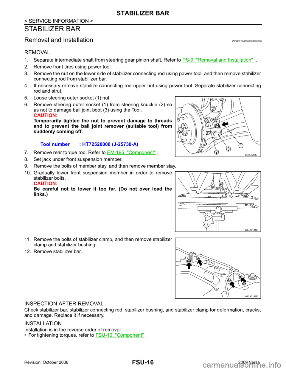
5. Loose steering outer socket (1) nut.
6. Remove steering outer socket (1) from steering knuckle (2) so as not to damage ball joint boot (3) using the Tool.
CAUTION:
Temporarily tighten the nut to prevent damage to threads
and to prevent the ball joint remover (suitable tool) from
suddenly coming off.
7. Remove rear torque rod. Refer to EM-195, " Component " .
8. Set jack under front suspension member.
9. Remove the bolts of member stay, and then remove member stay.
10. Gradually lower front suspension member in order to remove stabilizer bolts.
CAUTION:
Be careful not to lower it too far. (Do not over load the
links.)
11. Remove the bolts of stabilizer clamp, and then remove stabilizer clamp and stabilizer bushing.
12. Remove stabilizer bar.
INSPECTION AFTER REMOVAL
Check stabilizer bar, stabilizer connecting rod, stabilizer bushing, and stabilizer clamp for deformation, cracks,
and damage. Replace it if necessary.
INSTALLATION
Installation is in the reverse order of removal.
• For tightening torques, refer to FSU-10, " Component " .
Tool number : HT72520000 (J-25730-A) SGIA1298E
WEIA0181E
WEIA0182E
Page 3754 of 4331
MA
N
O P
Abbreviations: R = Replace. I = Inspect. Corr
ect or replace if necessary. L = Lubricate.
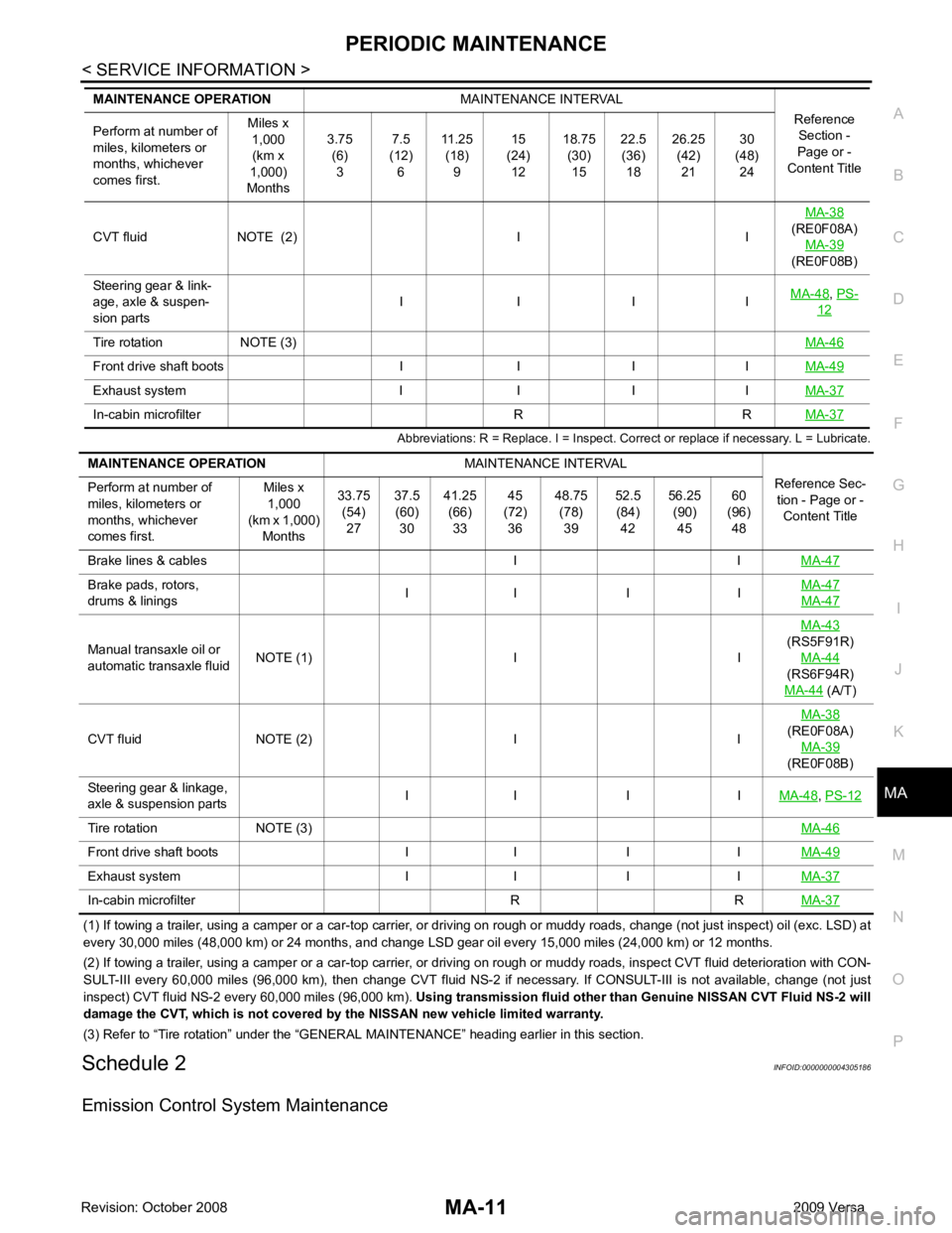
(1) If towing a trailer, using a camper or a car-top carrier, or driving on rough or muddy roads, change (not just inspect) oil (exc. LSD) at
every 30,000 miles (48,000 km) or 24 months, and change LSD gear oil every 15,000 miles (24,000 km) or 12 months.
(2) If towing a trailer, using a camper or a car-top carrier, or driving on rough or muddy roads, inspect CVT fluid deteriorati on with CON-
SULT-III every 60,000 miles (96,000 km), then change CVT fluid NS-2 if necessary. If CONSULT-III is not available, change (not just
inspect) CVT fluid NS-2 every 60,000 miles (96,000 km). Using transmission fluid other than Genuine NISSAN CVT Fluid NS-2 will
damage the CVT, which is not covered by the NISSAN new vehicle limited warranty.
(3) Refer to “Tire rotation” under the “GENERAL MAINTENANCE” heading earlier in this section.
Schedule 2 INFOID:0000000004305186
Emission Control System Maintenance CVT fluid NOTE (2) I I
MA-38
(RE0F08A) MA-39
(RE0F08B)
Steering gear & link-
age, axle & suspen-
sion parts I I I I
MA-48 ,
PS- 12
Tire rotation NOTE (3)
MA-46Front drive shaft boots I I I I
MA-49Exhaust system I I I I
MA-37In-cabin microfilter R R
MA-37Brake pads, rotors,
drums & linings I I I I MA-47 MA-47
Manual transaxle oil or
automatic transaxle fluid NOTE (1) I I MA-43
(RS5F91R) MA-44
(RS6F94R)
MA-44 (A/T)
CVT fluid NOTE (2) I I MA-38
(RE0F08A)
MA-39
(RE0F08B)
Steering gear & linkage,
axle & suspension parts I I I I
MA-48 ,
PS-12 Tire rotation NOTE (3)
MA-46Front drive shaft boots I I I I
MA-49Exhaust system I I I I
MA-37In-cabin microfilter R R
MA-37
Page 3756 of 4331
MA
N
O P
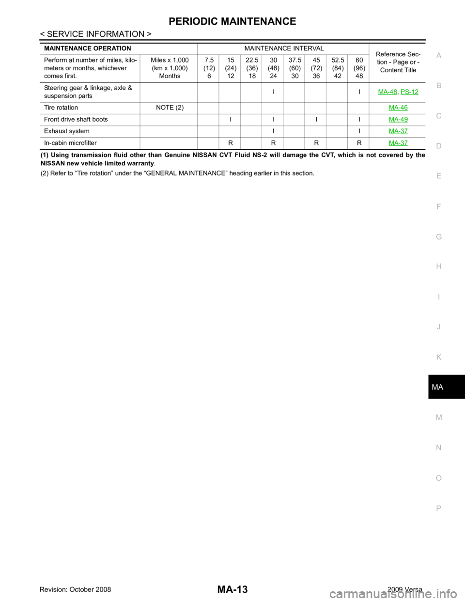
(1) Using transmission fluid other than Genuine NISSAN CVT Flui
d NS-2 will damage the CVT, which is not covered by the
NISSAN new vehicle limited warranty .
(2) Refer to “Tire rotation” under the “GENERAL MAINTENANCE” heading earlier in this section.
Steering gear & linkage, axle &
suspension parts I I
MA-48 ,
PS-12 Tire rotation NOTE (2)
MA-46Front drive shaft boots I I I I
MA-49Exhaust system I I
MA-37In-cabin microfilter R R R R
MA-37
Page 3791 of 4331
MA-48< SERVICE INFORMATION >
CHASSIS AND BODY MAINTENANCE
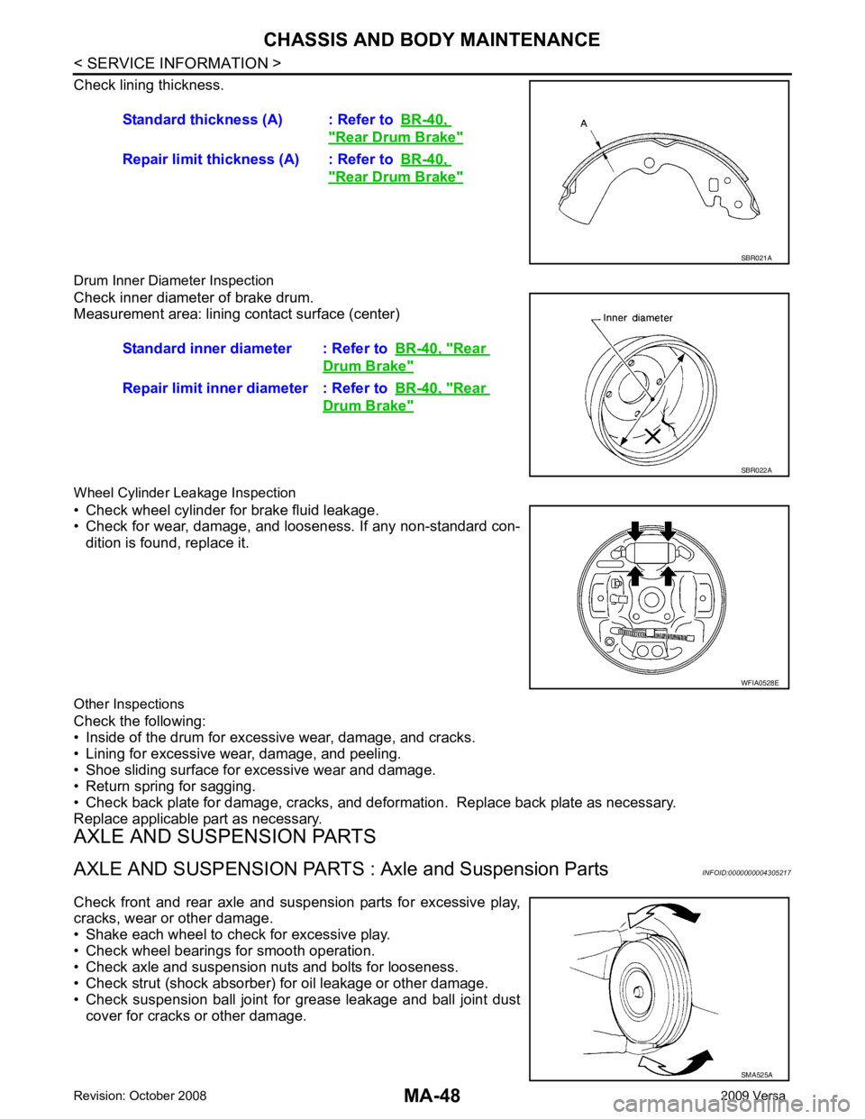
Check lining thickness.
Drum Inner Diameter Inspection
Check inner diameter of brake drum.
Measurement area: lining contact surface (center)
Wheel Cylinder Leakage Inspection
• Check wheel cylinder for brake fluid leakage.
• Check for wear, damage, and looseness. If any non-standard con-
dition is found, replace it.
Other Inspections
Check the following:
• Inside of the drum for excessive wear, damage, and cracks.
• Lining for excessive wear, damage, and peeling.
• Shoe sliding surface for excessive wear and damage.
• Return spring for sagging.
• Check back plate for damage, cracks, and deforma tion. Replace back plate as necessary.
Replace applicable part as necessary.
AXLE AND SUSPENSION PARTS
AXLE AND SUSPENSION PARTS : Axle and Suspension Parts INFOID:0000000004305217
Check front and rear axle and suspension parts for excessive play,
cracks, wear or other damage.
• Shake each wheel to check for excessive play.
• Check wheel bearings for smooth operation.
• Check axle and suspension nuts and bolts for looseness.
• Check strut (shock absorber) for oil leakage or other damage.
• Check suspension ball joint for grease leakage and ball joint dust cover for cracks or other damage. Standard thickness (A) : Refer to
BR-40, " Rear Drum Brake "
Repair limit thickness (A) : Refer to
BR-40, " Rear Drum Brake "
SBR021A
Standard inner diameter : Refer to
BR-40, " Rear
Drum Brake "
Repair limit inner diameter : Refer to
BR-40, " Rear
Drum Brake "
SBR022A
WFIA0528E
SMA525A
Page 4061 of 4331
PS
N
O P
NOISE, VIBRATION AND HARSHN
ESS (NVH) TROUBLESHOOTING
NVH Troubleshooting Chart INFOID:0000000004305930
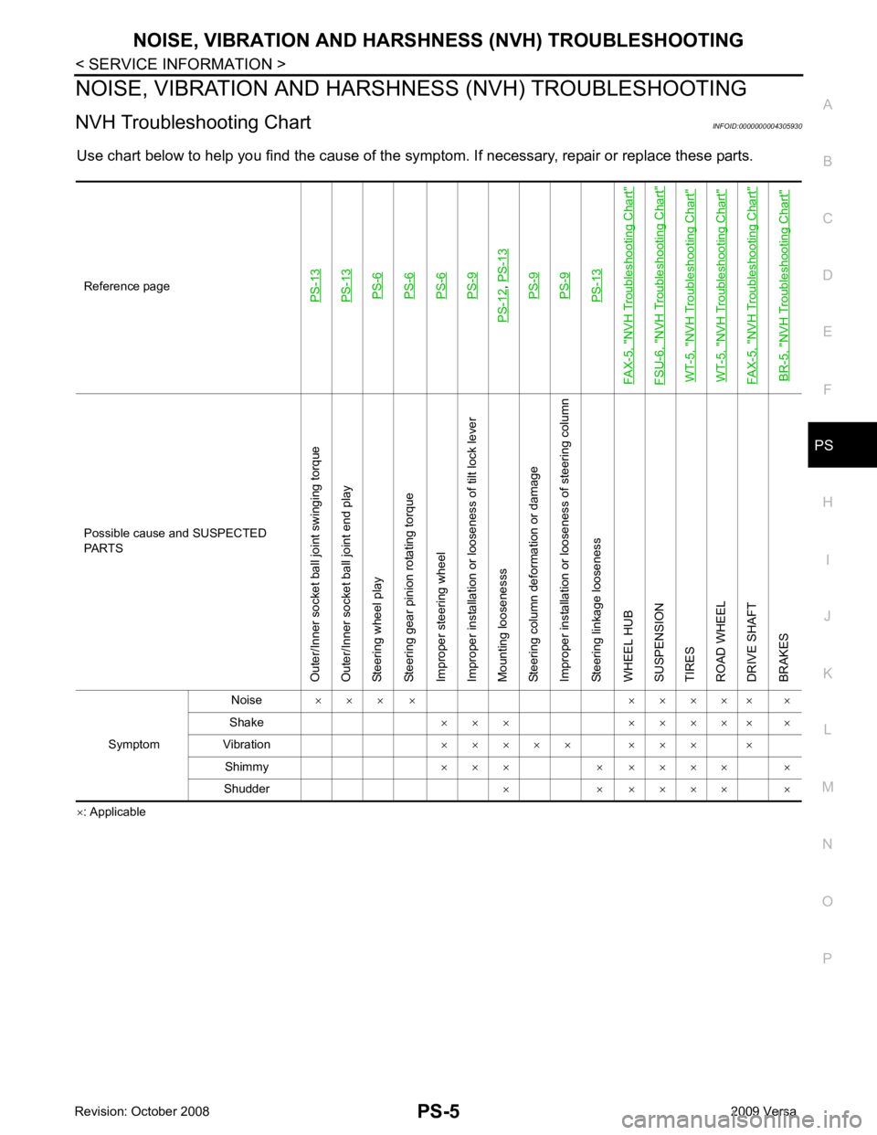
Use chart below to help you find the cause of the symptom. If necessary, repair or replace these parts.
× : ApplicableReference pagePS-13PS-13PS-6PS-6PS-6PS-9
PS-12
,
PS-13PS-9PS-9PS-13
FAX-5, "
NVH Troubleshooting Chart
"
FSU-6, "
NVH Troubleshooting Chart
"
WT-5, "
NVH Troubleshooting Chart
"
WT-5, "
NVH Troubleshooting Chart
"
FAX-5, "
NVH Troubleshooting Chart
"
BR-5, "
NVH Troubleshooting Chart
" Possible cause and SUSPECTED
PARTS
Outer/Inner socket ball joint swinging torque
Outer/Inner socket ball joint end play
Steering wheel play
Steering gear pinion rotating torque
Improper steering wheel
Improper installation or looseness of tilt lock lever
Mounting loosenesss
Steering column deformation or damage
Improper installation or looseness of steering column
Steering linkage looseness
WHEEL HUB
SUSPENSION
TIRES
ROAD WHEEL
DRIVE SHAFT
BRAKES
Symptom Noise
× × × × × × × × × ×
Shake × × × × × × × × ×
Vibration × × × × × × × × ×
Shimmy × × × × × × × × ×
Shudder × × × × × × ×
Page 4063 of 4331
PS
N
O P
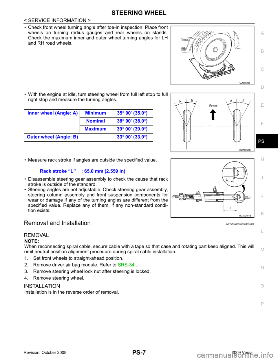
• Check front wheel turning angle after toe-in inspection. Place front
wheels on turning radius gauges and rear wheels on stands.
Check the maximum inner and outer wheel turning angles for LH
and RH road wheels.
• With the engine at idle, turn steering wheel from full left stop to full right stop and measure the turning angles.
• Measure rack stroke if angles are outside the specified value.
• Disassemble steering gear assembly to check the cause that rack stroke is outside of the standard.
• Steering angles are not adjustabl e. Check steering gear assembly,
steering column assembly and front suspension components for
wear or damage if any of the turning angles are different from the
specified value. Replace any of them, if any non-standard condi-
tion exists.
Removal and Installation INFOID:0000000004305932
REMOVAL NOTE:
When reconnecting spiral cable, secure cable with a tape so that case and rotating part keep aligned. This will
omit neutral position alignment procedure during spiral cable installation.
1. Set front wheels to straight-ahead position.
2. Remove driver air bag module. Refer to SRS-34 .
3. Remove steering wheel lock nut after steering is locked.
4. Remove steering wheel.
INSTALLATION Installation is in the reverse order of removal.