2009 NISSAN LATIO seat adjustment
[x] Cancel search: seat adjustmentPage 3607 of 4331
LT
N
O P
CONTENTS
LIGHTING SYSTEM
SERVICE INFORMATION .. ..........................3
PRECAUTIONS .............................................. .....3
Precaution for Supplemental Restraint System
(SRS) "AIR BAG" and "SEAT BELT PRE-TEN-
SIONER" ............................................................. ......
3
Precaution Necessary fo r Steering Wheel Rota-
tion After Battery Disconnect ............................... ......
3
HEADLAMP (FOR USA) ................................ .....4
Component Parts and Harness Connector Loca-
tion ...................................................................... ......
4
System Description ............................................. ......4
CAN COMMUNICATION SYSTEM DESCRIP-
TION .................................................................... ......
5
Schematic ........................................................... ......6
Wiring Diagram ................................................... ......7
Terminal and Reference Value for BCM ............. ....10
Terminal and Reference Value for IPDM E/R ..... ....10
How to Perform Trouble Diagnosis ..................... ....11
Preliminary Check ............................................... ....11
CONSULT-III Function (BCM) ............................. ....11
CONSULT-III Function (IPDM E/R) ..................... ....12
Headlamp High Beam Does Not Illuminate (Both
Sides) .................................................................. ....
13
Headlamp High Beam Does Not Illuminate (One
Side) .................................................................... ....
15
High Beam Indicator Lamp Does Not Illuminate .....16
Headlamp Low Beam Does Not Illuminate (Both
Sides) .................................................................. ....
16
Headlamp Low Beam Does Not Illuminate (One
Side) .................................................................... ....
19
Headlamps Do Not Turn OFF ............................. ....20
Aiming Adjustment .............................................. ....21
Bulb Replacement ........ ...........................................22
Removal and Installation .........................................23
Disassembly and Assembly ................................ ....23
HEADLAMP (FOR CANADA) - DAYTIME
LIGHT SYSTEM - ........................................... ....25 Component Parts and Harness Connector Loca-
tion ....................................................................... ....
25
Page 3744 of 4331
MA
N
O P
CONTENTS
MAINTENANCE
SERVICE INFORMATION .. ..........................3
PRECAUTIONS .............................................. .....3
Precaution for Supplemental Restraint System
(SRS) "AIR BAG" and "SEAT BELT PRE-TEN-
SIONER" ............................................................. ......
3
Precaution Necessary fo r Steering Wheel Rota-
tion After Battery Disconnect ............................... ......
3
PREPARATION .............................................. .....5
Special Service Tool ........................................... ......5
Commercial Service Tool .................................... ......5
GENERAL MAINTE NANCE ........................... .....6
Explanation of General Maintenance .................. ......6
General Maintenance .......................................... ......6
PERIODIC MAINTENANCE ........................... .....9
Introduction of Periodic Maintenance .................. ......9
Schedule 1 .......................................................... ......9
Schedule 2 .......................................................... ....11
RECOMMENDED FLUIDS AND LUBRI-
CANTS ............................................................ ....
14
Fluids and Lubricants .......................................... ....14
SAE Viscosity Number ........................................ ....14
Anti-freeze Coolant Mixture Ratio ....................... ....15
ENGINE MAINTENANCE (HR16DE) ............. ....16
DRIVE BELT .......................................................... ....16
DRIVE BELT : Checking ..................................... ....16
DRIVE BELT : Tension Adjustment .................... ....16
ENGINE COOLANT ............................................... ....17
ENGINE COOLANT : Inspection ......................... ....17
ENGINE COOLANT : Changing Engine Coolant .... 17
FUEL LINES .......................................................... ....19
FUEL LINES : Checking Fuel Line ...................... ....19
AIR CLEANER FILTER ......................................... ....19 AIR CLEANER FILTER : Re
moval and Installation
....20
ENGINE OIL ........................................................... ....20
ENGINE OIL : Inspection ..................................... ....20
ENGINE OIL : Draining ........................................ ....22
ENGINE OIL : Refilling ........................................ ....22
OIL FILTER ............................................................ ....22
OIL FILTER : Removal and Installation ...................23
SPARK PLUG (HR16DE) ...................................... ....23
SPARK PLUG (HR16DE) : Exploded View ......... ....24
SPARK PLUG (HR16DE) : Removal and Installa-
tion ....................................................................... ....
24
EVAP VAPOR LINES ............................................ ....25
EVAP VAPOR LINES : Checking EVAP Vapor
Line ...................................................................... ....
25
ENGINE MAINTENANCE (MR18DE) ............... 26
DRIVE BELT .......................................................... ....26
DRIVE BELT : Component .................................. ....26
DRIVE BELT : Checking Drive Belts ................... ....26
DRIVE BELT : Tension Adjustment ..................... ....26
ENGINE COOLANT ............................................... ....26
ENGINE COOLANT : Inspection ......................... ....26
ENGINE COOLANT : Changing Engine Coolant .... 27
FUEL LINES ........................................................... ....29
FUEL LINES : Checking Fuel Line ...................... ....29
AIR CLEANER FILTER ......................................... ....29
AIR CLEANER FILTER : Component .................. ....29
AIR CLEANER FILTER : Changing Air Cleaner
Filter ..................................................................... ....
30
ENGINE OIL ........................................................... ....30
ENGINE OIL : Inspection ..................................... ....30
ENGINE OIL : Changing Engine Oil .................... ....32
OIL FILTER ............................................................ ....33
Page 3750 of 4331
MA
N
O P
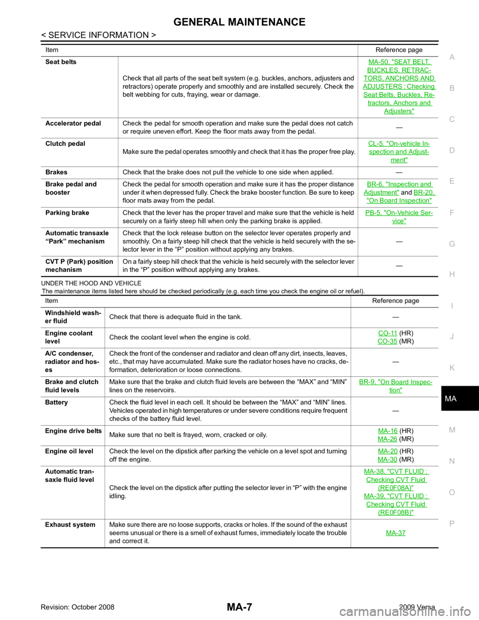
UNDER THE HOOD AND VEHICLE
The maintenance items listed here should be checked periodically (e.g. each time you check the engine oil or refuel).
Seat belts
Check that all parts of the seat belt system (e.g. buckles, anchors, adjusters and
retractors) operate properly and smoothly and are installed securely. Check the
belt webbing for cuts, fraying, wear or damage. MA-50, " SEAT BELT,
BUCKLES, RETRAC-
TORS, ANCHORS AND
ADJUSTERS : Checking
Seat Belts, Buckles, Re-
tractors, Anchors and
Adjusters "
On-vehicle In-
spection and Adjust-
ment "
Inspection and
Adjustment " and
BR-20, " On Board Inspection "
On-Vehicle Ser-
vice "
Item
Reference page
Windshield wash-
er fluid Check that there is adequate fluid in the tank. —
Engine coolant
level Check the coolant level when the engine is cold. CO-11 (HR)
CO-35 (MR)
A/C condenser,
radiator and hos-
es Check the front of the condenser and radiator and clean off any dirt, insects, leaves,
etc., that may have accumulated. Make sure the radiator hoses have no cracks, de-
formation, deterioration or loose connections. —
Brake and clutch
fluid levels Make sure that the brake and clutch fluid levels are between the “MAX” and “MIN”
lines on the reservoirs. BR-9, " On Board Inspec-
tion "
(HR)
MA-26 (MR)
Engine oil level Check the level on the dipstick after parking the vehicle on a level spot and turning
off the engine. MA-20 (HR)
MA-30 (MR)
Automatic tran-
saxle fluid level Check the level on the dipstick after putting the selector lever in “P” with the engine
idling. MA-38, " CVT FLUID :
Checking CVT Fluid
(RE0F08A) "
MA-39, " CVT FLUID :
Checking CVT Fluid
(RE0F08B) "
Page 3759 of 4331
MA-16< SERVICE INFORMATION >
ENGINE MAINTENANCE (HR16DE)
ENGINE MAINTENANCE (HR16DE)
DRIVE BELT
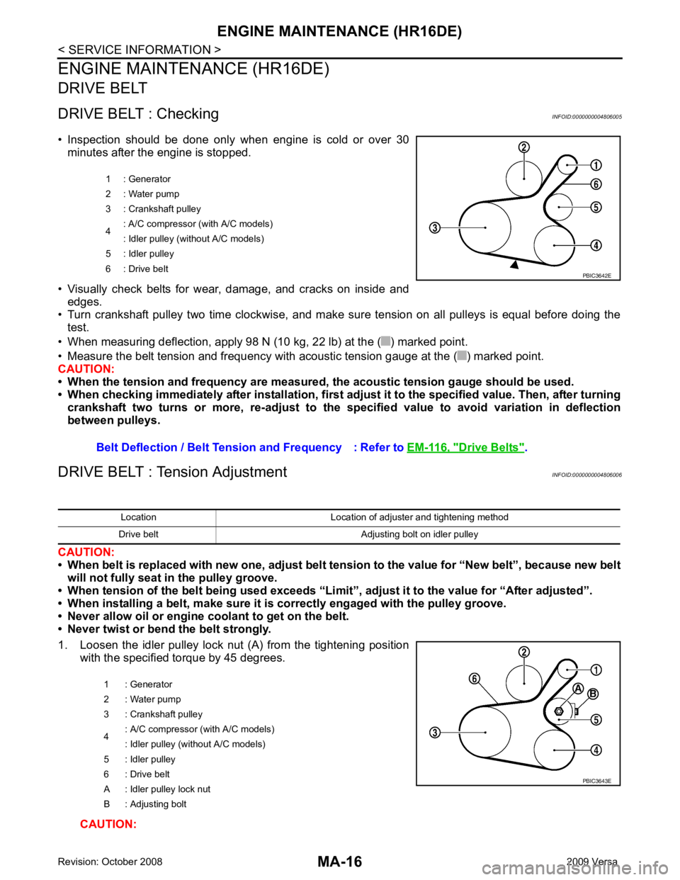
DRIVE BELT : Checking INFOID:0000000004806005
• Inspection should be done only when engine is cold or over 30 minutes after the engine is stopped.
• Visually check belts for wear, damage, and cracks on inside and edges.
• Turn crankshaft pulley two time clockwise, and make sure tension on all pulleys is equal before doing the test.
• When measuring deflection, apply 98 N (10 kg, 22 lb) at the ( ) marked point.
• Measure the belt tension and frequency with acous tic tension gauge at the ( ) marked point.
CAUTION:
• When the tension and frequency are measured, the acoustic tension gauge should be used.
• When checking immediately after installation, first ad just it to the specified value. Then, after turning
crankshaft two turns or more, re-adjust to the sp ecified value to avoid variation in deflection
between pulleys.
DRIVE BELT : Tension Adjustment INFOID:0000000004806006
CAUTION:
• When belt is replaced with new one, adjust belt tension to the value for “New belt”, because new belt
will not fully seat in the pulley groove.
• When tension of the belt being used exceeds “Limit”, adjust it to the value for “After adjusted”.
• When installing a belt, make sure it is correctly engaged with the pulley groove.
• Never allow oil or engine coolant to get on the belt.
• Never twist or bend the belt strongly.
1. Loosen the idler pulley lock nut (A) from the tightening position with the specified torque by 45 degrees.
CAUTION: 1 : Generator
2 : Water pump
3 : Crankshaft pulley
4 : A/C compressor (with A/C models)
: Idler pulley (without A/C models)
5 : Idler pulley
6 : Drive belt
Belt Deflection / Belt Tension and Frequency : Refer to EM-116, " Drive Belts " . PBIC3642E
Location Location of adjuster and tightening method
Drive belt Adjusting bolt on idler pulley
1 : Generator
2 : Water pump
3 : Crankshaft pulley
4 : A/C compressor
(with A/C models)
: Idler pulley (without A/C models)
5 : Idler pulley
6 : Drive belt
A : Idler pulley lock nut
B : Adjusting bolt PBIC3643E
Page 3886 of 4331
MTC
N
O P
CONTENTS
MANUAL AIR CONDITIONER
SERVICE INFORMATION .. ..........................3
PRECAUTIONS .............................................. .....3
Precaution for Supplemental Restraint System
(SRS) "AIR BAG" and "SEAT BELT PRE-TEN-
SIONER" ............................................................. ......
3
Precaution Necessary fo r Steering Wheel Rota-
tion After Battery Disconnect ............................... ......
3
Precaution for Procedure without Cowl Top Cover ......4
Precaution for Working with HFC-134a (R-134a) ......4
General Refrigerant Precaution .......................... ......4
Oil Precaution ...................................................... ......5
Precaution for Refrigeran t Connection ......................5
Precaution for Service of Compressor ................ ......7
Precaution for Service Equipment ....................... ......8
Precaution for Leak Detection Dye ..................... ......9
PREPARATION .............................................. ....11
HFC-134a (R-134a) Service Tool and Equipment ....11
Commercial Service Tool .................................... ....13
REFRIGERATION SYSTEM .......................... ....15
Refrigerant Cycle ................................................ ....15
Refrigerant System Protec tion ................................15
Component Part Location ................................... ....16
OIL .................................................................. ....17
Maintenance of Oil Quantity in Compressor ....... ....17
AIR CONDITIONER CONTROL ..................... ....19
Control Operation ................................................ ....19
Discharge Air Flow .............................................. ....20
System Description ............................................. ....20
TROUBLE DIAGNOSIS ................................. ....22
CONSULT-II Function (BCM) .............................. ....22
How to Perform Trouble Diagnosis for Quick and
Accurate Repair ........... ...........................................
22
Component Parts and Harness Connector Loca-
tion ...................................................................... ....
23
Schematic ........................................................... ....25
Wiring Diagram - Heater - ................................... ....26 Wiring Diagram - A/C,M - ....................................
....27
Operational Check ............................................... ....30
Mode Door ........................................................... ....31
Air Mix Door ......................................................... ....32
Intake Door .......................................................... ....33
Front Blower Motor Circuit .......................................33
Magnet Clutch Circuit (If Equipped) ..................... ....37
Insufficient Cooling .............................................. ....45
Insufficient Heating .............................................. ....52
Noise ................................................................... ....53
CONTROLLER .................................................. 55
Removal and Installation ..................................... ....55
Disassembly and Assembly ................................. ....56
THERMO CONTROL AMPLIFIER .................... 57
Removal and Installation ..................................... ....57
A/C UNIT ASSEMBLY ...................................... 58
Removal and Installation ..................................... ....58
Disassembly and Assembly ................................. ....60
BLOWER MOTOR ............................................ 62
Removal and Installation ..................................... ....62
INTAKE DOOR .................................................. 63
Intake Door Cable Adjustment ............................. ....63
AIR MIX DOOR ................................................. 64
Air Mix Door Cable Adjustment ........................... ....64
MODE DOOR .................................................... 65
Mode Door Cable Adjustment ............................. ....65
BLOWER FAN RESISTOR ............................... 66
Removal and Installation ..................................... ....66
HEATER CORE ................................................. 67
Removal and Installation ..................................... ....67
AIR CONDITIONER FILTER ............................. 68
Removal and Installation ..................................... ....68
Page 4062 of 4331
Removal and Instal-
lation " .
CHECKING STEERING WHEEL PLAY
• Turn steering wheel so that front wheels come to the straight-ahead position. Start engine and lightly turn
steering wheel to the left and right until front wheels start to move. Measure steering wheel movement on the
outer circumference.
• When the measurement value is outside the standard val ue, check backlash for each joint of steering col-
umn assembly and installation condition of steering gear assembly.
CHECKING NEUTRAL POSITION STEERING WHEEL
• Make sure that steering gear assembly, steering colu mn assembly and steering wheel are installed in the
correct position.
• Perform neutral position inspection after wheel alignment. Refer to PS-2, " Precaution for Supplemental
Restraint System (SRS) "AIR BA
G" and "SEAT BELT PRE-TENSIONER" " .
• Set vehicle to the straight-ahead position and c onfirm steering wheel is in the neutral position.
• Loosen outer socket lock nut and turn inner socket to left and right equally to make fine adjustments if steer-
ing wheel is not in the neutral position.
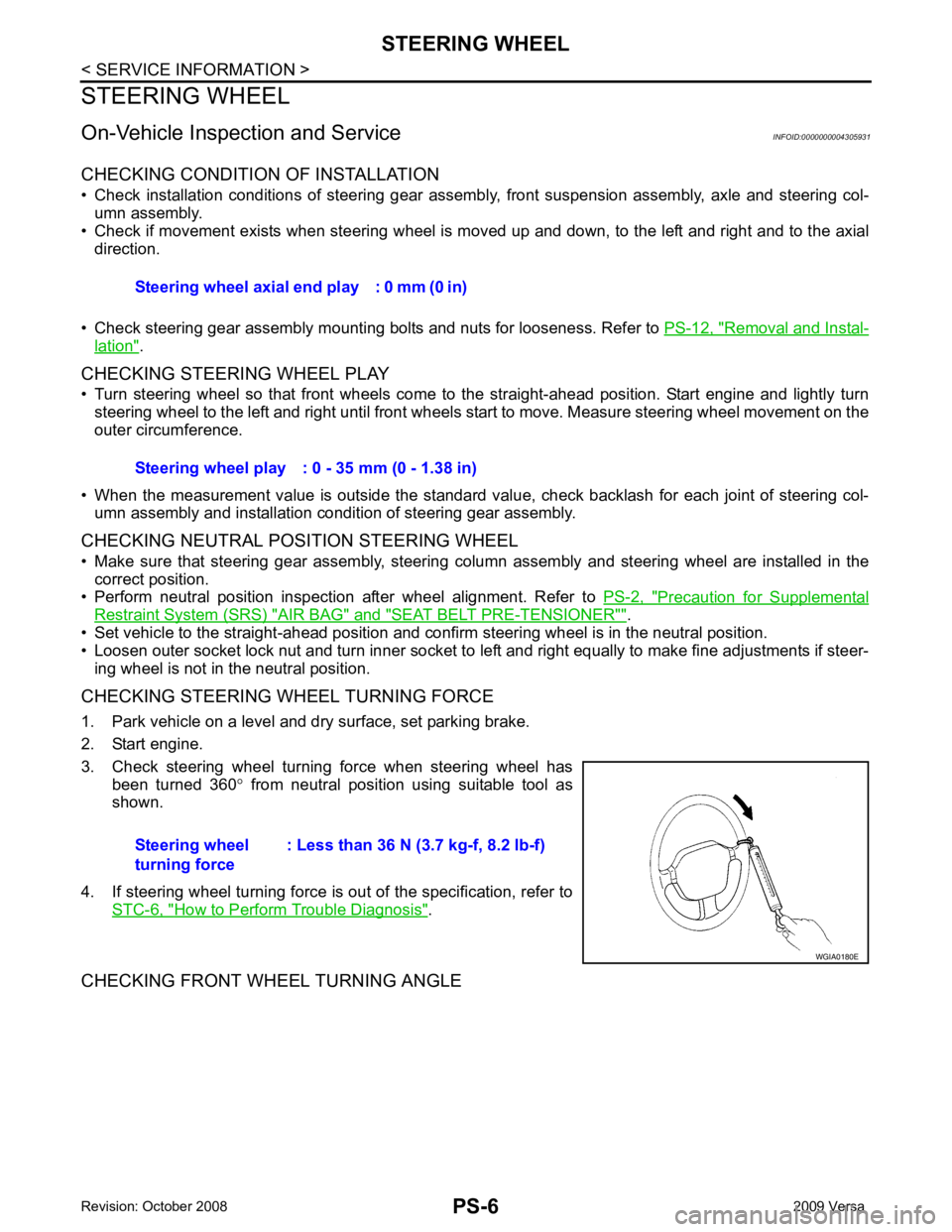
CHECKING STEERING WHEEL TURNING FORCE
1. Park vehicle on a level and dry surface, set parking brake.
2. Start engine.
3. Check steering wheel turning force when steering wheel has been turned 360 ° from neutral position using suitable tool as
shown.
4. If steering wheel turning force is out of the specification, refer to STC-6, " How to Perform Trouble Diagnosis " .
CHECKING FRONT WHEEL TURNING ANGLE Steering wheel axial end play : 0 mm (0 in)
Steering wheel play : 0 - 35 mm (0 - 1.38 in)
Steering wheel
turning force : Less than 36 N (3.7 kg-f, 8.2 lb-f)
Page 4082 of 4331
RF
N
O P
CONTENTS
ROOF
PRECAUTION ....... ........................................2
PRECAUTIONS .............................................. .....2
Precaution for Supplemental Restraint System
(SRS) "AIR BAG" and "SEAT BELT PRE-TEN-
SIONER" ............................................................. ......
2
Precaution Necessary fo r Steering Wheel Rota-
tion After Battery Disconnect ............................... ......
2
Precaution ........................................................... ......2
PREPARATION .... ........................................4
PREPARATION .............................................. .....4
Commercial Service Tool .................................... ......4
SYMPTOM DIAGNOSIS ..... ..........................5
SQUEAK AND RATTLE TROUBLE DIAG-
NOSES ........................ ........................................5
Work Flow ........................................................... ......5
Generic Squeak and Rattle Troubleshooting ...... ......7
Diagnostic Worksheet ......................................... ......9
FUNCTION DIAGNOSIS .. ............................11
TROUBLE DIAGNOSIS ................................. ....11 Component Parts and Harness Connector Loca-
tion ....................................................................... ....
11
System Description .............................................. ....11
CAN Communication System Description ........... ....13
Wiring Diagram - SROOF - .................................. ....14
Terminal and Reference Value for BCM ..................15
Terminal and Reference Value for Sunroof Motor
Assembly ............................................................. ....
16
Work Flow ............................................................ ....16
CONSULT-III Function (B CM) .................................16
Work Support ....................................................... ....17
Active Test ........................................................... ....17
Data Monitor ........................................................ ....17
Trouble Diagnosis Chart by Symptom ................. ....17
BCM Power Supply and Ground Circuit Inspection ....17
Sunroof Switch System Inspection ...................... ....17
Sunroof Motor Assembly Power Supply and
Ground Circuit Inspection .................................... ....
19
Door Switch Check .............................................. ....20
ON-VEHICLE REPAIR ..... ............................22
SUNROOF ......................................................... 22
Removal and Installation ..................................... ....22
Fitting Adjustment ................................................ ....27
Inspection ............................................................ ....28
Page 4293 of 4331
WW
N
O P
CONTENTS
WIPER, WASHER & HORN
SERVICE INFORMATION .. ..........................2
PRECAUTION ................................................ .....2
Precaution for Supplemental Restraint System
(SRS) "AIR BAG" and "SEAT BELT PRE-TEN-
SIONER" ............................................................. ......
2
Precaution for Procedure without Cowl Top Cover ......2
FRONT WIPER AND WASHER SYSTEM ..... .....3
Component Parts and Harness Connector Loca-
tion ...................................................................... ......
3
System Description ............................................. ......3
CAN Communication System Description ........... ......5
Schematic ........................................................... ......6
Wiring Diagram - WIPER - .................................. ......7
Terminal and Reference Value for BCM ............. ....10
Terminal and Reference Value for IPDM E/R ..... ....10
How to Proceed with Trouble Diagnosis ............. ....10
Preliminary Check ............................................... ....10
CONSULT-III Function (BCM) ............................. ....10
CONSULT-III Function (IPDM E/R) ..................... ....11
Front Wiper Does Not Operate ........................... ....12
Front Wiper Does Not Return to Stop Position (Af-
ter Front Wiper Operate for 10 Seconds, They
Stop for 20 Seconds, and After Repeating the Op-
eration Five Times, They Become Inoperative) .. ....
14
Only Front Wiper Low Does Not Operate ........... ....15
Only Front Wiper High Does Not Operate ........... ....16
Only Front Wiper Intermittent Does Not Operate .... 17
Front Wiper Intermittent Operation Switch Posi-
tion Cannot Be Adjusted ..................................... ....
18
Wiper Does Not Wipe When Front Washer Oper-
ates ..................................................................... ....
18
Front Wiper Does Not Stop ................................. ....18
Removal and Installation of Front Wiper Arms .... ....18
Adjustment of Wiper Arm Stop Location ............. ....19 Removal and Installation of Front Wiper Drive As-
sembly ................................................................. ....
20
Removal and Installation of Front Washer Nozzle ....20
Inspection for Washer No zzle ..................................21
Washer Nozzle Adjustment ................................. ....22
Washer Tube Layout ........................................... ....22
Removal and Installation of Front Wiper and
Washer Switch ..................................................... ....
23
Inspection of Front Wiper and Washer Switch Cir-
cuit ....................................................................... ....
23
Removal and Installation of Washer Tank ...............23
Removal and Installation of Front Washer Motor .... 24
REAR WIPER AND WASHER SYSTEM .......... 25
Component Parts and Harness Connector Loca-
tion ....................................................................... ....
25
System Description .............................................. ....25
Wiring Diagram - WIP/R - .................................... ....27
Terminal and Reference Value for BCM ..................29
How to Proceed with Trou ble Diagnosis ..................29
Preliminary Check ............................................... ....29
CONSULT-III Function (B CM) .................................29
Rear Wiper Does Not Operate ............................ ....29
Rear Wiper Stop Position Is Incorrect ................. ....30
Only Rear Wiper Does Not Operate .................... ....32
Only Rear Wiper Intermittent Does Not Operate . ....32
Wiper Does Not Wipe When Rear Washer Oper-
ates ...................................................................... ....
32
Removal and Installation ..................................... ....32
Washer Nozzle Adjustment ................................. ....35
POWER SOCKET ............................................. 36
Wiring Diagram - P/SCKT - ................................. ....36
Removal and Installation ..................................... ....36
HORN ................................................................ 38
Wiring Diagram - HORN - .................................... ....38
Removal and Installation ..................................... ....38