Page 1214 of 4331
CVT-270< SERVICE INFORMATION >
[RE0F08B]
DTC P0740 TORQUE CONVERTER CLUTCH SOLENOID VALVE
3. Check resistance between CVT unit harness connector terminal and ground.
4. If NG, replace the transaxle assembly. Refer to CVT-354," Removal and Installation " .
Solenoid Valve Connector Terminal
Resistance (Ap-
prox.)
Torque converter clutch sole-
noid valve F46 12 - Ground 3 - 9
Ω SCIA4684E
Page 1215 of 4331

CVT
N
O P
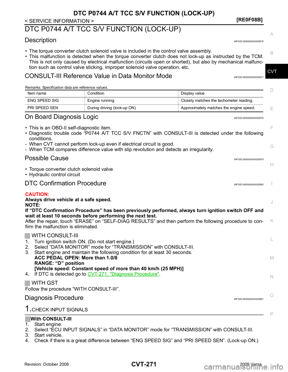
DTC P0744 A/T TCC S/V FUNCTION (LOCK-UP)
Description INFOID:0000000004305676
• The torque converter clutch solenoid valve is included in the control valve assembly.
• This malfunction is detected when the torque converter clutch does not lock-up as instructed by the TCM.
This is not only caused by electrical malfunction (cir cuits open or shorted), but also by mechanical malfunc-
tion such as control valve sticking, improper solenoid valve operation, etc.
CONSULT-III Reference Val ue in Data Monitor Mode INFOID:0000000004305677
Remarks: Specification data are reference values.
On Board Diagnosis Logic INFOID:0000000004305678
• This is an OBD-II self-diagnostic item.
• Diagnostic trouble code “P0744 A/T TCC S/V FNCTN” wit h CONSULT-III is detected under the following
conditions.
- When CVT cannot perform lock-up even if electrical circuit is good.
- When TCM compares difference value with slip revolution and detects an irregularity.
Possible Cause INFOID:0000000004305679
• Torque converter clutch solenoid valve
• Hydraulic control circuit
DTC Confirmation Procedure INFOID:0000000004305680
CAUTION:
Always drive vehicle at a safe speed.
NOTE:
If “DTC Confirmation Procedure” has been previously performed, alw ays turn ignition switch OFF and
wait at least 10 seconds before performing the next test.
After the repair, touch “ERASE” on “SELF-DIAG RESU LTS” and then perform the following procedure to con-
firm the malfunction is eliminated.
WITH CONSULT-III
1. Turn ignition switch ON. (Do not start engine.)
2. Select “DATA MONITOR” mode for “TRANSMISSION” with CONSULT-III.
3. Start engine and maintain the following condition for at least 30 seconds.
ACC PEDAL OPEN: More than 1.0/8
RANGE: “D” position
[Vehicle speed: Constant speed of more than 40 km/h (25 MPH)]
4. If DTC is detected go to CVT-271, " Diagnosis Procedure " .
WITH GST
Follow the procedure “WITH CONSULT-III”.
Diagnosis Procedure INFOID:0000000004305681
Page 1301 of 4331

CVT
N
O P
SERVICE DATA AND SPECIFICATIONS (SDS)
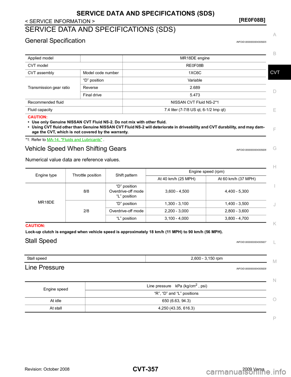
General Specification INFOID:0000000004305825
*1: Refer to MA-14, " Fluids and Lubricants " .
Vehicle Speed When Shifting Gears INFOID:0000000004305826
Numerical value data are reference values.
CAUTION:
Lock-up clutch is engaged when vehi cle speed is approximately 18 km/h (11 MPH) to 90 km/h (56 MPH).
Stall Speed INFOID:0000000004305827
Line Pressure INFOID:0000000004305828
Applied model
MR18DE engine
CVT model RE0F08B
CVT assembly Model code number 1XC6C
Transmission gear ratio “D” position Variable
Reverse 2.689
Final drive 5.473
Recommended fluid NISSAN CVT Fluid NS-2*1
Fluid capacity 7.4 liter (7-7/8 US qt, 6-1/2 Imp qt)
CAUTION:
• Use only Genuine NISSAN CVT Fluid NS-2. Do not mix with other fluid.
• Using CVT fluid other than Genuine NISSAN CVT Fluid NS-2 will deteriorate in driveability and CVT durability, and may dam- age the CVT, which is not covered by the warranty. Stall speed
2,600 - 3,150 rpmEngine speed
Line pressure kPa (kg/cm
2
, psi)
“R”, “D” and “L” positions
At idle 650 (6.63, 94.3)
At stall 4,250 (43.35, 616.3)
Page 1881 of 4331
EC
NP
O
RESUME OPERATION
When the RESUME/ACCELERATE swit ch is depressed after cancel operation other than depressing MAIN
switch is performed, vehicle speed will return to last set speed. To resume vehicle set speed, vehicle condition
must meet following conditions.
• Brake pedal is released.
• Clutch pedal is released (M/T models)
• Selector lever is in other than P and N positions (A/T and CVT models)
• Vehicle speed is greater than 40 km/h (25 MPH) and less than 144 km/h (89 MPH)
Component Description INFOID:0000000004537026
ASCD STEERING SWITCH Refer to EC-901 .
ASCD BRAKE SWITCH Refer to EC-907 and
EC-973 .
ASCD CLUTCH SWITCH Refer to EC-907 and
EC-973 .
STOP LAMP SWITCH Refer to EC-907 ,
EC-921 and
EC-973 .
ELECTRIC THROTTLE CONTROL ACTUATOR Refer to EC-925 ,
EC-929 ,
EC-935 and
EC-940 .
ASCD INDICATOR Refer to EC-981 .
Page 1949 of 4331
EC
NP
O
1. Stop lamp switch 2. ASCD brake switch 3. ASCD clutch switch
4. Clutch pedal 5. ASCD steering switch 6. MAIN switch
7. CANCEL switch 8. SET/COAST switch 9. RESUME/ACCELERATOR switch
10. EVAP control system pressure sen- sor 11. EVAP canister 12. EVAP canister vent control valve
Page 1959 of 4331
![NISSAN LATIO 2009 Service Repair Manual EC
NP
O
: Average voltage for pulse signal (Actual pulse signal can be confirmed by oscilloscope.) 94 R ASCD steering switch
[Ignition switch: ON]
• ASCD steering switch: OFF Approximately 4V
[Ignit NISSAN LATIO 2009 Service Repair Manual EC
NP
O
: Average voltage for pulse signal (Actual pulse signal can be confirmed by oscilloscope.) 94 R ASCD steering switch
[Ignition switch: ON]
• ASCD steering switch: OFF Approximately 4V
[Ignit](/manual-img/5/57359/w960_57359-1958.png)
EC
NP
O
: Average voltage for pulse signal (Actual pulse signal can be confirmed by oscilloscope.) 94 R ASCD steering switch
[Ignition switch: ON]
• ASCD steering switch: OFF Approximately 4V
[Ignition switch: ON]
• MAIN switch: Pressed Approximately 0V
[Ignition switch: ON]
• CANCEL switch: Pressed Approximately 1V
[Ignition switch: ON]
• RESUME/ACCELERATE switch: Pressed Approximately 3V
[Ignition switch: ON]
• SET/COAST switch: Pressed Approximately 2V
95 B Sensor ground
(ASCD steering switch) [Engine is running]
• Warm-up condition
• Idle speed Approximately 0V
99 R Stop lamp switch [Ignition switch: OFF]
• Brake pedal: Fully released Approximately 0V
[Ignition switch: OFF]
• Brake pedal: Slightly depressed BATTERY VOLTAGE
(11 - 14V)
100 G ASCD brake switch [Ignition switch: ON]
• Brake pedal: Slightly depressed (A/T, CVT)
• Brake pedal and/or clutch pedal: Slightly de-
pressed (M/T) Approximately 0V
[Ignition switch: ON]
• Brake pedal: Fully released (A/T, CVT)
• Brake pedal and clutch pedal: Fully re-
leased (M/T) BATTTERY VOLTAGE
(11 - 14V)
102 SB Sensor power supply
(Accelerator pedal position
sensor 2) [Ignition switch: ON]
Approximately 5V
103 GR Accelerator pedal position
sensor 2 [Ignition switch: ON]
• Engine stopped
• Accelerator pedal: Fully released 0.3 - 0.6V
[Ignition switch: ON]
• Engine stopped
• Accelerator pedal: Fully depressed 1.95 - 2.4V
104 Y Sensor ground
(Accelerator pedal position
sensor 2) [Engine is running]
• Warm-up condition
• Idle speed Approximately 0V
105 G Power supply for ECM [Ignition switch: ON]BATTERY VOLTAGE
(11 - 14V)
106 P Sensor power supply
(Accelerator pedal position
sensor 1) [Ignition switch: ON]
Approximately 5V
108 B ECM ground [Engine is running]
• Idle speed Body ground
110 G Accelerator pedal position
sensor 1 [Ignition switch: ON]
• Engine stopped
• Accelerator pedal: Fully released 0.6 - 0.9V
[Ignition switch: ON]
• Engine stopped
• Accelerator pedal: Fully depressed 3.9 - 4.7V
111 R Sensor ground
(Accelerator pedal position
sensor 1) [Engine is running]
• Warm-up condition
• Idle speed Approximately 0V
TERMI-
NAL
NO. WIRE
COLOR ITEM CONDITION DATA (DC Voltage)
Page 1961 of 4331

EC
NP
O
Item
DIAGNOSTIC TEST MODE
WORK SUP-
PORT SELF DIAGNOSTIC
RESULT DATA
MONI-
TOR ACTIVE
TEST DTC & SRT
CONFIRMATION
DTC* 1 FREEZE
FRAME
DATA* 2 SRT
STATUS DTC
WORK
SUP-
PORTENGINE CONTROL COMPONENT PARTS
INPUT
Crankshaft position sensor (POS) × × ×
Camshaft position sensor (PHASE) × × ×
Mass air flow sensor × ×
Engine coolant temperature sensor × × × ×
Air fuel ratio (A/F) sensor 1 × × × ×
Heated oxygen sensor 2 × × × ×
Vehicle speed signal × × ×
Accelerator pedal position sensor × ×
Throttle position sensor × × ×
Fuel tank temperature sensor × × ×
EVAP control system pressure sen-
sor × ×
Intake air temperature sensor × × ×
Knock sensor ×
Refrigerant pressure sensor ×
Closed throttle position switch (Ac-
celerator pedal position sensor sig-
nal) ×
Air conditioner switch ×
Park/neutral position (PNP) switch × ×
Stop lamp switch × ×
Battery voltage ×
Load signal ×
Fuel level sensor × ×
ASCD steering switch × ×
ASCD brake switch × ×
ASCD clutch switch × ×
Power steering operation signal ×
Page 2263 of 4331

EC
NP
O
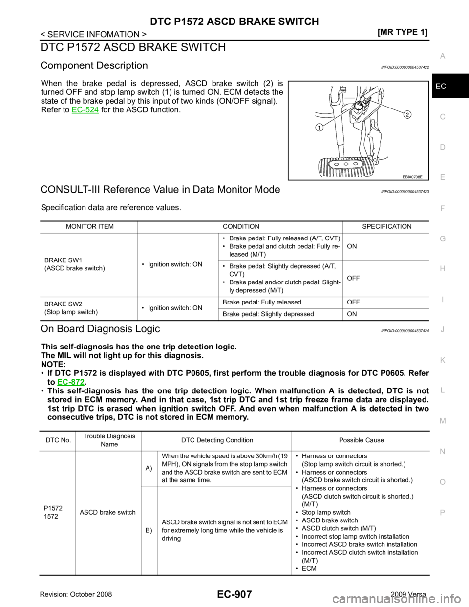
DTC P1572 ASCD BRAKE SWITCH
Component Description INFOID:0000000004537422
When the brake pedal is depressed, ASCD brake switch (2) is
turned OFF and stop lamp switch (1) is turned ON. ECM detects the
state of the brake pedal by this input of two kinds (ON/OFF signal).
Refer to EC-524 for the ASCD function.
CONSULT-III Reference Val ue in Data Monitor Mode INFOID:0000000004537423
Specification data are reference values.
On Board Diagnosis Logic INFOID:0000000004537424
This self-diagnosis has the on e trip detection logic.
The MIL will not light up for this diagnosis.
NOTE:
• If DTC P1572 is displayed with DT C P0605, first perform the trouble diagnosis for DTC P0605. Refer
to EC-872 .
• This self-diagnosis has the one trip detection logic. When malfunction A is detected, DTC is not
stored in ECM memory. And in that case, 1st trip DTC and 1st trip freeze frame data are displayed.
1st trip DTC is erased when igniti on switch OFF. And even when ma lfunction A is detected in two
consecutive trips, DTC is not stored in ECM memory. DTC No.
Trouble Diagnosis
Name DTC Detecting Condition Possible Cause
P1572
1572 ASCD brake switch A)
When the vehicle speed is above 30km/h (19
MPH), ON signals from the stop lamp switch
and the ASCD brake switch are sent to ECM
at the same time. • Harness or connectors
(Stop lamp switch circuit is shorted.)
• Harness or connectors (ASCD brake switch circuit is shorted.)
• Harness or connectors
(ASCD clutch switch circuit is shorted.)
(M/T)
• Stop lamp switch
• ASCD brake switch
• ASCD clutch switch (M/T)
• Incorrect stop lamp switch installation
• Incorrect ASCD brake switch installation
• Incorrect ASCD clutch switch installation (M/T)
• ECM
B)
ASCD brake switch signal is not sent to ECM
for extremely long time while the vehicle is
driving