Page 891 of 4331

CL
N
O P
CLUTCH DISC, CLUTCH COVER AND FLYWHEEL
Removal and Installation INFOID:0000000004305174
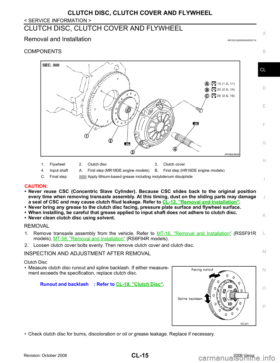
COMPONENTS
CAUTION:
• Never reuse CSC (Concentric Slave Cylinder). B ecause CSC slides back to the original position
every time when removing transaxle assembly. At th is timing, dust on the sliding parts may damage
a seal of CSC and may cause clut ch fliud leakage. Refer to CL-12, " Removal and Installation " .
• Never bring any grease to the clutch disc faci ng, pressure plate surface and flywheel surface.
• When installing, be careful that grease applied to input shaft does not adhere to clutch disc.
• Never clean clutch disc using solvent.
REMOVAL 1. Remove transaxle assembly from the vehicle. Refer to MT-16, " Removal and Installation " (RS5F91R
models), MT-58, " Removal and Installation " (RS6F94R models).
2. Loosen clutch cover bolts evenly. Then remove clutch cover and clutch disc.
INSPECTION AND ADJUSTMENT AFTER REMOVAL
Clutch Disc • Measure clutch disc runout and spline backlash. If either measure- ment exceeds the specificat ion, replace clutch disc.
• Check clutch disc for burns, discoloration or oil or grease leakage. Replace if necessary.
1. Flywheel 2. Clutch disc 3. Clutch cover
4. Input shaft A. First step (MR18DE engine models) B. First step (HR16DE engine models)
C. Final step Apply lithium-based grease including molybdenum disulphide Clutch Disc " .
Page 892 of 4331
Inspection "
(HR16DE models),
EM-216, " Inspection After Disassembly "
(MR18DE models).
CAUTION:
Measure flywheel outer face (not on knock pin and clutch cover
mounting hole).
INSTALLATION
1. Clean clutch disc and input shaft splines to remove grease and dust caused by abrasion.
2. Apply recommended grease to clutch disc and input shaft splines. CAUTION:
Be sure to apply grease to the points specified. Ot herwise, noise, poor disengagement, or damage
to the clutch may result. Excessive grease may cause sl ip or shudder. If it adheres to CSC seal, it
will cause clutch fluid l eakage. Wipe off excess grease.
Clutch facing wear : Refer to
CL-18, " Clutch Disc " .
Clutch
Cover " .
Tool number A : ST20050240 ( — )
Page 893 of 4331
CL
N
O P
3. Install clutch disc using suitable clutch aligner (A).
• B: HR16DE
• C: MR18DE
4. Install clutch cover. Pre-tighten clutch cover bolts.
5. Tighten clutch cover bolts evenly in two steps in the order shown.
6. Install transaxle assembly. Refer to MT-58, " Removal and Instal-
lation " .
Page 894 of 4331

Clearance (A) between clutch pedal and ASCD switch threaded
end while clutch pedal is fully released (if equipped). 0.74 - 1.96 mm (0.0291 - 0.0772 in)
Clearance (C) between clutch pedal and clutch interlock switch
threaded end while clutch pedal is fully depressed. 0.74 - 1.96 mm (0.0291 - 0.0772 in)Engine type HR16DE MR18DE
Model 200 225
Facing size (outer dia. × inner dia. × thickness) 200 mm x 140 mm x 3.1 mm (7.87 in x
5.51 in x 0.122 in) 225 mm
× 160 mm × 3.2 mm (8.86 in ×
6.30 in × 0.126 in)
Thickness of disc assembly with load 7.1 - 7.5 mm (0.280 - 0.295 in) with 4,658
N (475 kg, 1,047 lb) 7.2 - 7.6 mm (0.283 - 0.299 in) with
5,394 N (550 kg, 1,213 lb)
Runout limit/diameter of the area to be measured 1.0 mm (0.039 in) / 190 mm (7.48 in) dia 1.0 mm (0.039 in) / 215 mm (8.46 in)
dia.
Maximum spline backlash (at outer edge of disc) 0.8 mm (0.031 in) 0.9 mm (0.035 in)
Wear limit of facing (depth to the rivet head) 0.3 mm (0.012 in) 0.3 mm (0.012 in) Engine type HR16DE MR18DE
Set-load 4,658 N (475.1 kg, 1,047.1 lb) 5,394 N (550 kg, 1,213 lb)
Diaphragm spring lever height 29 - 31 mm (1.14 - 1.22 in) 20 - 22 mm (0.79 - 0.87 in)
Uneven limit of diaphragm spring toe height 0.7 mm (0.028 in) or less 0.7 mm (0.028 in) or less
Page 959 of 4331
![NISSAN LATIO 2009 Service Repair Manual PRECAUTIONS
CVT-15
< SERVICE INFORMATION >
[RE0F08A] D
E
F
G H
I
J
K L
M A
B CVT
N
O P
•
Before replacing TCM, perform TCM input/output signal
inspection and make sure whether TCM functions pr NISSAN LATIO 2009 Service Repair Manual PRECAUTIONS
CVT-15
< SERVICE INFORMATION >
[RE0F08A] D
E
F
G H
I
J
K L
M A
B CVT
N
O P
•
Before replacing TCM, perform TCM input/output signal
inspection and make sure whether TCM functions pr](/manual-img/5/57359/w960_57359-958.png)
PRECAUTIONS
CVT-15
< SERVICE INFORMATION >
[RE0F08A] D
E
F
G H
I
J
K L
M A
B CVT
N
O P
•
Before replacing TCM, perform TCM input/output signal
inspection and make sure whether TCM functions properly or
not. CVT-49, " TCM Terminal and Reference Value " .
• After performing each TROUBL E DIAGNOSIS, perform “DTC
Confirmation Procedure”.
If the repair is completed the DTC should not be displayed in
the “DTC Confirmation Procedure”.
• Always use the specified br and of CVT fluid. Refer to MA-14, " Flu-
ids and Lubricants " .
• Use lint-free paper, not cloth rags, during work.
• After replacing the CVT fluid, dispose of the waste oil using the methods prescribed by law, ordinance, etc.
Service Notice or Precaution INFOID:0000000004666859
CVT FLUID COOLER SERVICE If CVT fluid contains friction material (clutches, brakes , etc.), or if an CVT is replaced, inspect and clean the
CVT fluid cooler mounted in the radiator or replace t he radiator. Flush cooler lines using cleaning solvent and
compressed air after repair. For CVT fluid cooler cleaning procedure, refer to CVT-18, " CVT Fluid Cooler
Cleaning " . For radiator replacement, refer to
CO-38 .
OBD-II SELF-DIAGNOSIS • CVT self-diagnosis is performed by the TCM in comb ination with the ECM. The results can be read through
the blinking pattern of the malfunction indi cator lamp (MIL). Refer to the table on CVT-51, " CONSULT-III
Function (TRANSMISSION) " for the indicator used to display each self-diagnostic result.
• The self-diagnostic results indicated by the MIL ar e automatically stored in both the ECM and TCM memo-
ries.
Always perform the procedure on CVT-30, " OBD-II Diagnostic Trouble Code (DTC) " to complete the
repair and avoid unnecessary blinking of the MIL.
For details of OBD-II, refer to EC-541, " Introduction " .
• Certain systems and components, especially those re lated to OBD, may use the new style slide-lock-
ing type harness connector. For descripti on and how to disconnect, refer to PG-64 . MEF040DA
SEF217U
Page 962 of 4331

Checking CVT Fluid " .
CAUTION:
Delete CVT fluid deterioration date with CONS ULT-III after changing CVT fluid. Refer to CVT-51," CONSULT-III Function (TRANSMISSION) " .
CVT Fluid Cooler Cleaning INFOID:0000000004666864
Whenever a CVT is repaired, overhauled, or replaced, t he CVT fluid cooler mounted in the radiator must be
inspected and cleaned.
Metal debris and friction material, if present, can be tr apped or become deposit in the CVT fluid cooler. This
debris can contaminate the newly serviced CVT or, in severe cases, can block or restrict the flow of CVT fluid.
In either case, malfunction of the newly serviced CVT may occur.
Debris, if present, may deposit as CVT fluid enters the cooler inlet. It will be necessary to back flush the cooler
through the cooler outlet in order to flush out any built up debris.
CVT FLUID COOLER CLEANING PROCEDURE
1. Identify the CVT inlet and outlet fluid cooler hoses.
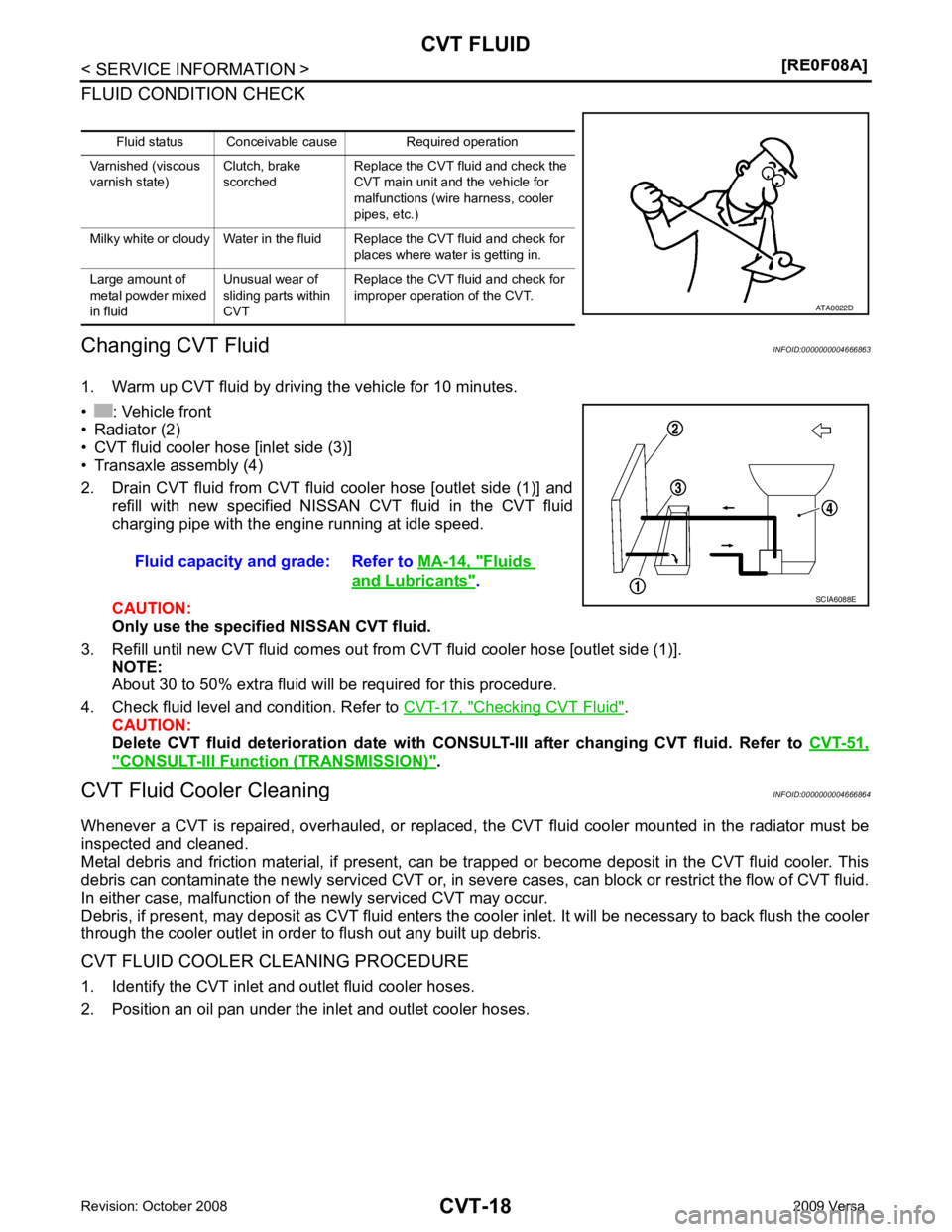
2. Position an oil pan under the inlet and outlet cooler hoses. Fluid status Conceivable cause Required operation
Varnished (viscous
varnish state) Clutch, brake
scorched Replace the CVT fluid and check the
CVT main unit and the vehicle for
malfunctions (wire harness, cooler
pipes, etc.)
Milky white or cloudy Water in the fluid Replace the CVT fluid and check for places where water is getting in.
Large amount of
metal powder mixed
in fluid Unusual wear of
sliding parts within
CVT Replace the CVT fluid and check for
improper operation of the CVT. Fluids
and Lubricants " .
Page 965 of 4331
CVT
N
O P
b. If one or more pieces of debr
is are found that are over 1 mm
(0.040 in) in size and/or peeled clutch facing material is found in
the coffee filter, the fluid cooler is not serviceable. The radiator/
fluid cooler must be replaced and the inspection procedure is
ended.
CVT FLUID COOLER FINAL INSPECTION After performing all procedures, ensure that all remaining oil is cleaned from all components.
Page 973 of 4331
CVT
N
O P
Lock-up and Select Control System Diagram
Lock-up Released In the lock-up released state, the torque converter clutch control valve is set into the unlocked state by the
torque converter clutch solenoid and the lock-up apply pressure is drained.
In this way, the torque converter clutch piston is not coupled.
Lock-up Applied In the lock-up applied state, the torque converter clutch control valve is set into the locked state by the torque
converter clutch solenoid and lock-up apply pressure is generated.
In this way, the torque converter clutch piston is pressed and coupled.
Select Control When shifting between “N” (“P”) ⇔“D” (“R”), optimize the operating pressure on the basis of the throttle posi-
tion, the engine speed, and the secondary pulley (out put) revolution speed to lessen the shift shock.
Control Valve INFOID:0000000004666874
FUNCTION OF CONTROL VALVE