Page 4143 of 4331

SC
N
O P
CHARGING THE BATTERY
CAUTION:
• Do not “quick charge” a fully discharged battery.
• Keep the battery away from open flame while it is being charged.
• When connecting the charger, connect the leads first, then turn on the charger. Do not turn on the
charger first, as this may cause a spark.
• If battery electrolyte temperature rises above 55 °C (131 °F), stop charging. Alw ays charge battery at a
temperature below 55 °C (131 °F).
Charging Rates
Do not charge at more than 50 ampere rate.
NOTE:
The ammeter reading on your battery charger will automat ically decrease as the battery charges. This indi-
cates that the voltage of the battery is increasing norma lly as the state of charge improves. The charging amps
indicated above refer to initial charge rate.
• If, after charging, the specific gravity of any two ce lls varies more than 0.050, the battery should be replaced.
Trouble Diagnosis with Battery Service Center INFOID:0000000004306819
For battery testing, use Battery Serv ice Center (J-48087). For details and operating instructions, refer to Tech-
nical Service Bulletin and/or Battery Service Center User Guide.
Removal and Installation INFOID:0000000004306820
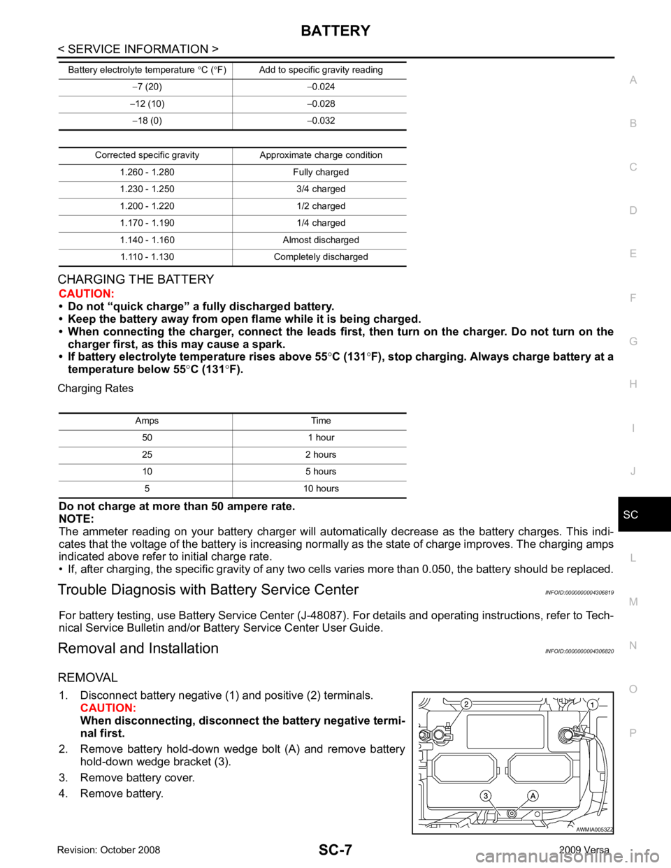
REMOVAL 1. Disconnect battery negative (1) and positive (2) terminals. CAUTION:
When disconnecting, disconnect the battery negative termi-
nal first.
2. Remove battery hold-down wedge bolt (A) and remove battery hold-down wedge bracket (3).
3. Remove battery cover.
4. Remove battery. −
7 (20) −0.024
− 12 (10) −0.028
− 18 (0) −0.032
Corrected specific gravity Approximate charge condition 1.260 - 1.280 Fully charged
1.230 - 1.250 3/4 charged
1.200 - 1.220 1/2 charged
1.170 - 1.190 1/4 charged
1.140 - 1.160 Almost discharged 1.110 - 1.130 Completely discharged
Battery electrolyte temperature
°C ( °F) Add to specific gravity reading Amps Time
50 1 hour
25 2 hours
10 5 hours 5 10 hours
Page 4163 of 4331

SC
N
O P
SERVICE DATA AND SPECIFICATIONS (SDS)
Battery INFOID:0000000004306829
Starter INFOID:0000000004306830
Generator INFOID:0000000004306831
MT, A/T CVT
Type T4 Gr.51 R
20 hours rate capacity 12 V - 47 AH 12 V - 43 AH
Cold Cranking Am ps. (CCA) 470 410Applied model HR16DE MR18DE
Type S114_901A S114 - 902B
HITACHI make HITACHI make
Reduction gear type Reduction gear type
System voltage 12 V 12 V
No-load Terminal voltage 11 V 11 V
Current Less than 110 A Less than 110 A
Revolution More than 3,000 rpm More than 3,000 rpm Applied model HR16DE MR18DE
Type A2TJ0291Z A2TG1581Z
MITSUBISHI make MITSUBISHI make
Nominal rating 12 V - 100 A 12 V - 100 A
Ground polarity Negative Negative
Minimum revolution under no-load (when 13.5 V is
applied) Less than 1,000 rpm Less than 1,000 rpm
Hot output current (when 13.5 V is applied) More than 27 A/1,300 rpm
More than 95 A/2,500 rpm
More than 116 A/5,000 rpm More than 16 A/1,300 rpm
More than 82 A/2,500 rpm
More than 97 A/5,000 rpm
Regulated output voltage 14.1 - 14.7 V 14.1 - 14.7 V
Page 4164 of 4331

SE
N
O P
CONTENTS
SEAT
SERVICE INFORMATION .. ..........................2
PRECAUTIONS .............................................. .....2
Precaution for Supplemental Restraint System
(SRS) "AIR BAG" and "SEAT BELT PRE-TEN-
SIONER" ............................................................. ......
2
Precaution Necessary fo r Steering Wheel Rota-
tion After Battery Disconnect ............................... ......
2
Service Notice ..................................................... ......2
Precaution ........................................................... ......3
PREPARATION .............................................. .....4
Special Service Tool ........................................... ......4
Commercial Service Tool .................................... ......4
SQUEAK AND RATTLE TROUBLE DIAG-
NOSES ........................ ........................................5
Work Flow ........................................................... ......5 Generic Squeak and Rattle Troubleshooting .......
.....7
Diagnostic Worksheet .......................................... .....9
FRONT SEAT .................................................... 11
Driver Seat ........................................................... ....11
Passenger Seat ................................................... ....12
Removal and Installation ..................................... ....12
Disassembly and Assembly ................................. ....13
REAR SEAT ...................................................... 15
Component Parts Drawing .................................. ....15
Removal and Installation ..................................... ....16
Disassembly and Assembly ................................. ....18
Component Parts Drawing .................................. ....21
Removal and Installation ..................................... ....22
Disassembly and Assembly ................................. ....24
Removal and Installation ..................................... ....26
Disassembly and Assembly ................................. ....26
Page 4167 of 4331
SE-4< SERVICE INFORMATION >
PREPARATION
PREPARATION
Special Service Tool INFOID:0000000004306502
The actual shapes of Kent -Moore tools may differ from those of special service tools illustrated here.
Commercial Service Tool INFOID:0000000004306503
Tool number
(Kent-Moore No.)
Tool name Description
—
(J-39570)
Chassis ear Locating the noise
—
(J-43980)
NISSAN Squeak and Rattle
Kit Repairing the cause of noise SIIA0993E
SIIA0994E
(Kent-Moore No.)
Tool name Description
(J-39565)
Engine ear Locating the noiseSIIA0995E
Page 4168 of 4331

SQUEAK AND RATTLE TROUBLE DIAGNOSES
SE-5
< SERVICE INFORMATION >
C
D E
F
G H
J
K L
M A
B SE
N
O P
SQUEAK AND RATTLE TROUBLE DIAGNOSES
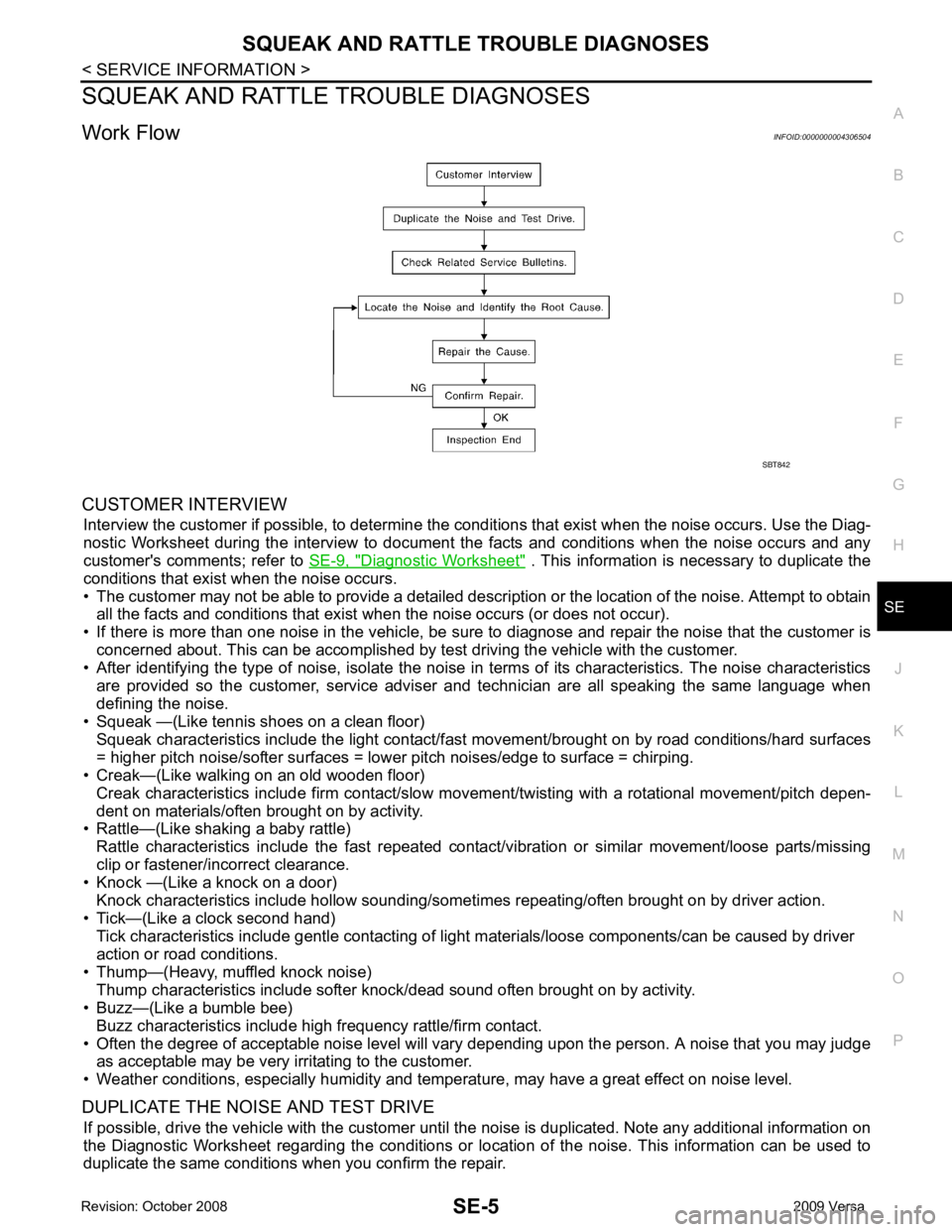
Work Flow INFOID:0000000004306504
CUSTOMER INTERVIEW Interview the customer if possible, to determine the c onditions that exist when the noise occurs. Use the Diag-
nostic Worksheet during the interv iew to document the facts and conditions when the noise occurs and any
customer's comments; refer to SE-9, " Diagnostic Worksheet " . This information is necessary to duplicate the
conditions that exist when the noise occurs.
• The customer may not be able to provide a detailed descr iption or the location of the noise. Attempt to obtain
all the facts and conditions that exist when the noise occurs (or does not occur).
• If there is more than one noise in the vehicle, be sure to diagnose and repair the noise that the customer is
concerned about. This can be accomplished by test driving the vehicle with the customer.
• After identifying the type of noise, isolate the noise in terms of its characteristics. The noise characteristics
are provided so the customer, service adviser and technician are all speaking the same language when
defining the noise.
• Squeak —(Like tennis shoes on a clean floor)
Squeak characteristics include the light contact/fast movement/brought on by road conditions/hard surfaces
= higher pitch noise/softer surfaces = lower pitch noises/edge to surface = chirping.
• Creak—(Like walking on an old wooden floor)
Creak characteristics include firm contact/slow mo vement/twisting with a rotational movement/pitch depen-
dent on materials/often brought on by activity.
• Rattle—(Like shaking a baby rattle)
Rattle characteristics include the fast repeated contac t/vibration or similar movement/loose parts/missing
clip or fastener/incorrect clearance.
• Knock —(Like a knock on a door)
Knock characteristics include hollow sounding/someti mes repeating/often brought on by driver action.
• Tick—(Like a clock second hand) Tick characteristics include gentle contacting of li ght materials/loose components/can be caused by driver
action or road conditions.
• Thump—(Heavy, muffled knock noise) Thump characteristics include softer k nock/dead sound often brought on by activity.
• Buzz—(Like a bumble bee)
Buzz characteristics include high frequency rattle/firm contact.
• Often the degree of acceptable noise level will vary depending upon the person. A noise that you may judge as acceptable may be very irritating to the customer.
• Weather conditions, especially humidity and temperature, may have a great effect on noise level.
DUPLICATE THE NOISE AND TEST DRIVE If possible, drive the vehicle with the customer until the noise is duplicated. Note any additional information on
the Diagnostic Worksheet regarding the conditions or lo cation of the noise. This information can be used to
duplicate the same conditions when you confirm the repair. SBT842
Page 4172 of 4331
SQUEAK AND RATTLE TROUBLE DIAGNOSES
SE-9
< SERVICE INFORMATION >
C
D E
F
G H
J
K L
M A
B SE
N
O P
Diagnostic Worksheet
INFOID:0000000004306506 LAIA0072E
Page 4173 of 4331
SE-10< SERVICE INFORMATION >
SQUEAK AND RATTLE TROUBLE DIAGNOSES LAIA0071E
Page 4185 of 4331

SE-22< SERVICE INFORMATION >
REAR SEAT
Removal and Installation INFOID:0000000004306515
CAUTION:
When removing and in stalling, use shop cloths to protect parts from damage.
60:40 SPLIT FOLD DOWN SEAT - SEDAN
Removal
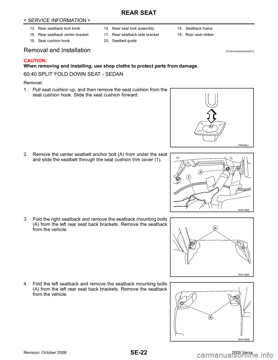
1. Pull seat cushion up, and then remove the seat cushion from the seat cushion hook. Slide the seat cushion forward.
2. Remove the center seatbelt anchor bolt (A) from under the seat and slide the seatbelt through the seat cushion trim cover (1).
3. Fold the right seatback and remove the seatback mounting bolts (A) from the left rear seat back brackets. Remove the seatback
from the vehicle.
4. Fold the left seatback and remove the seatback mounting bolts (A) from the left rear seat back brackets. Remove the seatback
from the vehicle.
13. Rear seatback lock knob 14. Rear seat lock assembly 15. Seatback frame
16. Rear seatback center bracket 17. Rear seatback side bracket 18. Rear seat striker
19. Seat cushion hook 20. Seatbelt guide PIIB4085J
WIIA1380E
WIIA1382E
WIIA1383E