Page 4115 of 4331
RSU-4< SERVICE INFORMATION >
PREPARATION
PREPARATION
Commercial Service Tool INFOID:0000000004305876
Tool name Description
Power tool Removing nuts, bolts and screws PIIB1407E
Page 4117 of 4331
.
3. Wheel bearing axial end play. Refer to RAX-5, " On-Vehicle Inspection and Service " .
4. Shock absorber operation.
5. Each mounting part of suspension for looseness and deformation.
6. Rear suspension beam for cracks, deformation, and other damage.
7. Vehicle height (posture).
GENERAL INFORMATION AND RECOMMENDATIONS
1. A Four-Wheel Thrust Alignment should be performed. • This type of alignment is recommended for any NISSAN vehicle.
• The four-wheel “thrust” process helps ensure that the vehicle is properly aligned and the steering wheel
is centered.
• The alignment machine itself should be ca pable of accepting any NISSAN vehicle.
• The alignment machine should be checked to ensure that it is level.
2. Make sure the alignment machine is properly calibrated. • Your alignment machine should be regularly calibrated in order to give correct information.
• Check with the manufacturer of your specific al ignment machine for their recommended Service/Cali-
bration Schedule.
THE ALIGNMENT PROCESS
IMPORTANT: Use only the alignment specifications listed in this Service Manual. Refer to RSU-13, " Wheel
Alignment (Unladen*) " .
1. When displaying the alignment settings, many alignm ent machines use “indicators”: (Green/red, plus or
minus, Go/No Go). Do NOT use these indicators.
• The alignment specifications programmed into your alignment machine that operate these indicators
may not be correct.
• This may result in an ERROR.
2. Some newer alignment machines are equipped with an optional “Rolling Compensation” method to “com- pensate” the sensors (alignment targets or head units). Do NOT use this “Rolling Compensation”
method.
• Use the “Jacking Compensation” method. After inst alling the alignment targets or head units, raise the
vehicle and rotate the wheels 1/2 turn both ways.
• See Instructions in the alignment machine you are using for more information.
CAMBER INSPECTION
Page 4122 of 4331
COIL SPRING
RSU-11
< SERVICE INFORMATION >
C
D
F
G H
I
J
K L
M A
B RSU
N
O P
COIL SPRING
Removal and Installation INFOID:0000000004305882
REMOVAL 1. Remove wheel and tire using power tool.
2. Remove wheel sensor from wheel hub and bearing assembly. Refer to BRC-32, " Removal and Installa-
tion " .
CAUTION:
Do not pull on wheel sensor harness.
3. Separate brake tube from wheel cylinder. Refer to BR-12, " Rear Brake Tube and Hose " .
4. Set jack under rear suspension beam.
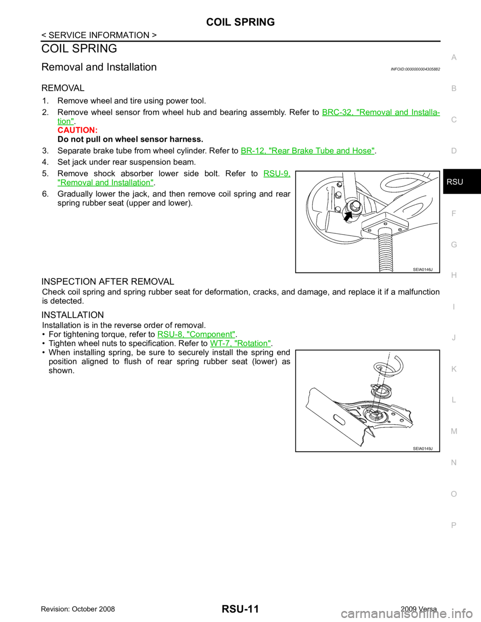
5. Remove shock absorber lower side bolt. Refer to RSU-9," Removal and Installation " .
6. Gradually lower the jack, and then remove coil spring and rear spring rubber seat (upper and lower).
INSPECTION AFTER REMOVAL Check coil spring and spring rubber seat for deformation, cracks, and damage, and replace it if a malfunction
is detected.
INSTALLATION Installation is in the reverse order of removal.
• For tightening torque, refer to RSU-8, " Component " .
• Tighten wheel nuts to specification. Refer to WT-7, " Rotation " .
• When installing spring, be sure to securely install the spring end
position aligned to flush of rear spring rubber seat (lower) as
shown. SEIA0146J
SEIA0149J
Page 4123 of 4331
On-
Vehicle Service " .
3. Remove wheel sensor and wheel sensor harness from wheel hub and bearing assembly and rear suspen-
sion beam. Refer to BRC-32, " Removal and Installation " .
4. Remove lock plate and separate brake tube from brake hose. Refer to BR-12, " Rear Brake Tube and Hose " .
5. Remove wheel hub and bearing assembly and back plate. Refer to RAX-5, " On-Vehicle Inspection and Service " .
6. Set jack under rear suspension beam.
7. Remove coil spring (left/right). Refer to RSU-11, " Removal and
Installation " .
8. Remove bolts between body and rear suspension beam bracket. Refer to RSU-8, " Component " .
9. Gradually lower the jack, and then remove rear suspension beam from vehicle.
10. Remove the rear suspension beam bracket bolt and nut, and then remove rear suspension beam bracket
from rear suspension beam. Refer to RSU-8, " Component " .
11. Remove brake tube protector from rear suspension beam.
INSPECTION AFTER REMOVAL
Check components for deformation, cracks, and other damage, and replace if necessary.
INSTALLATION
Installation is in the reverse order of removal.
• For tightening torque, refer to RSU-8, " Component " .
• Refill with new brake fluid and bleed air. Refer to BR-9, " Bleeding Brake System " .
• Tighten wheel nuts to specification. Refer to WT-7, " Rotation " .
• Check the following after finishing work.
- Parking brake operation (stroke): Refer to PB-5, " On-Vehicle Service " .
- Wheel sensor harness for proper connection: Refer to BRC-32, " Removal and Installation " .
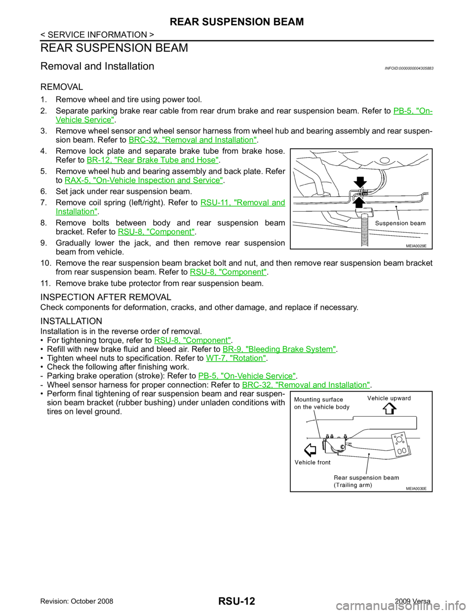
• Perform final tightening of rear suspension beam and rear suspen-
sion beam bracket (rubber bushing) under unladen conditions with
tires on level ground. MEIA0030E
Page 4124 of 4331
RSU
N
O P
SERVICE DATA AND SPECIFICATIONS (SDS)
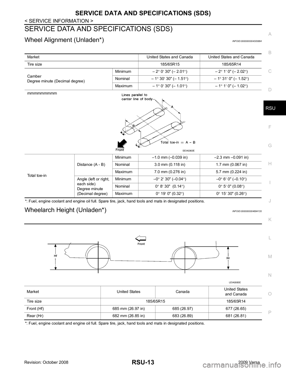
Wheel Alignment (Unladen*) INFOID:0000000004305884
*: Fuel, engine coolant and engine oil full. Spare tire, jack, hand tools and mats in designated positions.
Wheelarch Height (Unladen*) INFOID:0000000004884135
*: Fuel, engine coolant and engine oil full. Spare tire, jack, hand tools and mats in designated positions. Market United States and Canada United States and Canada
Tire size 185/65R15 185/65R14
Camber
Degree minute (Decimal degree) Minimum – 2
° 0 ′ 30" (– 2.01 °) – 2 ° 1 ′ 0" (– 2.02 °)
Nominal – 1 ° 30 ′ 30" (– 1.51 °) – 1 ° 31 ′ 0" (– 1.52 °)
Maximum – 1 ° 0 ′ 30" (– 1.01 °) – 1 ° 1 ′ 0" (– 1.02 °)
mmmmmmmmm
Total toe-in Distance (A - B)
Minimum –1.0 mm (–0.039 in) –2.3 mm –0.091 in)
Nominal 3.0 mm (0.118 in) 1.7 mm (0.067 in)
Maximum 7.0 mm (0.276 in) 5.7 mm (0.224 in)
Angle (left or right,
each side)
Degree minute
(Decimal degree) Minimum –0
° 2 ′ 30" (–0.04 °) –0 ° 6 ′ 0" (–0.10 °)
Nominal 0 ° 8 ′ 30" (0.14 °) 0 ° 5 ′ 0" (0.08 °)
Maximum 0 ° 19 ′ 0" (0.32 °) 0 ° 15 ′ 30" (0.26 °)
Page 4125 of 4331
SB
N
O P
CONTENTS
SEAT BELTS
PRECAUTION ....... ........................................2
PRECAUTIONS .............................................. .....2
Precaution for Supplemental Restraint System
(SRS) "AIR BAG" and "SEAT BELT PRE-TEN-
SIONER" ............................................................. ......
2
Precaution Necessary fo r Steering Wheel Rota-
tion After Battery Disconnect ............................... ......
2
Precaution for Seat Belt Service ......................... ......2
ON-VEHICLE REPAIR .... ..............................4 SEAT BELTS .....................................................
4
Removal and Installation of Front Seat Belt ........ .....4
Removal and Installation of Rear Seat Belt ..............6
Seat Belt Inspection ............................................. .....8
LATCH (LOWER ANCHORS AND TETHER
FOR CHILDREN) SYSTEM ............................... 11
Removal and Installation ..................................... ....11
TOP TETHER STRAP CHILD RESTRAINT ..... 12
Removal and Installation ..................................... ....12
Page 4135 of 4331
SB
N
O P
LATCH (LOWER ANCHORS AND TE
THER FOR CHILDREN) SYSTEM
Removal and Installation INFOID:0000000004307385
NOTE:
The LATCH (Lower Anchors and Tether fo r Children) system is not serviceable.
Page 4137 of 4331
SC
N
O P
CONTENTS
STARTING & CHARGING SYSTEM
SERVICE INFORMATION .. ..........................2
PRECAUTIONS .............................................. .....2
Precaution for Supplemental Restraint System
(SRS) "AIR BAG" and "SEAT BELT PRE-TEN-
SIONER" ............................................................. ......
2
Precaution Necessary fo r Steering Wheel Rota-
tion After Battery Disconnect ............................... ......
2
PREPARATION .............................................. .....4
Special Service Tool ........................................... ......4
Commercial Service Tool .................................... ......4
BATTERY ....................................................... .....5
How to Handle Ba ttery ........................................ ......5
Trouble Diagnosis with Battery Service Center ... ......7
Removal and Installation ...........................................7
Required Procedure After Battery Disconnection ......8
STARTING SYSTEM ...................................... .....9 System Description ..............................................
.....9
Wiring Diagram - START - ................................... ....11
Trouble Diagnosis with Multitasking Battery Diag-
nostic Station ....................................................... ....
16
Removal and Installation HR16DE ...................... ....19
Removal and Installation MR18DE ...................... ....20
CHARGING SYSTEM ....................................... 21
System Description .............................................. ....21
Wiring Diagram - CHARGE - ............................... ....22
Trouble Diagnosis with Multitasking Battery Diag-
nostic Station ....................................................... ....
22
Removal and Installation ..................................... ....25
SERVICE DATA AND SPECIFICATIONS
(SDS) ................................................................. 27
Battery ................................................................. ....27
Starter .................................................................. ....27
Generator ............................................................ ....27