Page 608 of 4331
INTELLIGENT KEY SYSTEM
BL-147
< SERVICE INFORMATION >
C
D E
F
G H
J
K L
M A
B BL
N
O P
OK or NG OK >> GO TO 3
NG >> Repair or replace harness between Intelligent Key unit and inside key antenna. 3.
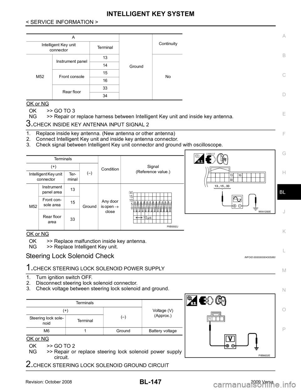
CHECK INSIDE KEY ANTENNA INPUT SIGNAL 2
1. Replace inside key antenna. (New antenna or other antenna)
2. Connect Intelligent Key unit and inside key antenna connector.
3. Check signal between Intelligent Key unit connector and ground with oscilloscope.
OK or NG OK >> Replace malfunction inside key antenna.
NG >> Replace Intelligent Key unit.
Steering Lock Solenoid Check INFOID:00000000043050601.
CHECK STEERING LOCK SOLENOID POWER SUPPLY
1. Turn ignition switch OFF.
2. Disconnect steering lock solenoid connector.
3. Check voltage between steering lock solenoid and ground.
OK or NG OK >> GO TO 2
NG >> Repair or replace steering lock solenoid power supply
circuit. 2.
CHECK STEERING LOCK SOLENOID GROUND CIRCUIT A
GroundContinuity
Intelligent Key unit
connector Terminal
M52 Instrument panel
13
No
14
Front console 15
16
Rear floor 33
34 Terminals
ConditionSignal
(Reference value.)
(+)
(–)
Intelligent Key unit
connector Ter-
minal
M52 Instrument
panel area 13
Ground Any door
is open →
close
Front con-
sole area 15
Rear floor area 33 WIIA1200E
PIIB5502J
Terminals Voltage (V)(Approx.)
(+)
(–)
Steering lock sole-
noid Terminal
M6 1 Ground Battery voltage PIIB6632E
Page 609 of 4331
BL-148< SERVICE INFORMATION >
INTELLIGENT KEY SYSTEM
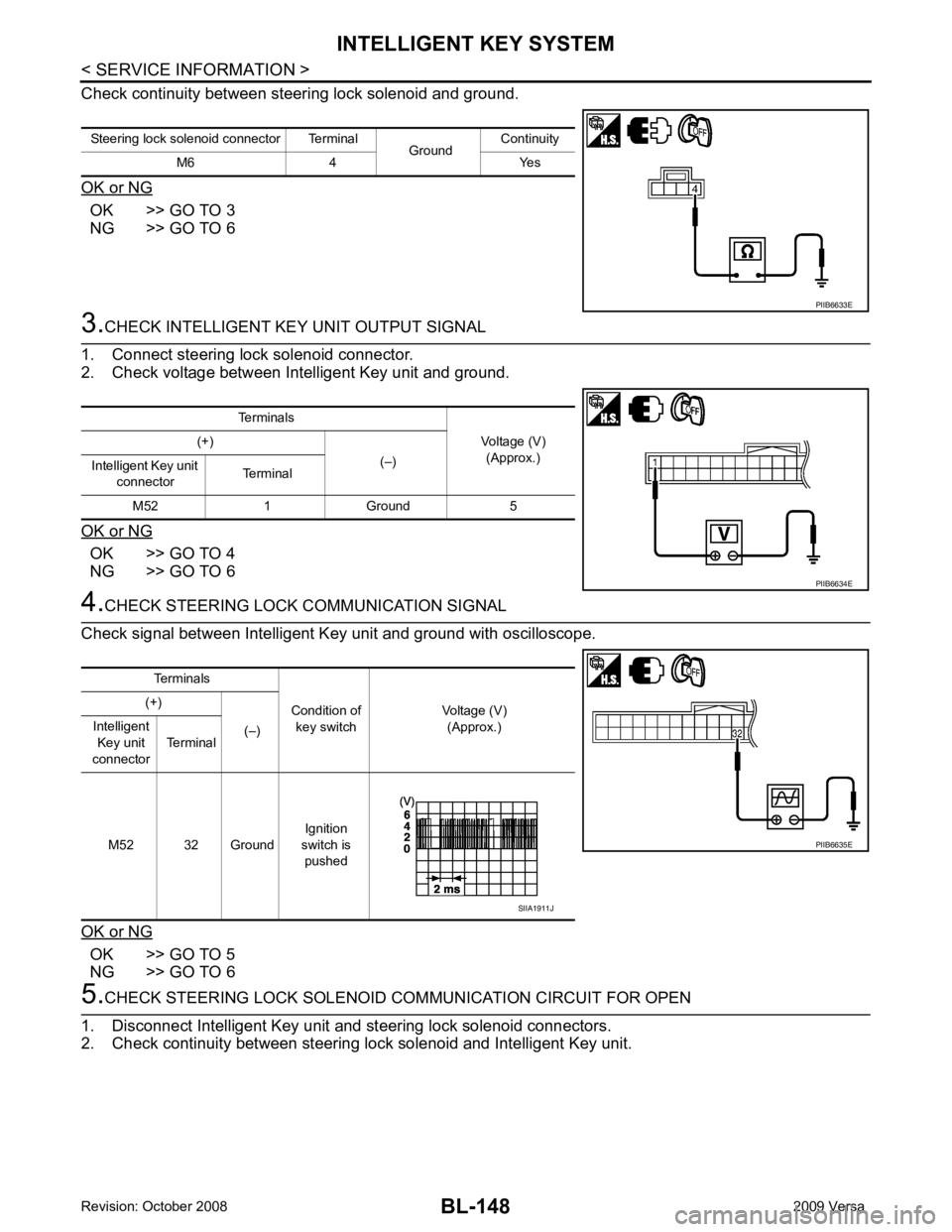
Check continuity between steering lock solenoid and ground.
OK or NG OK >> GO TO 3
NG >> GO TO 6 3.
CHECK INTELLIGENT KEY UNIT OUTPUT SIGNAL
1. Connect steering lock solenoid connector.
2. Check voltage between Intelligent Key unit and ground.
OK or NG OK >> GO TO 4
NG >> GO TO 6 4.
CHECK STEERING LOCK COMMUNICATION SIGNAL
Check signal between Intelligent Key unit and ground with oscilloscope.
OK or NG OK >> GO TO 5
NG >> GO TO 6 5.
CHECK STEERING LOCK SOLENOID COMMUNICA TION CIRCUIT FOR OPEN
1. Disconnect Intelligent Key unit and steering lock solenoid connectors.
2. Check continuity between steering lock solenoid and Intelligent Key unit. Steering lock solenoid connector Terminal
GroundContinuity
M6 4 Yes PIIB6633E
Terminals
Voltage (V)(Approx.)
(+)
(–)
Intelligent Key unit
connector Terminal
M52 1 Ground 5 PIIB6634E
Terminals
Condition of key switch Voltage (V)
(Approx.)
(+)
(–)
Intelligent
Key unit
connector Terminal
M52 32 Ground Ignition
switch is pushed PIIB6635E
SIIA1911J
Page 613 of 4331
BL-152< SERVICE INFORMATION >
INTELLIGENT KEY SYSTEM
Stop Lamp Switch Check (With M/T) INFOID:00000000043050641.
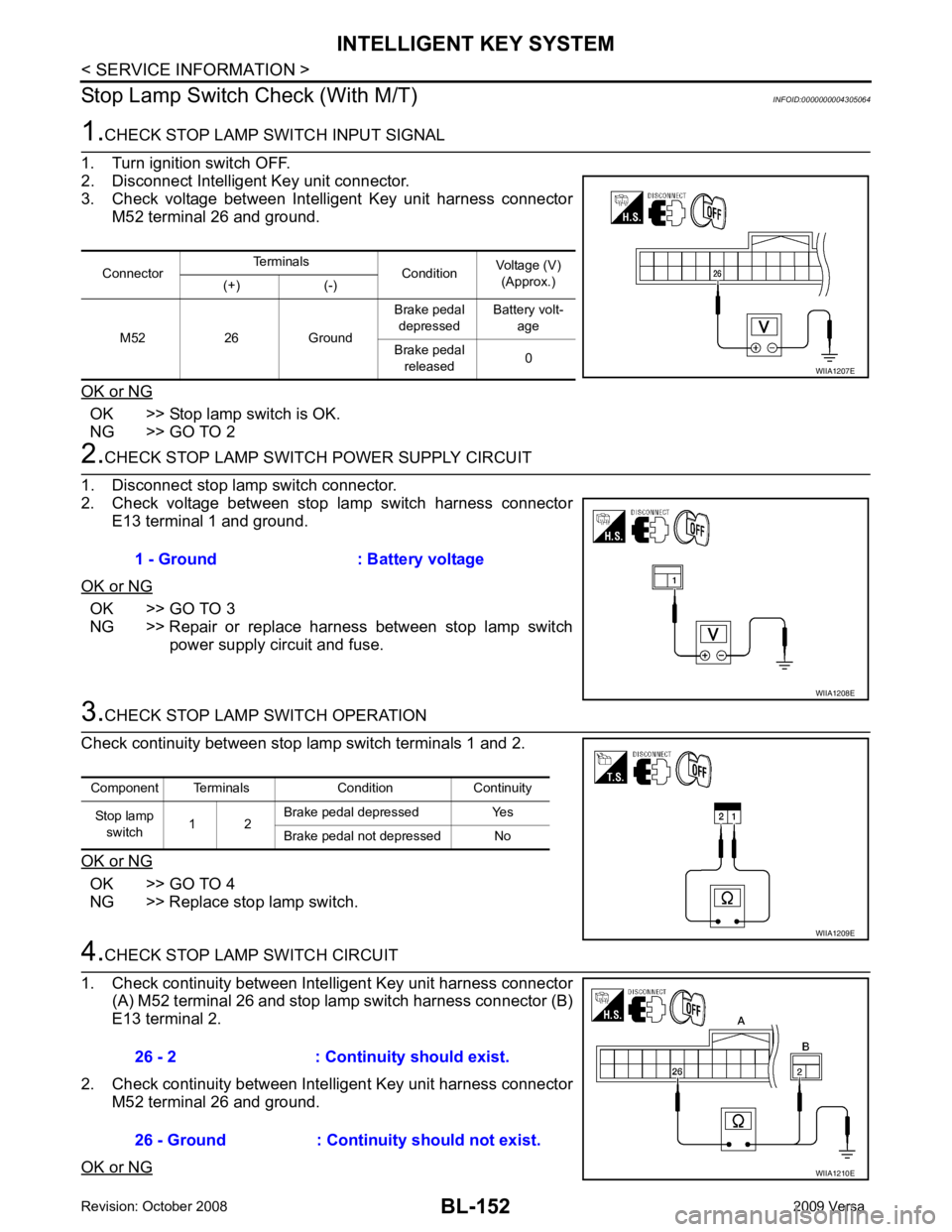
CHECK STOP LAMP SWITCH INPUT SIGNAL
1. Turn ignition switch OFF.
2. Disconnect Intelligent Key unit connector.
3. Check voltage between Intelligent Key unit harness connector M52 terminal 26 and ground.
OK or NG OK >> Stop lamp switch is OK.
NG >> GO TO 2 2.
CHECK STOP LAMP SWIT CH POWER SUPPLY CIRCUIT
1. Disconnect stop lamp switch connector.
2. Check voltage between stop lamp switch harness connector
E13 terminal 1 and ground.
OK or NG OK >> GO TO 3
NG >> Repair or replace harness between stop lamp switch power supply circuit and fuse. 3.
CHECK STOP LAMP SWITCH OPERATION
Check continuity between stop lamp switch terminals 1 and 2.
OK or NG OK >> GO TO 4
NG >> Replace stop lamp switch. 4.
CHECK STOP LAMP SWITCH CIRCUIT
1. Check continuity between Inte lligent Key unit harness connector
(A) M52 terminal 26 and stop lamp switch harness connector (B)
E13 terminal 2.
2. Check continuity between Inte lligent Key unit harness connector
M52 terminal 26 and ground.
OK or NG Connector
Terminals
ConditionVoltage (V)
(Approx.)
(+) (-)
M52 26 Ground Brake pedal
depressed Battery volt-
age
Brake pedal released 0 WIIA1207E
1 - Ground : Battery voltage
WIIA1208E
Component Terminals Condition Continuity
Stop lamp switch 1 2 Brake pedal depressed Yes
Brake pedal not depressed No WIIA1209E
26 - 2 : Continuity should exist.
26 - Ground : Continuity should not exist. WIIA1210E
Page 618 of 4331
INTELLIGENT KEY SYSTEM
BL-157
< SERVICE INFORMATION >
C
D E
F
G H
J
K L
M A
B BL
N
O P
Horn Function Check
INFOID:0000000004305072
First perform the “SELF-DIAG RESULTS” of “BCM” with CONSULT-III, then perform the trouble diag-
nosis of malfunction system indicated in “ SELF-DIAG RESULTS” of “BCM”. Refer to BCS-17, " CAN
Communication Inspection Using CONSULT-III (Self-Diagnosis) " .
1.
CHECK HORN OPERATION
Check if horn sounds with horn switch.
Does horn operate? Yes >> GO TO 2
No >> Check horn circuit. Refer to WW-38 .
2.
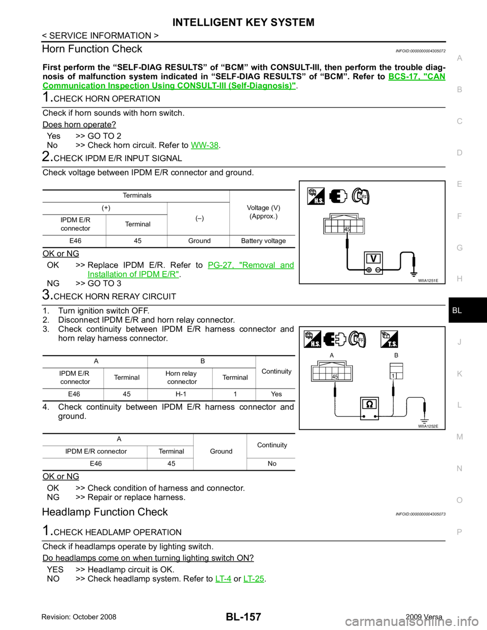
CHECK IPDM E/R INPUT SIGNAL
Check voltage between IPDM E/R connector and ground.
OK or NG OK >> Replace IPDM E/R. Refer to
PG-27, " Removal and
Installation of IPDM E/R " .
NG >> GO TO 3 3.
CHECK HORN RERAY CIRCUIT
1. Turn ignition switch OFF.
2. Disconnect IPDM E/R and horn relay connector.
3. Check continuity between IPDM E/R harness connector and horn relay harness connector.
4. Check continuity between IPDM E/R harness connector and ground.
OK or NG OK >> Check condition of harness and connector.
NG >> Repair or replace harness.
Headlamp Function Check INFOID:00000000043050731.
CHECK HEADLAMP OPERATION
Check if headlamps operate by lighting switch.
Do headlamps come on when turning lighting switch ON? YES >> Headlamp circuit is OK.
NO >> Check headlamp system. Refer to LT-4 or
LT-25 .
Terminals
Voltage (V)(Approx.)
(+)
(–)
IPDM E/R
connector Terminal
E46 45 Ground Ba ttery voltage WIIA1251E
A B
Continuity
IPDM E/R
connector Terminal
Horn relay
connector Terminal
E46 45 H-1 1 Yes
A GroundContinuity
IPDM E/R connector Terminal
E46 45 No WIIA1252E
Page 631 of 4331
BL-170< SERVICE INFORMATION >
REAR DOOR LOCK
5. Remove the door side grommet, and the outside handle escutcheon screw.
6. Pull the outside handle forward (1), while removing outside han- dle escutcheon (2).
7. Pull outside door handle forward (1), and slide it toward the rear of the vehicle to remove (2).
8. Remove the front and rear gaskets.
9. Remove the door lock assembly screws. PIIB5808E
PIIB5809E
PIIB5810E
PIIB6526E
: 5.8 N·m (0.6 kg-m, 51.4 in-lb)
PIIB6527E
Page 632 of 4331
REAR DOOR LOCK
BL-171
< SERVICE INFORMATION >
C
D E
F
G H
J
K L
M A
B BL
N
O P
10. Slide the outside handle bracket toward the rear of vehicle,
remove the outside handle bracket and the door lock assembly.
11. If equipped, disconnect the door lock assembly electrical connector.
12. Disconnect the outside handle cable from the outside handle bracket.
INSTALLATION Installation is in the reverse order of removal.
CAUTION:
• To install each rod, be sure to rotate the rod holder until a click is felt.
• When installing door lock assembly, be careful when rotating the outside handle cable as shown.
- Place the outside handle bracket cable on the inside of door
lock assembly before installing. PIIB6528E
PIIB5815E
PIIB6529E
Page 636 of 4331
BACK DOOR LOCK
BL-175
< SERVICE INFORMATION >
C
D E
F
G H
J
K L
M A
B BL
N
O P
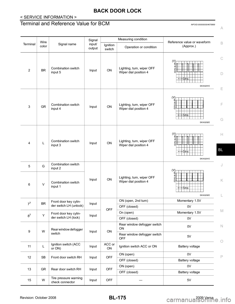
Terminal and Reference Value for BCM
INFOID:0000000004678868
Terminal Wire
color Signal name Signal
input/
output Measuring condition
Reference value or waveform
(Approx.)
Ignition
switch Operation or condition
2 BR Combination switch
input 5 Input ONLighting, turn, wiper OFF
Wiper dial position 4
3 GR Combination switch
input 4 Input ONLighting, turn, wiper OFF
Wiper dial position 4
4 L Combination switch
input 3 Input ONLighting, turn, wiper OFF
Wiper dial position 4
5 G Combination switch
input 2
Input ONLighting, turn, wiper OFF
Wiper dial position 4
6 V Combination switch
input 1
7 7
BRFront door key cylin-
der switch LH (unlock) Input
OFFON (open, 2nd turn) Momentary 1.5V
OFF (closed) 0V
8 7
YFront door key cylin-
der switch LH (lock) InputOn (open) Momentary 1.5V
OFF (closed) 0V
9 W Rear window defogger
switch Input ONRear window defogger switch
ON 0V
Rear window defogger switch
OFF 5V
11 L Ignition switch (ACC
or ON) InputACC or
ON Ignition switch ACC or ON Battery voltage
12 SB Front door switch RH Input OFF ON (open) 0V
OFF (closed) Battery voltage
13 GR Rear door switch RH Input OFF ON (open) 0V
OFF (closed) Battery voltage
15 W Tire pressure warning
check connector Input OFF — 5V SKIA5291E
SKIA5292E
SKIA5291E
SKIA5292E
Page 637 of 4331
BL-176< SERVICE INFORMATION >
BACK DOOR LOCK
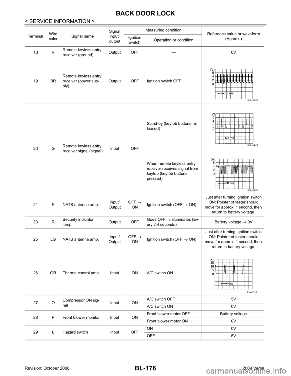
18 V Remote keyless entry
receiver (ground) Output OFF — 0V
19 BR Remote keyless entry
receiver (power sup-
ply) Output OFF Ignition switch OFF
20 G Remote keyless entry
receiver signal (signal) Input OFFStand-by (keyfob buttons re-
leased)
When remote keyless entry
receiver receives signal from
keyfob (keyfob buttons
pressed)
21 P NATS antenna amp. Input/
Output OFF
→
ON Ignition switch (OFF
→ ON) Just after turning ignition switch
ON: Pointer of tester should
move for approx. 1 second, then return to battery voltage.
23 R Security indicator
lamp Output OFFGoes OFF
→ illuminates (Ev-
ery 2.4 seconds) Battery voltage
→ 0V
25 LG NATS antenna amp. Input/
Output OFF
→
ON Ignition switch (OFF
→ ON) Just after turning ignition switch
ON: Pointer of tester should
move for approx. 1 second, then
return to battery voltage.
26 GR Thermo control amp. Input ON A/C switch ON
27 O Compressor ON sig-
nal Input ONA/C switch OFF 5V
A/C switch ON 0V
28 P Front blower monitor Input ON Front blower motor OFF Battery voltage
Front blower motor ON 0V
29 L Hazard switch Input OFF ON 0V
OFF 5V
Terminal
Wire
color Signal name Signal
input/
output Measuring condition
Reference value or waveform
(Approx.)
Ignition
switch Operation or condition LIIA1893E
LIIA1894E
LIIA1895E
ZJIA0719J