Page 3125 of 4331

Component " .
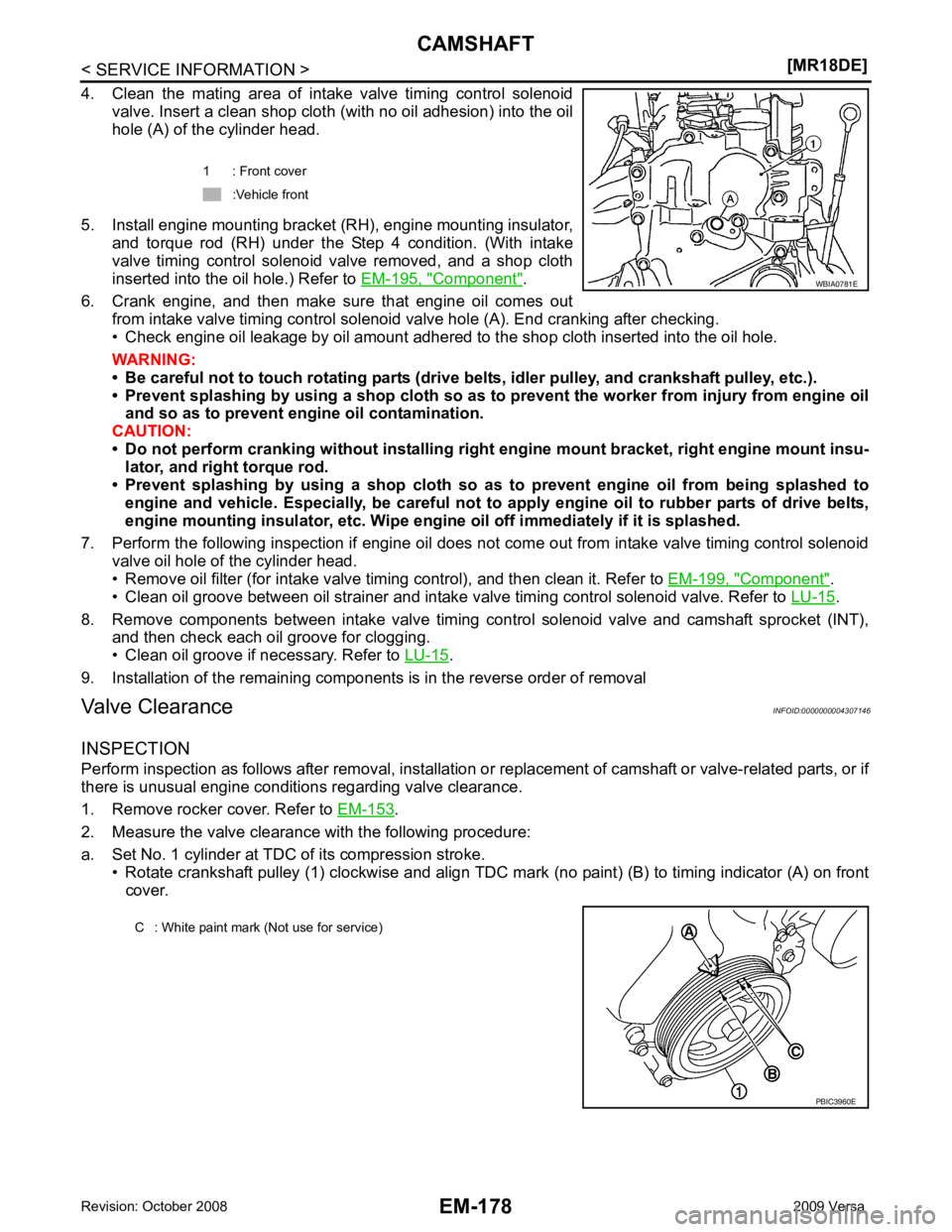
6. Crank engine, and then make sure that engine oil comes out from intake valve timing control solenoid valve hole (A). End cranking after checking.
• Check engine oil leakage by oil amount adhered to the shop cloth inserted into the oil hole.
WARNING:
• Be careful not to touch rotating parts (drive be lts, idler pulley, and crankshaft pulley, etc.).
• Prevent splashing by using a shop cloth so as to prevent the worker from injury from engine oil
and so as to prevent engi ne oil contamination.
CAUTION:
• Do not perform cranking without installing right engine mount bracket, right engine mount insu-
lator, and right torque rod.
• Prevent splashing by using a shop cloth so as to prevent engine oil from being splashed to
engine and vehicle. Especially, be careful not to apply engine oil to rubber parts of drive belts,
engine mounting insulator, etc. Wipe engi ne oil off immediately if it is splashed.
7. Perform the following inspection if engine oil does not come out from intake valve timing control solenoid valve oil hole of the cylinder head.
• Remove oil filter (for intake valve timing control), and then clean it. Refer to EM-199, " Component " .
• Clean oil groove between oil strainer and intake valve timing control solenoid valve. Refer to LU-15 .
8. Remove components between intake valve timing c ontrol solenoid valve and camshaft sprocket (INT),
and then check each oil groove for clogging.
• Clean oil groove if necessary. Refer to LU-15 .
9. Installation of the remaining components is in the reverse order of removal
Valve Clearance INFOID:0000000004307146
INSPECTION
Perform inspection as follows after removal, installation or replacement of camshaft or valve-related parts, or if
there is unusual engine conditions regarding valve clearance.
1. Remove rocker cover. Refer to EM-153 .
2. Measure the valve clearance with the following procedure:
a. Set No. 1 cylinder at TDC of its compression stroke. • Rotate crankshaft pulley (1) clockwise and align TDC mark (no paint) (B) to timing indicator (A) on front
cover. 1 : Front cover
:Vehicle front
Page 3133 of 4331
Trouble Diagnosis Introduction "
(Type 1) or
EC-1089, " Trouble Diagnosis Introduction " (Type 2).
Component INFOID:0000000004307151
Removal and Installation INFOID:0000000004307152
REMOVAL
WARNING:
• Put a “CAUTION: FLAMMABLE” sign in the workshop.
• Be sure to work in a well ventilate d area and furnish workshop with a CO
2 fire extinguisher.
• Do not smoke while servicing fuel system. Keep open flames and sparks away from the work area.
1. Release the fuel pressure. Refer to EC-574, " Fuel Pressure Check " (Type 1) or
EC-1086, " Fuel Pressure
Check " (Type 2).
2. Drain engine coolant and engine oil. Refer to CO-35 and
LU-16 .
CAUTION:
• Perform this step when the engine is cold.
• Never spill engine coolant an d engine oil on drive belt.
3. Remove front fender protector (RH). Refer to EI-24 .
1. Cylinder head assembly 2. Cylinder head bolt 3. Cylinder head gasket
A. Refer to EM-186
Page 3138 of 4331
![NISSAN LATIO 2009 Service Repair Manual CYLINDER HEAD
EM-191
< SERVICE INFORMATION >
[MR18DE] C
D E
F
G H
I
J
K L
M A EM
NP
O
Measure the diameter of valv
e stem with a micrometer (A).
Valve Guide Inner Diameter Measure the inner diameter o NISSAN LATIO 2009 Service Repair Manual CYLINDER HEAD
EM-191
< SERVICE INFORMATION >
[MR18DE] C
D E
F
G H
I
J
K L
M A EM
NP
O
Measure the diameter of valv
e stem with a micrometer (A).
Valve Guide Inner Diameter Measure the inner diameter o](/manual-img/5/57359/w960_57359-3137.png)
CYLINDER HEAD
EM-191
< SERVICE INFORMATION >
[MR18DE] C
D E
F
G H
I
J
K L
M A EM
NP
O
Measure the diameter of valv
e stem with a micrometer (A).
Valve Guide Inner Diameter Measure the inner diameter of valve guide with a bore gauge.
Valve Guide Clearance (Valve guide clearance) = (Valve guide inner diameter) – (Valve stem diameter).
• If it exceeds the limit, replace valve guide and/or valve.
VALVE GUIDE REPLACEMENT When valve guide is removed, replace with oversized [0.2 mm (0.008 in)] valve guide.
1. To remove valve guide, heat cylinder head to 110 ° to 130 °C
(230 ° to 266 °F) by soaking in heated oil (A).
2. Drive out valve guide using suitable tools. WARNING:
Cylinder head contai ns heat, when workin g, wear protective
equipment to avoid getting burned. Standard
Intake : 5.465 - 5.480 mm (0.2152 - 0.2157 in)
Exhaust : 5.455 - 5.470 mm (0.2148 - 0.2154 in) PBIC3213J
Standard
: 5.500 - 5.518 mm (0.2165 - 0.2172 in)
Valve guide clearance:
Standard Intake : 0.020 - 0.053 mm (0.0008 - 0.0021 in)
Exhaust : 0.030 - 0.063 mm (0.0012 - 0.0025 in)
Limit : 0.1 mm (0.004 in) PBIC3214J
SEM931C
Page 3139 of 4331
EM-192< SERVICE INFORMATION >
[MR18DE]
CYLINDER HEAD
3. Ream cylinder head valve guide hole using suitable tool (A).
4. Heat cylinder head to 110 ° to 130 °C (230 ° to 266 °F) by soaking
in heated oil (A).
5. Press valve guide (1) from camshaft side to dimensions as shown.
WARNING:
Cylinder head contains heat, when working, wear protective
equipment to avoid getting burned.
6. Apply reamer finish to valve guide using suitable tool (A).
VALVE SEAT CONTACT
• After confirming that the dimensions of valve guides and valves are within specifications, perform this proce-
dure.
• Apply prussian blue (or white lead) onto contacting surfac e of valve seat to check the condition of the valve
contact on the surface. Valve guide hole diameter (for service parts):
: 9.675 - 9.696 mm (0.3809 - 0.3817 in) PBIC3215J
PBIC3214J
2 : Cylinder head
Projection (H) : 13.35 - 13.65 mm (0.526 - 0.537 in) PBIC3217J
Standard
: 5.500 - 5.518 mm (0.2165 - 0.2172 in) PBIC3215J
Page 3140 of 4331
![NISSAN LATIO 2009 Service Repair Manual CYLINDER HEAD
EM-193
< SERVICE INFORMATION >
[MR18DE] C
D E
F
G H
I
J
K L
M A EM
NP
O
• Check if the contact area band is continuous all around the circum-
ference.
• If not, grind to adjust valve NISSAN LATIO 2009 Service Repair Manual CYLINDER HEAD
EM-193
< SERVICE INFORMATION >
[MR18DE] C
D E
F
G H
I
J
K L
M A EM
NP
O
• Check if the contact area band is continuous all around the circum-
ference.
• If not, grind to adjust valve](/manual-img/5/57359/w960_57359-3139.png)
CYLINDER HEAD
EM-193
< SERVICE INFORMATION >
[MR18DE] C
D E
F
G H
I
J
K L
M A EM
NP
O
• Check if the contact area band is continuous all around the circum-
ference.
• If not, grind to adjust valve fitti ng and check again. If the contacting
surface still has NG conditions even after the re-check, replace
valve seat.
VALVE SEAT REPLACEMENT When valve seat is removed, replace with oversized [0.5 mm (0.020 in)] valve seat.
1. Bore out old seat until it collapses. Boring shoul d not continue beyond the bottom face of the seat recess
in cylinder head. Set the machine depth stop to ensure this. Refer to EM-227, " Standard and Limit " .
2. Ream cylinder head (1) recess diameter for service valve seat.
• Be sure to ream in circles concentric to the valve guide center.This will enable valve seat to fit correctly.
3. Heat cylinder head to 110 ° to 130 °C (230 ° to 266 °F) by soaking
in heated oil (A).
4. Provide valve seats cooled well with dry ic e. Press-fit valve seat into cylinder head.
WARNING:
• Never touch cold valve seats directly.
• Cylinder head contains heat, wh en working, wear protective equipment to avoid getting burned.
5. Using valve seat cutter set or valve seat grinder, finish valve seat to the specified dimensions. For dimensions, refer to EM-227, " Standard and Limit " .
CAUTION:
When using valve seat cutter, firmly grip the cutter handle
with both hands. Then, press on the contacting surface all
around the circumference to cu t in a single drive. Improper
pressure on the cutter or cutting many different times may
result in staged valve seat.
6. Using compound, grind to adjust valve fitting.
7. Check again for normal contact. SBIA0322E
2 : Valve seat
Oversize [0.5 mm (0.020 in)] Intake : 35.200 - 35.227 mm (1.3858 - 1.3869 in)
Exhaust : 29.200 - 29.227 mm (1.1496 - 1.1507 in) PBIC3218J
PBIC3214J
SEM934C
Page 3142 of 4331
EM
NP
O
ENGINE ASSEMBLY
Component INFOID:0000000004307156
Removal and Installation INFOID:0000000004307157
WARNING:
• Situate the vehicle on a flat and solid surface.
• Place chocks at front and back of rear wheels.
• Attach proper slingers and bolts described in P ARTS CATALOG if engine slingers are not equipped.
CAUTION:
• Always be careful to work safely, avoid forceful or uninstructed operations.
• Do not start working until exhaust system and coolant are cool enough.
• If items or work required are not covered by th e engine section, follow the applicable procedures.
• Always use the support poin t specified for lifting.
1. Engine mounting Insulator (RH) 2. Engine mounting shim (RH) (if equipped) 3. Engine mounting bracket (RH)
4. Bracket 5. Rear torque rod 6. Engine through bolt
7. Engine mounting bracket (LH) 8. Engine mounting insulator (LH) 9. Torque rod (RH)
A. Front mark B. Silicone lubricant
Page 3150 of 4331

EM
NP
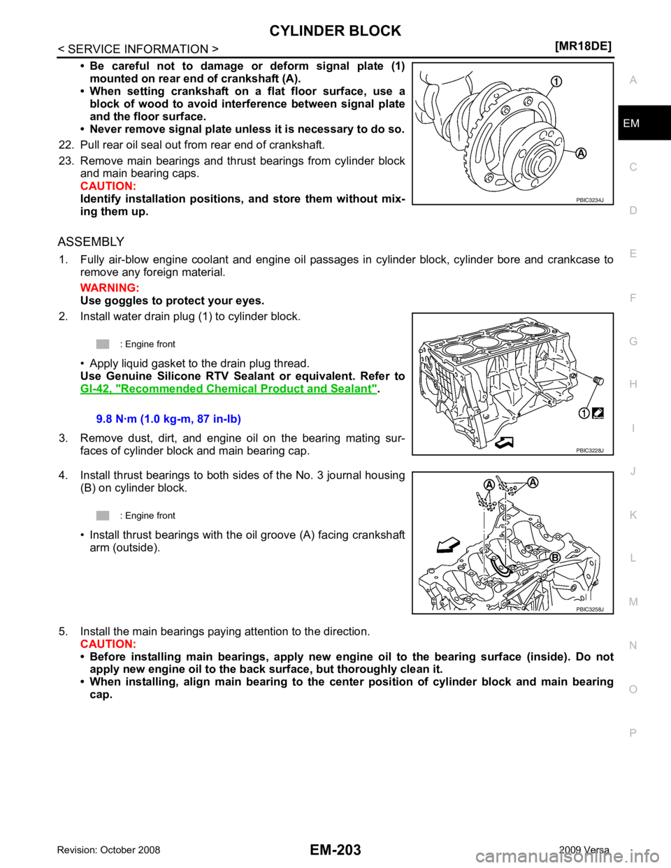
O
• Be careful not to damage or deform signal plate (1)
mounted on rear end of crankshaft (A).
• When setting crankshaft on a flat floor surface, use a
block of wood to avoid inte rference between signal plate
and the floor surface.
• Never remove signal plate unl ess it is necessary to do so.
22. Pull rear oil seal out from rear end of crankshaft.
23. Remove main bearings and thrust bearings from cylinder block and main bearing caps.
CAUTION:
Identify installation positions, and store them without mix-
ing them up.
ASSEMBLY 1. Fully air-blow engine coolant and engine oil passages in cylinder block, cylinder bore and crankcase to remove any foreign material.
WARNING:
Use goggles to protect your eyes.
2. Install water drain plug (1) to cylinder block.
• Apply liquid gasket to the drain plug thread.
Use Genuine Silicone RTV Seal ant or equivalent. Refer to
GI-42, " Recommended Chemical Product and Sealant " .
3. Remove dust, dirt, and engine oil on the bearing mating sur- faces of cylinder block and main bearing cap.
4. Install thrust bearings to both sides of the No. 3 journal housing (B) on cylinder block.
• Install thrust bearings with the oil groove (A) facing crankshaft arm (outside).
5. Install the main bearings paying attention to the direction. CAUTION:
• Before installing main bearings , apply new engine oil to the bearing surface (inside). Do not
apply new engine oil to the back surface, but thoroughly clean it.
• When installing, align main b earing to the center position of cylinder block and main bearing
cap.
Page 3189 of 4331
EX
NP
O
ON-VEHICLE REPAIR
EXHAUST SYSTEM
Component INFOID:0000000004784378
Removal and Installation INFOID:0000000004784393
WARNING:
• Perform the procedure with the exhaust system fu lly cooled down because the system will be hot
just after the engine is turned off.
• Be careful not to cut your hand on heat insulator edges.
CAUTION:
• Use genuine NISSAN exhaust system parts or equi valent, which are specially designed for heat
resistance, corrosion resistance and shape.
REMOVAL Remove exhaust system components using power tools.
• Remove heated oxygen sensor using Tool as needed.
CAUTION: 1. Main muffler 2. Mounting rubber 3. Ring gasket
4. Center muffler 5. Mounting rubber 6. Spring
7. Seal bearing 8. Heated oxygen sensor 2 9. Exhaust front tube
10. Seal bearing 11. Stud bolt 12. Spring
13. Ground cable