2009 NISSAN LATIO warning
[x] Cancel search: warningPage 2942 of 4331
HEADLINING
EI-51
< ON-VEHICLE REPAIR >
C
D E
F
G H
J
K L
M A
B EI
N
O P
Avoid headlining damage when
installing by inserting rear clips first during assembly.
Removal and Installation - Sedan INFOID:0000000004307237
REMOVAL 1. Disconnect the negative and positive battery term inals, then wait at least three minutes.
2. Remove front seat assembly RH/LH. Refer to SE-12, " Removal and Installation " .
3. Remove rear seat cushion and rear seatback. Refer to SE-16, " Removal and Installation " .
4. Remove front seat belt shoulder anchor RH/LH. Refer to SB-4, " Removal and Installation of Front Seat
Belt " .
5. Remove center console body assembly. Refer to IP-11 .
6. Remove front pillar garnish RH/LH. Refer to EI-40, " Removal and Installation " .
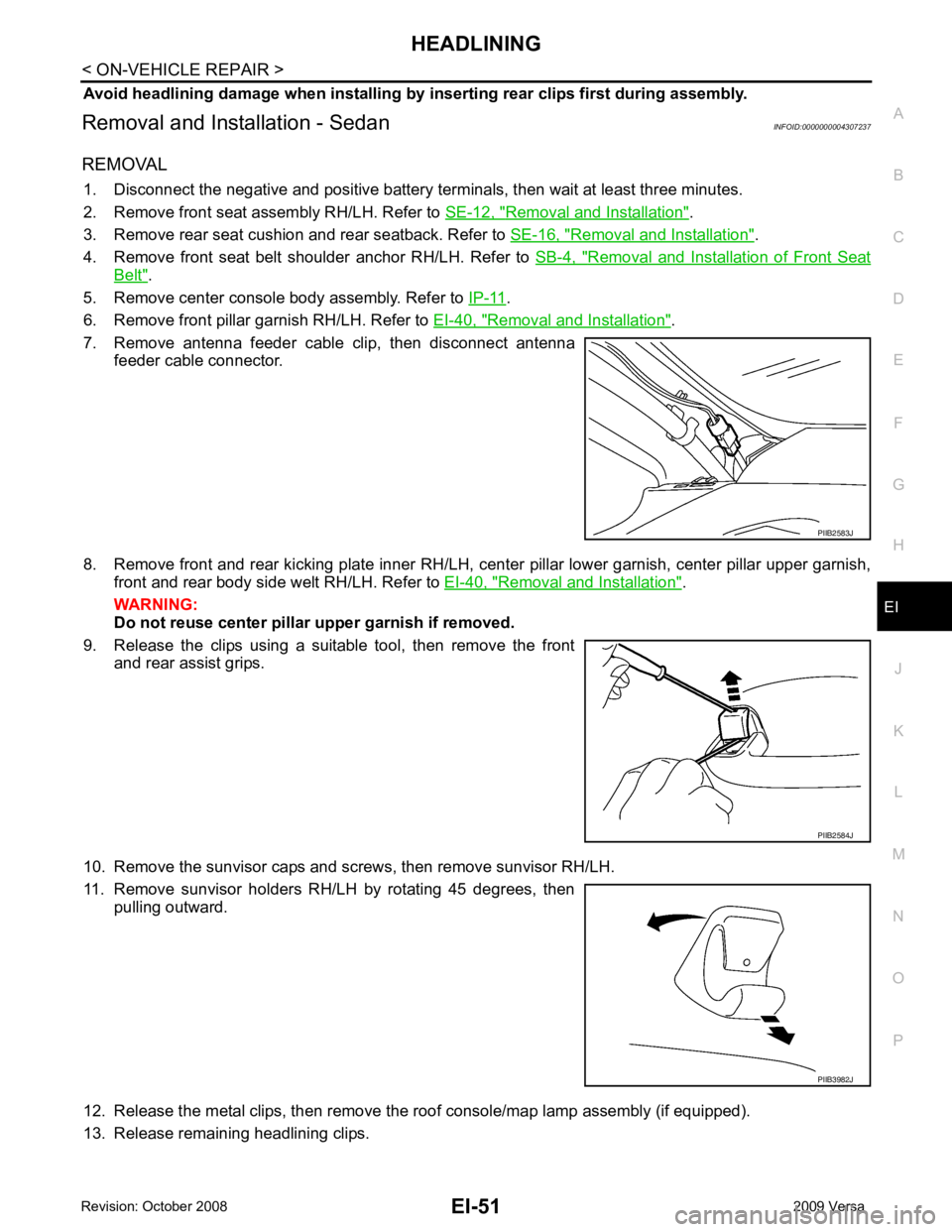
7. Remove antenna feeder cable clip, then disconnect antenna feeder cable connector.
8. Remove front and rear kicking plate inner RH/LH, cent er pillar lower garnish, center pillar upper garnish,
front and rear body side welt RH/LH. Refer to EI-40, " Removal and Installation " .
WARNING:
Do not reuse center pillar upper garnish if removed.
9. Release the clips using a suitable tool, then remove the front and rear assist grips.
10. Remove the sunvisor caps and screws, then remove sunvisor RH/LH.
11. Remove sunvisor holders RH/LH by rotating 45 degrees, then pulling outward.
12. Release the metal clips, then remove the roof console/map lamp assembly (if equipped).
13. Release remaining headlining clips. PIIB2583J
PIIB2584J
PIIB3982J
Page 2986 of 4331
EM
NP
O
OIL PAN (LOWER)
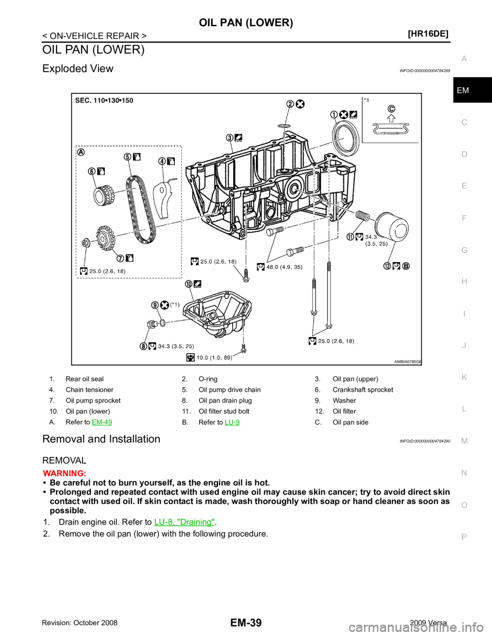
Exploded View INFOID:0000000004784289
Removal and Installation INFOID:0000000004784290
REMOVAL WARNING:
• Be careful not to burn yourself, as the engine oil is hot.
• Prolonged and repeated contact with used engine oil may cau se skin cancer; try to avoid direct skin
contact with used oil. If skin contact is made, w ash thoroughly with soap or hand cleaner as soon as
possible.
1. Drain engine oil. Refer to LU-8, " Draining " .
2. Remove the oil pan (lower) with the following procedure. 1. Rear oil seal 2. O-ring 3. Oil pan (upper)
4. Chain tensioner 5. Oil pump drive chain 6. Crankshaft sprocket
7. Oil pump sprocket 8. Oil pan drain plug 9. Washer
10. Oil pan (lower) 11. Oil filter stud bolt 12. Oil filter
A. Refer to EM-49 B. Refer to
LU-9 C. Oil pan side
Page 3021 of 4331
Fluids and Lubricants " .
• Use procedure below to check for fuel leakage.
- Turn ignition switch “ON” (with engine stopped). With fuel pressure applied to fuel piping, check for fuel leak-
age at connection points.
- Start engine. With engine speed increased, che ck again for fuel leakage at connection points.
• Run engine to check for unusual noise and vibration. NOTE:
If hydraulic pressure inside timing chain tensioner drops after removal/installation, slack in the guide may
generate a pounding noise during and just after engine start. However, this is normal. Noise will stop after
hydraulic pressure rises.
• Warm up engine thoroughly to make sure there is no leakage of fuel, or any oil/fluids including engine oil and
engine coolant.
• Bleed air from lines and hoses of applicable lines, such as in cooling system.
• After cooling down engine, again check oil/fluid levels including engine oil and engine coolant. Refill to the
specified level, if necessary.
Summary of the inspection items:
*: Transmission/transaxle/CVT fluid, power steering fluid, brake fluid, etc.
Inspection of Camshaft Sprocket (INT) Oil Groove
CAUTION:
• Perform this inspection only when DTC P0011 is de tected in self-diagnostic results of CONSULT-III
and it is directed according to inspect ion procedure of EC section. Refer to EC-133, " Diagnosis Pro-
cedure " .
• Check when engine is cold so as to pr event burns from the splashing engine oil.
1. Check engine oil level. Refer to LU-7, " Inspection " .
2. Perform the following procedure so as to prevent the engine from being unintentionally started while
checking.
a. Release the fuel pressure. Refer to EC-498, " Inspection " .
b. Remove intake manifold. Refer to EM-28, " Exploded View " .
c. Disconnect ignition coil and injector harness connectors. Refer to EM-46, " Exploded View " .
3. Remove intake valve timing control solenoid valve. Refer to EM-49, " Exploded View " .
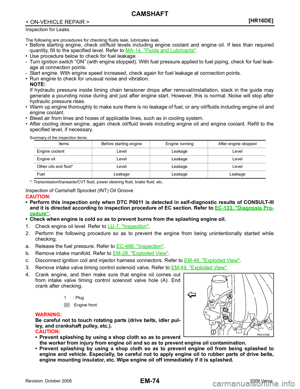
4. Crank engine, and then make sure that engine oil comes out from intake valve timing control solenoid valve hole (A). End
crank after checking.
WARNING:
Be careful not to touch rotating parts (drive belts, idler pul-
ley, and crankshaft pulley, etc.).
CAUTION:
• Prevent splashing by using a shop cloth so as to prevent
the worker from injury from engine oil an d so as to prevent engine oil contamination.
• Prevent splashing by using a shop cloth so as to prevent engine oil from being splashed to
engine and vehicle. Especially, be careful not to apply engine oil to rubber parts of drive belts,
engine mounting insulator, etc. Wipe engi ne oil off immediately if it is splashed.
Items Before starting engine Engine running After engine stopped
Engine coolant Level Leakage Level
Engine oil Level Leakage Level
Other oils and fluid* Level Leakage Level
Fuel Leakage Leakage Leakage 1 : Plug
:Engine front
Page 3026 of 4331
EM
NP
O
CYLINDER HEAD
Removal and Installation INFOID:0000000004784305
REMOVAL WARNING:
• Put a “CAUTION: FLAMMABLE” sign in the workshop.
• Be sure to work in a well ventila ted area and furnish workshop with a CO
2 fire extinguisher.
• Do not smoke while servicing fuel system. Keep open flames and sparks away from the work area.
1. Release fuel pressure. Refer to EC-498, " Inspection " .
2. Drain engine coolant and engine oil. Refer to CO-11, " Changing Engine Coolant " and
LU-8, " Draining " .
CAUTION:
• Perform this step when the engine is cold.
• Never spill engine coolant an d engine oil on drive belt.
3. Remove the following components and related parts. • Front fender protector (RH): Refer to EI-24, " Removal and Installation " .
• Generator: Refer to SC-25, " Removal and Installation " .
• Exhaust front tube: Refer to EX-5, " Component " .
• Exhaust manifold: Refer to EM-31, " Exploded View " .
• Intake manifold: Refer to EM-28, " Exploded View " .
• Fuel tube and fuel injector: Refer to EM-34, " Exploded View " .
• Water outlet: Refer to CO-24, " Removal and Installation " .
• Drive belt: Refer to EM-15, " Removal and Installation " .
• Front cover: Refer to EM-49, " Exploded View " .
• Camshaft: Refer to EM-58, " Exploded View " .
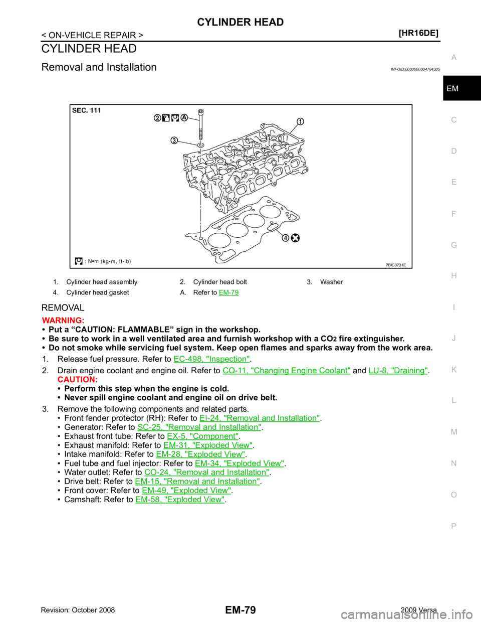
1. Cylinder head assembly 2. Cylinder head bolt 3. Washer
4. Cylinder head gasket A. Refer to EM-79
Page 3033 of 4331
![NISSAN LATIO 2009 Service Repair Manual EM-86< ON-VEHICLE REPAIR >
[HR16DE]
CYLINDER HEAD
c. Using suitable tool, press valve guide (1) from camshaft side to the dimensions as shown.
WARNING:
Cylinder head (2) contains h eat. Wear protectiv NISSAN LATIO 2009 Service Repair Manual EM-86< ON-VEHICLE REPAIR >
[HR16DE]
CYLINDER HEAD
c. Using suitable tool, press valve guide (1) from camshaft side to the dimensions as shown.
WARNING:
Cylinder head (2) contains h eat. Wear protectiv](/manual-img/5/57359/w960_57359-3032.png)
EM-86< ON-VEHICLE REPAIR >
[HR16DE]
CYLINDER HEAD
c. Using suitable tool, press valve guide (1) from camshaft side to the dimensions as shown.
WARNING:
Cylinder head (2) contains h eat. Wear protective equipment
to avoid getting burned.
d. Using suitable tool (A), apply reamer finish to valve guide.
2. Install the valve seat, if necessary. CAUTION:
Replace with oversize [0.5 mm (0.020 in)] valve seat.
a. Ream cylinder head recess diameter (a) for service valve seat.
• Be sure to ream in circles concentric to valve guide center.This will enable valve to fit correctly.
b. Heat cylinder head to 110 to 130 °C (230 to 266 °F) by soaking in
heated oil (A).
c. Provide valve seats cooled well with dry ice. Force fit valve seat into cylinder head. WARNING:
• Cylinder head contains heat. Wear prot ective equipment to avoid getting burned.
• Avoid directly touching cold valve seats. Projection “H”: Refer to
EM-119, " Cylinder Head " .
PBIC3217J
Standard: Refer to
EM-119, " Cylinder Head " .
PBIC3215J
For service parts: Oversize [0.5 mm (0.020 in)]
Refer to EM-119, " Cylinder Head " .
JPBIA0188ZZ
PBIC3214J
Page 3044 of 4331
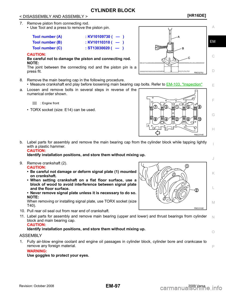
EM
NP
O
7. Remove piston from connecting rod.
• Use Tool and a press to remove the piston pin.
CAUTION:
Be careful not to damage the piston and connecting rod.
NOTE:
The joint between the connecting rod and the piston pin is a
press fit.
8. Remove the main bearing cap in the following procedure. • Measure crankshaft end play before loosening main bearing cap bolts. Refer to EM-103, " Inspection "
a. Loosen and remove bolts in several steps in reverse of the
numerical order shown.
• TORX socket (size: E14) can be used.
b. Label parts for assembly and remove the main beari ng cap from the cylinder block while tapping lightly
with a plastic hammer.
CAUTION:
Identify installation positions, and store th em without mixing up.
9. Remove crankshaft (2). CAUTION:
• Be careful not damage or deform signal plate (1) mounted on crankshaft.
• When setting crankshaft on a flat floor surface, use a
block of wood to avoid inte rference between signal plate
and the floor surface.
• Never remove signal plate unl ess it is necessary to do so.
NOTE:
When removing or installing signal plate, use TORX socket (size
T40).
10. Pull rear oil seal out from rear end of crankshaft.
11. Label parts for assembly and remove main bearing (upper and lower) and thrust bearings from cylinder block and main bearing cap.
CAUTION:
Identify installation positions, and store th em without mixing up.
ASSEMBLY 1. Fully air-blow engine coolant and engine oil passages in cylinder block, cylinder bore and crankcase to remove any foreign material.
WARNING:
Use goggles to protect your eyes. Tool number (A) : KV10109730 ( — )
Tool number (B) : KV10110310 ( — )
Tool number (C) : ST13030020 ( — )
Page 3084 of 4331
![NISSAN LATIO 2009 Service Repair Manual DRIVE BELTS
EM-137
< SERVICE INFORMATION >
[MR18DE] C
D E
F
G H
I
J
K L
M A EM
NP
O
1. Hold the hexagonal part (A) of drive belt auto-tensioner (1) with
a box wrench securely. Then move the wre NISSAN LATIO 2009 Service Repair Manual DRIVE BELTS
EM-137
< SERVICE INFORMATION >
[MR18DE] C
D E
F
G H
I
J
K L
M A EM
NP
O
1. Hold the hexagonal part (A) of drive belt auto-tensioner (1) with
a box wrench securely. Then move the wre](/manual-img/5/57359/w960_57359-3083.png)
DRIVE BELTS
EM-137
< SERVICE INFORMATION >
[MR18DE] C
D E
F
G H
I
J
K L
M A EM
NP
O
1. Hold the hexagonal part (A) of drive belt auto-tensioner (1) with
a box wrench securely. Then move the wrench handle in the
direction of arrow (loosening direction of tensioner).
WARNING:
Never place hand in a location where pinching may occur if
the holding tool accidentally comes off.
2. Insert a rod such as short-length screwdriver approximately 6 mm (0.24 in) in diameter into the hole (B) of retaining boss to fix
drive belt auto-tensioner.
3. Install drive belt. CAUTION:
• Confirm drive belt is completely set to pulleys.
• Check for engine oil, working fluid and engine coolant are not adhered to drive belt and each
pulley groove.
4. Release drive belt auto-tensioner, and apply tension to drive belt.
5. Turn crankshaft pulley clockwise several times to equalize tension between each pulley.
6. Confirm tension of drive belt at indicator (notch on fixed side) is within the possible use range. Refer to
EM-136, " Checking Drive Belts " .
Component INFOID:0000000004307127
Removal and Installation of Drive Belt Auto Tensioner INFOID:0000000004307128
REMOVAL 1. Remove drive belt. Refer to EM-136, " Removal and Installation " .
2. Release the fixed drive belt auto-tensioner pulley.
3. Loosen bolt and remove drive belt auto-tensioner. NOTE: PBIC3936E
1. Front cover 2. Drive belt auto–tensioner 3. Idler pulley (models without A/C)
4. Bracket (models without A/C) 5. Shaft (models without A/C) PBIC4698E
Page 3094 of 4331
EM
NP
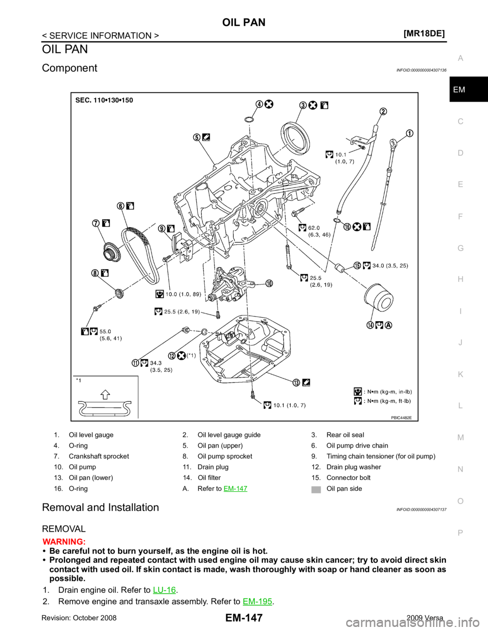
O
OIL PAN
Component INFOID:0000000004307136
Removal and Installation INFOID:0000000004307137
REMOVAL WARNING:
• Be careful not to burn yourself, as the engine oil is hot.
• Prolonged and repeated contact with used engine oil may cau se skin cancer; try to avoid direct skin
contact with used oil. If skin contact is made, w ash thoroughly with soap or hand cleaner as soon as
possible.
1. Drain engine oil. Refer to LU-16 .
2. Remove engine and transaxle assembly. Refer to EM-195 .
1. Oil level gauge 2. Oil level gauge guide 3. Rear oil seal
4. O-ring 5. Oil pan (upper) 6. Oil pump drive chain
7. Crankshaft sprocket 8. Oil pump sprocket 9. Timing chain tensioner (for oil pump)
10. Oil pump 11. Drain plug 12. Drain plug washer
13. Oil pan (lower) 14. Oil filter 15. Connector bolt
16. O-ring A. Refer to EM-147 Oil pan side