2009 NISSAN LATIO warning
[x] Cancel search: warningPage 3315 of 4331
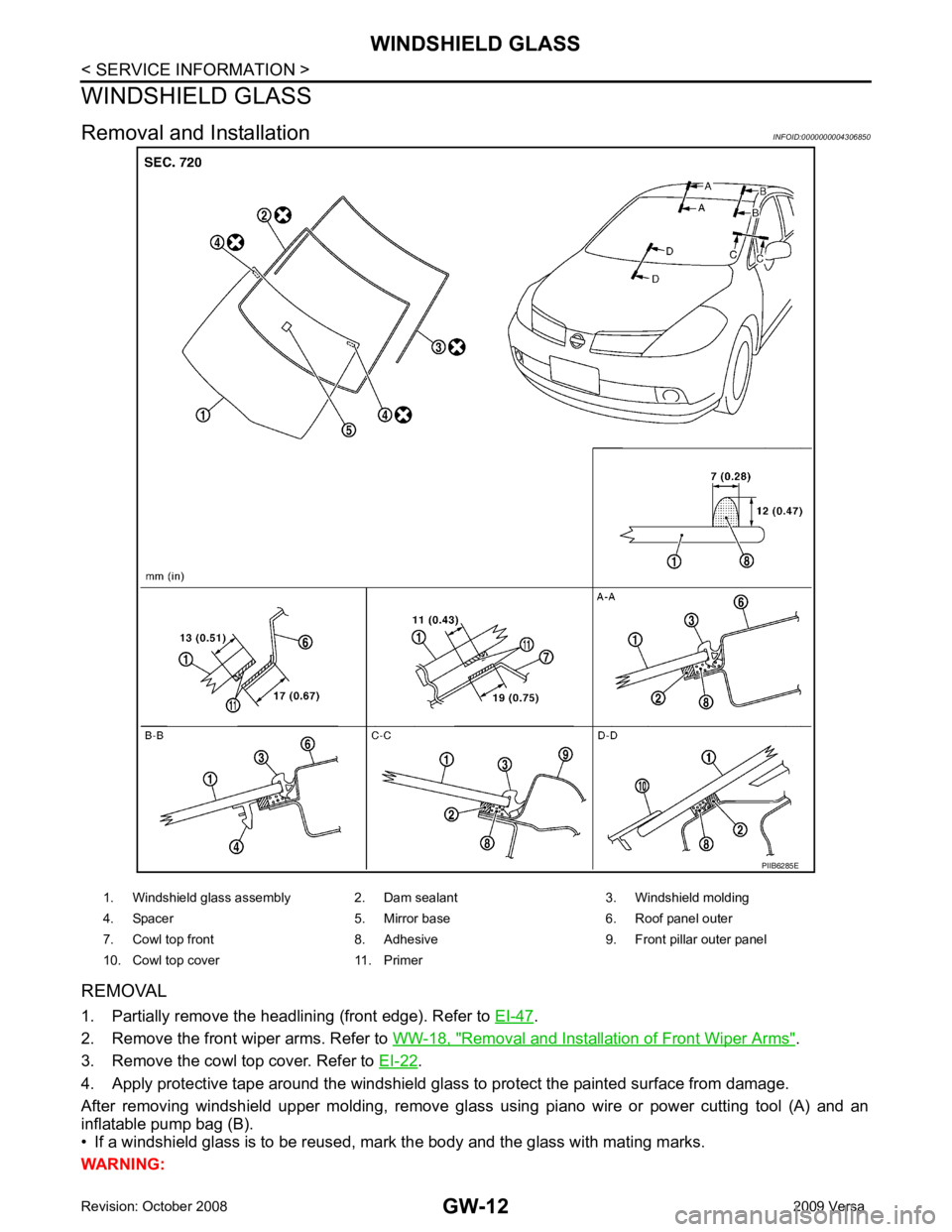
.
2. Remove the front wiper arms. Refer to WW-18, " Removal and Installation of Front Wiper Arms " .
3. Remove the cowl top cover. Refer to EI-22 .
4. Apply protective tape around the windshield glas s to protect the painted surface from damage.
After removing windshield upper molding, remove glass using piano wire or power cutting tool (A) and an
inflatable pump bag (B).
• If a windshield glass is to be reused, mark the body and the glass with mating marks.
WARNING:
Page 3316 of 4331
GW
N
O P
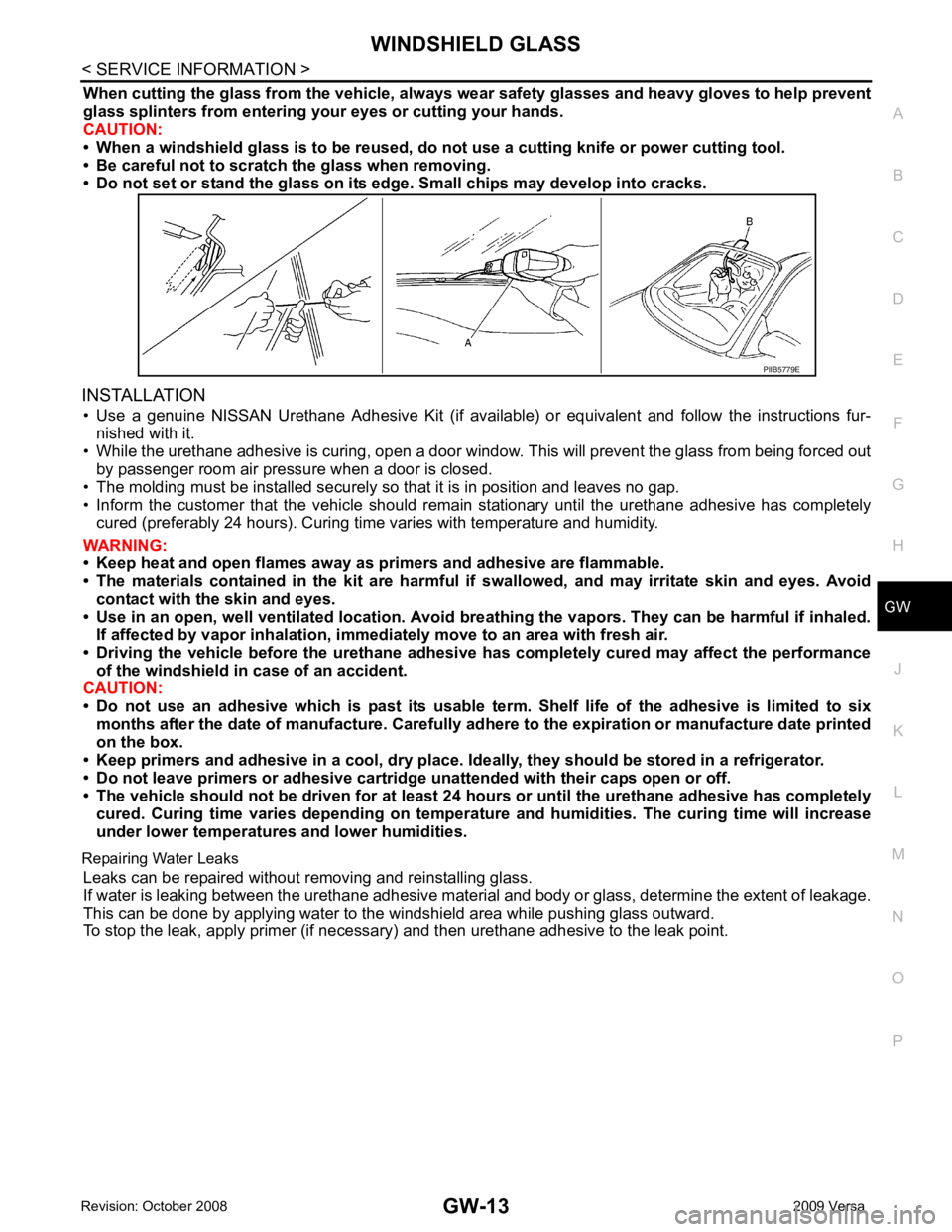
When cutting the glass from the vehicle, always
wear safety glasses and heavy gloves to help prevent
glass splinters from entering your eyes or cutting your hands.
CAUTION:
• When a windshield glass is to be reused, do no t use a cutting knife or power cutting tool.
• Be careful not to scratch the glass when removing.
• Do not set or stand the glass on its ed ge. Small chips may develop into cracks.
INSTALLATION • Use a genuine NISSAN Urethane Adhesive Kit (if availabl e) or equivalent and follow the instructions fur-
nished with it.
• While the urethane adhesive is curing, open a door window . This will prevent the glass from being forced out
by passenger room air pressure when a door is closed.
• The molding must be installed securely so that it is in position and leaves no gap.
• Inform the customer that the vehicle should rema in stationary until the urethane adhesive has completely
cured (preferably 24 hours). Curing time varies with temperature and humidity.
WARNING:
• Keep heat and open flames away as primers and adhesive are flammable.
• The materials contained in the kit are harmful if swallowed, and may irritate skin and eyes. Avoid
contact with the skin and eyes.
• Use in an open, well ventilated lo cation. Avoid breathing the vapors. They can be harmful if inhaled.
If affected by vapor inhalation, imme diately move to an area with fresh air.
• Driving the vehicle before the urethane adhesive has completely cured may affect the performance
of the windshield in case of an accident.
CAUTION:
• Do not use an adhesive which is past its usable te rm. Shelf life of the adhesive is limited to six
months after the date of manufacture. Carefully ad here to the expiration or manufacture date printed
on the box.
• Keep primers and adhesive in a cool, dry place. Id eally, they should be stored in a refrigerator.
• Do not leave primers or adhesive cartridge unattended with their caps open or off.
• The vehicle should not be driven for at least 24 hours or until the urethane adhesive has completely
cured. Curing time varies depend ing on temperature and humidities. The curing time will increase
under lower temperatures and lower humidities.
Repairing Water Leaks Leaks can be repaired without removing and reinstalling glass.
If water is leaking between the urethane adhesive material and body or glass, determine the extent of leakage.
This can be done by applying water to the windshield area while pushing glass outward.
To stop the leak, apply primer (if necessary ) and then urethane adhesive to the leak point.
Page 3317 of 4331
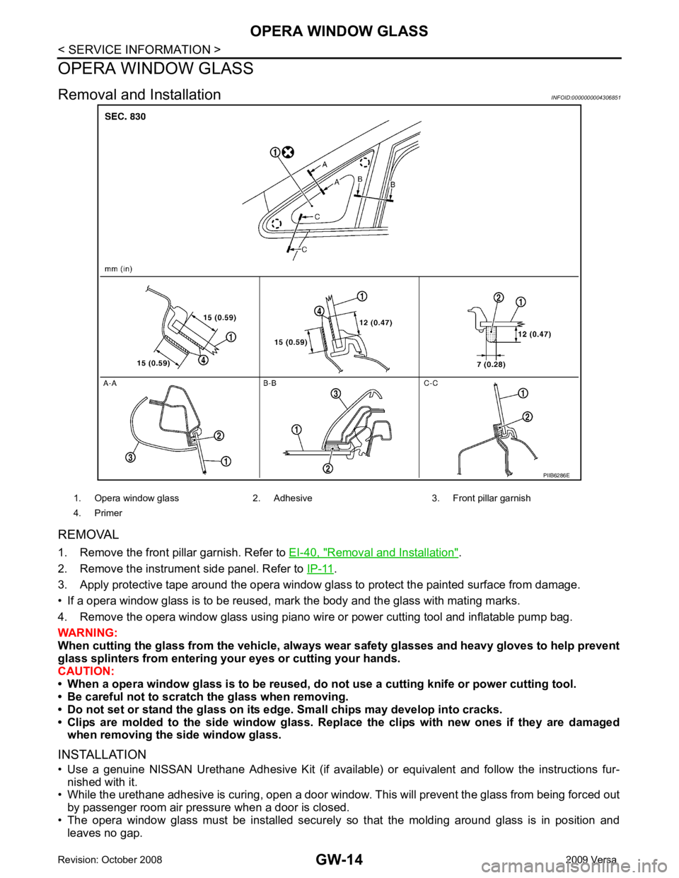
Removal and Installation " .
2. Remove the instrument side panel. Refer to IP-11 .
3. Apply protective tape around the opera window glas s to protect the painted surface from damage.
• If a opera window glass is to be reused, mark the body and the glass with mating marks.
4. Remove the opera window glass using piano wire or power cutting tool and inflatable pump bag.
WARNING:
When cutting the glass from the vehicle, always wear safety glasses and heavy gloves to help prevent
glass splinters from entering your eyes or cutting your hands.
CAUTION:
• When a opera window glass is to be reused, do not use a cutting knife or power cutting tool.
• Be careful not to scratch the glass when removing.
• Do not set or stand the glass on its edge. Small chips may develop into cracks.
• Clips are molded to the side window glass. Re place the clips with new ones if they are damaged
when removing the side window glass.
INSTALLATION
• Use a genuine NISSAN Urethane Adhesive Kit (if available) or equivalent and follow the instructions fur- nished with it.
• While the urethane adhesive is curing, open a door window . This will prevent the glass from being forced out
by passenger room air pressure when a door is closed.
• The opera window glass must be installed securely so that the molding around glass is in position and
leaves no gap.
Page 3318 of 4331

GW
N
O P
• Inform the customer that the vehicle should rema
in stationary until the urethane adhesive has completely
cured (preferably 24 hours). Curing time varies with temperature and humidity.
WARNING:
• Keep heat and open flames away as primers and adhesive are flammable.
• The materials contained in the kit are harmful if swallowed, and may irritate skin and eyes. Avoid
contact with the skin and eyes.
• Use in an open, well ventilated lo cation. Avoid breathing the vapors. They can be harmful if inhaled.
If affected by vapor inhalation, imme diately move to an area with fresh air.
• Driving the vehicle before the urethane adhesive has completely cured may affect the performance
of the side window in case of an accident.
CAUTION:
• Do not use an adhesive which is past its usable te rm. Shelf life of the adhesive is limited to six
months after the date of manufacture. Carefully ad here to the expiration or manufacture date printed
on the box.
• Keep primers and adhesive in a cool, dry place. Id eally, they should be stored in a refrigerator.
• Do not leave primers or adhesive cartridge unattended with their caps open or off.
• The vehicle should not be driven for at least 24 hours or until the urethane adhesive has completely
cured. Curing time varies depend ing on temperature and humidities. The curing time will increase
under lower temperature and lower humidity.
Repairing Water Leaks Leaks can be repaired without removing and reinstalling glass.
If water is leaking between the urethane adhesive material and body or glass, determine the extent of leakage.
This can be done by applying water to the side window area while pushing glass outward.
To stop the leak, apply primer (if necessary ) and then urethane adhesive to the leak point.
Page 3320 of 4331
GW
N
O P
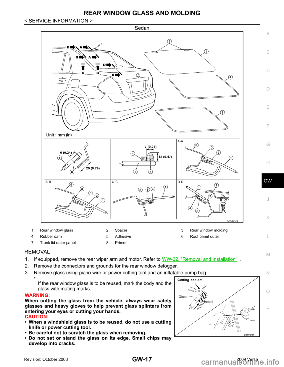
Sedan
REMOVAL 1. If equipped, remove the rear wiper arm and motor. Refer to WW-32, " Removal and Installation " .
2. Remove the connectors and grounds for the rear window defogger.
3. Remove glass using piano wire or power cutting tool and an inflatable pump bag. •
If the rear window glass is to be reused, mark the body and the
glass with mating marks.
WARNING:
When cutting the glass from th e vehicle, always wear safety
glasses and heavy gloves to help prevent glass splinters from
entering your eyes or cutting your hands.
CAUTION:
• When a windshield glass is to be reused, do not use a cutting knife or power cutting tool.
• Be careful not to scratch the glass when removing.
• Do not set or stand the glass on its edge. Small chips may develop into cracks.
Page 3418 of 4331
![NISSAN LATIO 2009 Service Repair Manual PRECAUTIONS
LAN-23
< PRECAUTION >
[CAN] C
D E
F
G H
I
J
L
M A
B LAN
N
O P
PRECAUTION
PRECAUTIONS
Precaution for Supplemental Restraint System (SRS) "AIR BAG" and "SEAT BELT
PRE-TENSIONER" INFOID:000 NISSAN LATIO 2009 Service Repair Manual PRECAUTIONS
LAN-23
< PRECAUTION >
[CAN] C
D E
F
G H
I
J
L
M A
B LAN
N
O P
PRECAUTION
PRECAUTIONS
Precaution for Supplemental Restraint System (SRS) "AIR BAG" and "SEAT BELT
PRE-TENSIONER" INFOID:000](/manual-img/5/57359/w960_57359-3417.png)
PRECAUTIONS
LAN-23
< PRECAUTION >
[CAN] C
D E
F
G H
I
J
L
M A
B LAN
N
O P
PRECAUTION
PRECAUTIONS
Precaution for Supplemental Restraint System (SRS) "AIR BAG" and "SEAT BELT
PRE-TENSIONER" INFOID:0000000004498345
The Supplemental Restraint System such as “A IR BAG” and “SEAT BELT PRE-TENSIONER”, used along
with a front seat belt, helps to reduce the risk or severi ty of injury to the driver and front passenger for certain
types of collision. This system includes seat belt switch inputs and dual stage front air bag modules. The SRS
system uses the seat belt switches to determine the front air bag deployment, and may only deploy one front
air bag, depending on the severity of a collision and w hether the front occupants are belted or unbelted.
Information necessary to service the system safely is included in the “SRS AIRBAG” and “SEAT BELT” of this
Service Manual.
WARNING:
• To avoid rendering the SRS inoper ative, which could increase the risk of personal injury or death in
the event of a collision which would result in air bag inflation, all maintenance must be performed by
an authorized NISSAN/INFINITI dealer.
• Improper maintenance, including in correct removal and installation of the SRS, can lead to personal
injury caused by unintentional act ivation of the system. For removal of Spiral Cable and Air Bag
Module, see the “SRS AIRBAG”.
• Never use electrical test equipment on any circuit re lated to the SRS unless instructed to in this Ser-
vice Manual. SRS wiring harnesses can be identifi ed by yellow and/or orange harnesses or harness
connectors.
PRECAUTIONS WHEN USING POWER TOOLS (AIR OR ELECTRIC) AND HAMMERS WARNING:
• When working near the Airbag Diagnosis Sensor Un it or other Airbag System sensors with the igni-
tion ON or engine running, DO NOT use air or el ectric power tools or strike near the sensor(s) with a
hammer. Heavy vibration could activate the sensor( s) and deploy the air bag(s), possibly causing
serious injury.
• When using air or electric power tools or hammers , always switch the ignition OFF, disconnect the
battery, and wait at least 3 minutes before performing any service.
Precautions for Trouble Diagnosis INFOID:0000000004306699
CAUTION:
• Never apply 7.0 V or more to the measurement terminal.
• Use a tester with open terminal voltage of 7.0 V or less.
• Turn the ignition switch OFF and disconnect th e battery cable from the negative terminal when
checking the harness.
Precautions for Harness Repair INFOID:0000000004306700
• Solder the repaired area and wrap tape around the soldered area. NOTE:
A fray of twisted lines must be within 110 mm (4.33 in). SKIB8766E
Page 3422 of 4331

LAN
N
O P
Engine status signal T R
Fuel consumption monitor signal T R
Malfunction indicator lamp signal T R
Wide open throttle position signal T R R
A/C switch signal R T
Blower fan motor switch signal R T
Buzzer output signal T R
T R
Day time running light request signal *3
T R
Door lock/unlock status signal T R
Door switch signal T R R R
Front wiper request signal T R
High beam request signal T R R
Horn chirp signal T R
Ignition switch signal T R
Low beam request signal T R
Position lights request signal T R R
Rear window defogger switch signal T R
Sleep/wake up signal R T
T R R R
Theft warning horn request signal T R
Tire pressure signal *4
T R
Trunk open/close status signal T R
Turn indicator signal T R
EPS operation signal R T
EPS warning lamp signal T R
Door lock/unlock/trunk open request signal R T
Hazard request signal R T
Ignition knob switch signal R T
KEY warning lamp signal T R
LOCK warning lamp signal T R
Panic alarm request signal R T
Fuel level sensor signal R T
Overdrive control switch signal T R R
P/N range signal T R
Stop lamp switch signal T R R
Vehicle speed signal R R R R T
R R R T R
R*5
T*5
ABS warning lamp signal R T
Brake warning lamp signal R T
A/T check indicator signal R T Signal name/Connecting unitECM
BCM EPS
I-KEY
M&AABS
TCM *1
TCM *2
IPDM-E
Page 3609 of 4331
LT
N
O P
SERVICE INFORMATION
PRECAUTIONS
Precaution for Supplemental Restraint System (SRS) "AIR BAG" and "SEAT BELT
PRE-TENSIONER" INFOID:0000000004306519
The Supplemental Restraint System such as “A IR BAG” and “SEAT BELT PRE-TENSIONER”, used along
with a front seat belt, helps to reduce the risk or severi ty of injury to the driver and front passenger for certain
types of collision. This system includes seat belt switch inputs and dual stage front air bag modules. The SRS
system uses the seat belt switches to determine the front air bag deployment, and may only deploy one front
air bag, depending on the severity of a collision and w hether the front occupants are belted or unbelted.
Information necessary to service the system safely is included in the SRS and SB section of this Service Man-
ual.
WARNING:
• To avoid rendering the SRS inoper ative, which could increase the risk of personal injury or death in
the event of a collision which would result in air bag inflation, all maintenance must be performed by
an authorized NISSAN/INFINITI dealer.
• Improper maintenance, including in correct removal and installation of the SRS, can lead to personal
injury caused by unintentional act ivation of the system. For removal of Spiral Cable and Air Bag
Module, see the SRS section.
• Do not use electrical test equipm ent on any circuit related to the SRS unless instructed to in this
Service Manual. SRS wiring harnesses can be identi fied by yellow and/or orange harnesses or har-
ness connectors.
Precaution Necessary for Steering Wh eel Rotation After Battery Disconnect
INFOID:0000000004683900
NOTE:
• This Procedure is applied only to models with Inte lligent Key system and NATS (NISSAN ANTI-THEFT SYS-
TEM).
• Remove and install all control units after disconnecti ng both battery cables with the ignition knob in the
″ LOCK ″ position.
• Always use CONSULT-III to perform self-diagnosis as a part of each function inspection after finishing work.
If DTC is detected, perform trouble diagnosis according to self-diagnostic results.
For models equipped with the Intelligent Key system and NATS , an electrically controlled steering lock mech-
anism is adopted on the key cylinder.
For this reason, if the battery is disconnected or if the battery is discharged, the steering wheel will lock and
steering wheel rotation will become impossible.
If steering wheel rotation is required when battery pow er is interrupted, follow the procedure below before
starting the repair operation.
OPERATION PROCEDURE 1. Connect both battery cables. NOTE:
Supply power using jumper cables if battery is discharged.
2. Use the Intelligent Key or mechanical key to turn the ignition switch to the ″ACC ″ position. At this time, the
steering lock will be released.
3. Disconnect both battery cables. The steering lock will remain released and the steering wheel can be
rotated.
4. Perform the necessary repair operation.
5. When the repair work is completed, return the ignition switch to the ″LOCK ″ position before connecting
the battery cables. (At this time, the steering lock mechanism will engage.)
6. Perform a self-diagnosis check of al l control units using CONSULT-III.