2009 NISSAN LATIO warning
[x] Cancel search: warningPage 3889 of 4331
MTC-4< SERVICE INFORMATION >
PRECAUTIONS
5. When the repair work is completed, return the ignition switch to the ″LOCK ″ position before connecting
the battery cables. (At this time, the steering lock mechanism will engage.)
6. Perform a self-diagnosis check of a ll control units using CONSULT-III.
Precaution for Procedure without Cowl Top Cover INFOID:0000000004307042
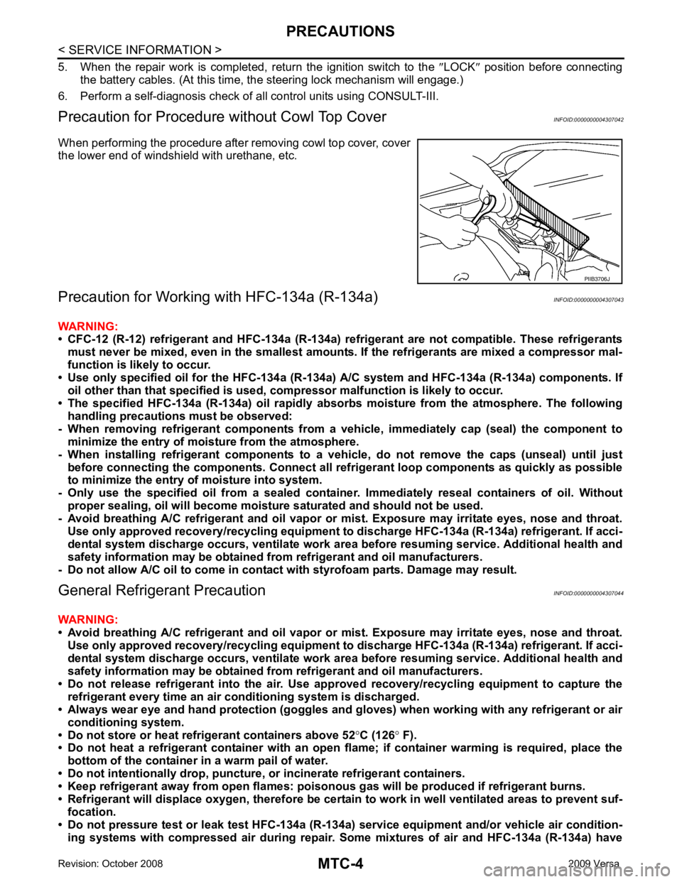
When performing the procedure after removing cowl top cover, cover
the lower end of windshield with urethane, etc.
Precaution for Working with HFC-134a (R-134a) INFOID:0000000004307043
WARNING:
• CFC-12 (R-12) refrigerant and HFC-134a (R-134a) re frigerant are not compatible. These refrigerants
must never be mixed, even in the smallest amounts. If the refrigerants are mixed a compressor mal-
function is likely to occur.
• Use only specified oil for the HFC-134a (R-134a) A/C system and HFC-134a (R-134a) components. If
oil other than that specifi ed is used, compressor malf unction is likely to occur.
• The specified HFC-134a (R-134a) oi l rapidly absorbs moisture from the atmosphere. The following
handling precautions must be observed:
- When removing refrigerant components from a vehicle, immediately cap (seal) the component to
minimize the entry of moisture from the atmosphere.
- When installing refrigerant co mponents to a vehicle, do not remove the caps (unseal) until just
before connecting the components . Connect all refrigerant loop components as quickly as possible
to minimize the entry of moisture into system.
- Only use the specified oil from a sealed container. Immediately reseal containers of oil. Without
proper sealing, oil will become moisture saturat ed and should not be used.
- Avoid breathing A/C refrigerant and oil vapor or mist. Exposure may irritate eyes, nose and throat.
Use only approved recovery/recycling equipment to discharge HFC-134a (R-134a) refrigerant. If acci-
dental system discharge occurs, ventilate work area before resuming service. Additional health and
safety information may be obtained fr om refrigerant and oil manufacturers.
- Do not allow A/C oil to come in contact with styrofoam parts. Damage may result.
General Refrigerant Precaution INFOID:0000000004307044
WARNING:
• Avoid breathing A/C refrigerant and oil vapor or mist. Exposure may irritate eyes, nose and throat.
Use only approved recovery/recycling equipment to discharge HFC-134a (R-134a) refrigerant. If acci-
dental system discharge occurs, ventilate work area before resuming service. Additional health and
safety information may be obtained fr om refrigerant and oil manufacturers.
• Do not release refrigerant into th e air. Use approved recovery/recycling equipment to capture the
refrigerant every time an air conditioning system is discharged.
• Always wear eye and hand protection (goggles and gloves) when working with any refrigerant or air
conditioning system.
• Do not store or heat refrigerant containers above 52 °C (126 ° F).
• Do not heat a refrigerant container with an open flame; if container warming is required, place the
bottom of the container in a warm pail of water.
• Do not intentionally drop, puncture, or incinerate refrigerant containers.
• Keep refrigerant away from open flames: poisonou s gas will be produced if refrigerant burns.
• Refrigerant will displace oxygen, therefore be certa in to work in well ventilated areas to prevent suf-
focation.
• Do not pressure test or leak test HFC-134a (R-134a) service equipment and/or vehicle air condition-
ing systems with compressed air during repair. Some mixtures of air and HFC-134a (R-134a) have PIIB3706J
Page 4002 of 4331
PG
N
O P
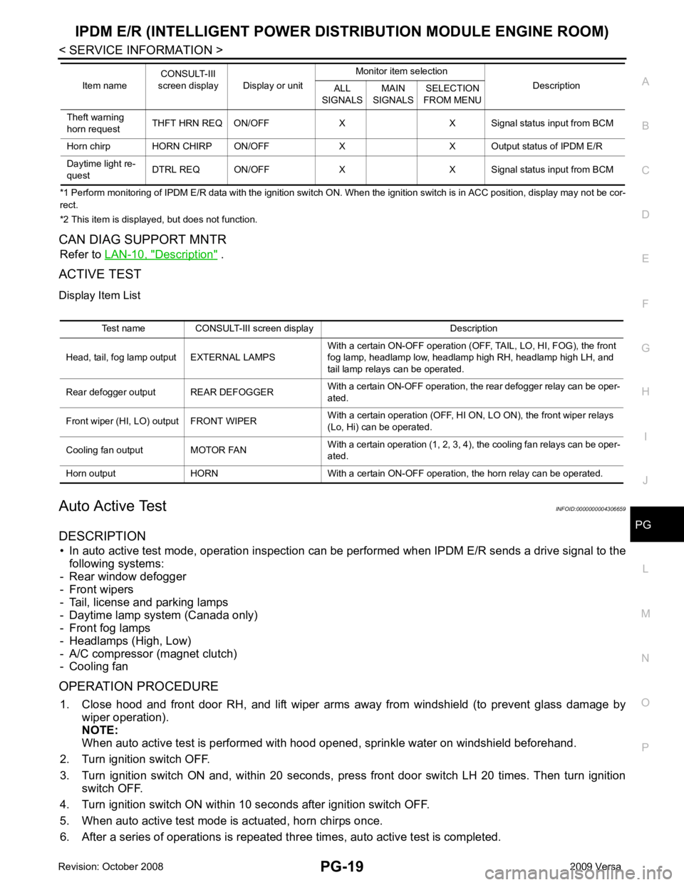
*1 Perform monitoring of IPDM E/R data with the ignition switch ON. When the ignition switch is in ACC position, display may no
t be cor-
rect.
*2 This item is displayed, but does not function.
CAN DIAG SUPPORT MNTR Refer to LAN-10, " Description " .
ACTIVE TEST
Display Item List
Auto Active Test INFOID:0000000004306659
DESCRIPTION • In auto active test mode, operation inspection can be performed when IPDM E/R sends a drive signal to the
following systems:
- Rear window defogger
- Front wipers
- Tail, license and parking lamps
- Daytime lamp system (Canada only)
- Front fog lamps
- Headlamps (High, Low)
- A/C compressor (magnet clutch)
- Cooling fan
OPERATION PROCEDURE 1. Close hood and front door RH, and lift wiper arms away from windshield (to prevent glass damage by
wiper operation).
NOTE:
When auto active test is performed with hood opened, sprinkle water on windshield beforehand.
2. Turn ignition switch OFF.
3. Turn ignition switch ON and, within 20 seconds, pre ss front door switch LH 20 times. Then turn ignition
switch OFF.
4. Turn ignition switch ON within 10 seconds after ignition switch OFF.
5. When auto active test mode is actuated, horn chirps once.
6. After a series of operations is repeated th ree times, auto active test is completed.
Theft warning
horn request THFT HRN REQ ON/OFF X X Signal status input from BCM
Horn chirp HORN CHIRP ON/OFF X X O utput status of IPDM E/R
Daytime light re-
quest DTRL REQ ON/OFF X X Signal
status input from BCM
Item name
CONSULT-III
screen display Display or unit Monitor item selection
Description
ALL
SIGNALS MAIN
SIGNALS SELECTION
FROM MENU Test name CONSULT-III screen display Description
Head, tail, fog lamp output EXTERNAL LAMPS With a certain ON-OFF operation (OFF, TAIL, LO, HI, FOG), the front
fog lamp, headlamp low, headlamp high RH, headlamp high LH, and
tail lamp relays can be operated.
Rear defogger output REAR DEFOGGER With a certain ON-OFF operation, the rear defogger relay can be oper-
ated.
Front wiper (HI, LO) output FRONT WIPER With a certain operation (OFF, HI ON, LO ON), the front wiper relays
(Lo, Hi) can be operated.
Cooling fan output MOTOR FAN With a certain operation (1, 2, 3, 4), the cooling fan relays can be oper-
ated.
Horn output HORN With a certain ON-OFF operation, the horn relay can be operated.
Page 4003 of 4331
Door Switch Check (Hatchback) " when the auto active test cannot be
performed.
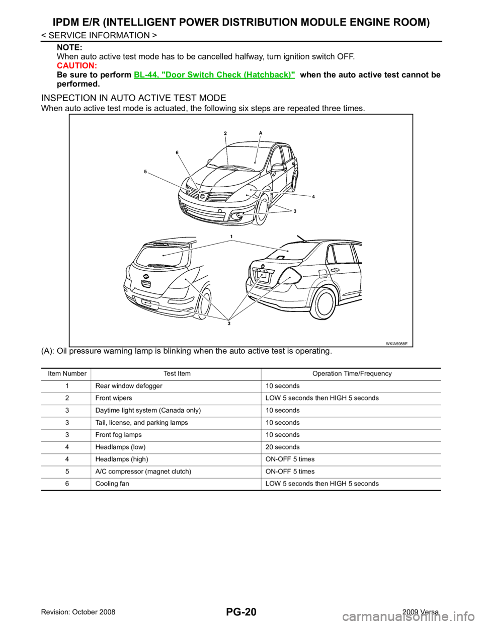
INSPECTION IN AUTO ACTIVE TEST MODE
When auto active test mode is actuated, t he following six steps are repeated three times.
(A): Oil pressure warning lamp is blin king when the auto active test is operating.
Page 4035 of 4331
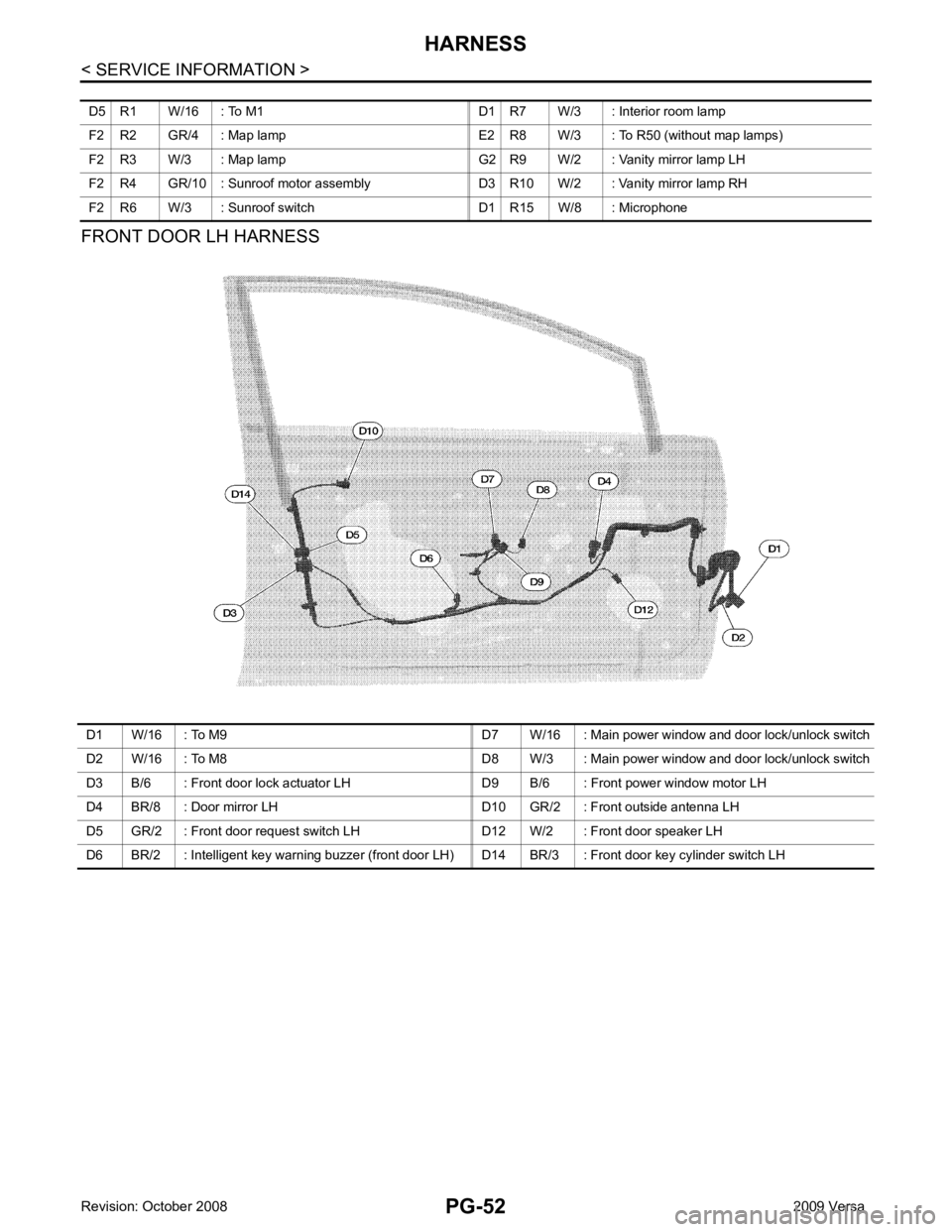
D1 W/16 : To M9 D7 W/16 : Main power window and door lock/unlock switch
D2 W/16 : To M8 D8 W/3 : Main power window and door lock/unlock switch
D3 B/6 : Front door lock actuator LH D9 B/6 : Front power window motor LH
D4 BR/8 : Door mirror LH D10 GR/2 : Front outside antenna LH
D5 GR/2 : Front door request switch LH D12 W/2 : Front door speaker LH
D6 BR/2 : Intelligent key warning buzzer (front door LH) D14 BR/3 : Front door key cylinder switch LH
Page 4040 of 4331

PG
N
O P
Wiring Diagram Codes (Cell Codes)
INFOID:0000000004306667
Use the chart below to find out what each wiring diagram code stands for.
Refer to the wiring diagram code in the alphabetical index to find the location (page number) of each wiring
diagram. D4 D405 W/4 : Back door lock assembly C2 D413 B/1 : Rear window defogger (-)
D4 D406 W/2 : Back door request switch F3 D414 — : Body ground
E2 D407 W/2 : High mounted stop lamp Code Section Wiring Diagram Name
ABS BRC Anti-lock Brake System
A/C,M MTC Manual Air Conditioner
APPS1 EC Accelerator Pe dal Position Sensor
A/F EC Air Fuel Ratio Sensor 1
A/FH EC Air Fuel Ratio Sensor 1 Heater
APPS2 EC Accelerator Pe dal Position Sensor
APPS3 EC Accelerator Pe dal Position Sensor
ASC/BS EC ASCD Brake Switch
ASC/SW EC ASCD Steering Switch
ASCBOF EC ASCD Brake Switch
ASCIND EC ASCD Indicator
AT/IND DI A/T Indicator Lamp
AUDIO AV Audio
BACK/L LT Back-up Lamp
BA/FTS AT A/T Fluid Temperature Sensor and TCM Power Supply
B/DOOR BL Back Door Opener
BRK/SW EC Brake Switch
CAN AT CAN Communication Line
CAN CVT CAN Comm unication Line
CAN EC CAN Communication Line
CAN LAN CAN System
CHARGE SC Charging System
CHIME DI Warning Chime
COOL/F EC Cooling Fan Control
COMBSW LT Combination Switch
CVTIND DI CVT Indicator Lamp
D/LOCK BL Power Door Lock
DEF GW Rear Window Defogger
DTRL LT Headlamp - Wi th Daytime Light System
ECTS EC Engine Coolant Temperature Sensor
ENGSS AT Engine Speed Signal
EPS STC Electronic Controlled Power Steering
ETC1 EC Electric Throttle Control Function
ETC2 EC Throttle Control Motor Relay
ETC3 EC Throttle Control Motor
F/FOG LT Front Fog Lamp
F/PUMP EC Fuel Pump
FTS AT A/T Fluid Temperature Sensor
FTS CVT CVT Fluid Temperature Sensor Circuit
FTTS EC Fuel Tank Temperature Sensor
FUEL EC Fuel Ignition System Function
HEATER MTC Heater System
Page 4042 of 4331

PG
N
O P
STM CVT Step Motor
STOP/L LT Stop Lamp
TCV AT Torque Converter Clutch Solenoid Valve
TCV CVT Torque Converter Clutch Solenoid Valve
T/LID BL Trunk Lid Opener
T/WARN WT Low Tire Pr essure Warning System
TAIL/L LT Parking, License and Tail Lamps
TPS1 EC Throttle Position Sensor
TPS2 EC Throttle Position Sensor
TPS3 EC Throttle Position Sensor
TURN LT Turn Signal and Hazard Warning Lamps
VEHSEC BL Vehicle Security (Theft Warning) System
VENT/V EC EVAP Canister Vent Control Valve
VSSA/T AT Vehicle Speed Sensor A/T (Revolution Sensor)
VSSMTR AT Vehicle Speed Sensor MTR
WARN DI Warning Lamps
WINDOW GW Power Window
WIP/R WW Rear Wiper and Washer
WIPER WW Front Wiper and Washer
Page 4118 of 4331
RSU
N
O P
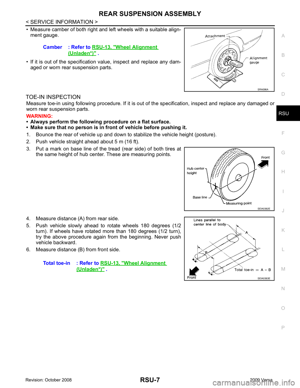
• Measure camber of both right and left wheels with a suitable align-
ment gauge.
• If it is out of the specificati on value, inspect and replace any dam-
aged or worn rear suspension parts.
TOE-IN INSPECTION Measure toe-in using following procedure. If it is out of the specification, inspect and replace any damaged or
worn rear suspension parts.
WARNING:
• Always perform the following procedure on a flat surface.
• Make sure that no person is in fron t of vehicle before pushing it.
1. Bounce the rear of vehicle up and down to stabilize the vehicle height (posture).
2. Push vehicle straight ahead about 5 m (16 ft).
3. Put a mark on base line of the tread (rear side) of both tires at the same height of hub center. These are measuring points.
4. Measure distance (A) from rear side.
5. Push vehicle slowly ahead to rotate wheels 180 degrees (1/2 turn). If wheels have rotated more than 180 degrees (1/2 turn),
try the above procedure again from the beginning. Never push
vehicle backward.
6. Measure distance (B) from front side. Camber : Refer to
RSU-13, " Wheel Alignment
(Unladen*) " .
SEIA0362E
Wheel Alignment
(Unladen*) " .
Page 4127 of 4331
SB
N
O P
• After replacing or reinstalling front seat belt
pre-tensioner assembly, or reconnecting front seat belt
pre-tensioner connector, check th e system function. Refer to SRS-19, " SRS Operation Check " .
• Do not disassemble buckle or seat belt assembly.
• Do not reuse seat belt anchor bolts after removal. Replace with new ones.
• Replace anchor bolts if th ey are deformed or worn out.
• Never oil tongue and buckle.
• If any component of seat belt assembly is questio nable, do not repair. Replace the whole seat belt
assembly.
• If webbing is cut, frayed, or damaged, replace seat belt assembly.
• When replacing seat belt assembly, u se a genuine NISSAN seat belt assembly.
AFTER A COLLISION WARNING:
• Inspect all seat belt assemblies including retractors and attaching hardware after any collision.
• NISSAN recommends that all seat belt assemblies in use during a collision be replaced unless the
collision was minor and the belts show no damage and continue to operate properly. Failure to do so
could result in serious personal injury in an acci dent. Seat belt assemblies not in use during a colli-
sion should also be replaced if either damage or im proper operation is noted. Seat belt pre-tensioner
should be replaced even if the seat belts are not in use during a frontal collision in which the air bags
are deployed.
Replace any seat belt assembly (including anchor bolts) if:
• The seat belt was in use at the time of a collision (except for minor collisions and the belts, retractors and
buckles show no damage and continue to operate properly).
• The seat belt was damaged in an accident. (i.e. torn webbing, bent retractor or guide).
• The seat belt attaching point was damaged in an accident. Inspect the seat belt attaching area for damage or distortion and repair as necessary before installing a new seat belt assembly.
• Anchor bolts are deformed or worn out.
• The seat belt pre-tensioner should be replaced even if t he seat belts are not in use during the collision in
which the air bags are deployed.