Page 663 of 4331

BL-202< SERVICE INFORMATION >
TRUNK LID OPENER
43 5
R Back door switch Input OFF ON (open) 0V
OFF (closed) Ba ttery voltage
44 5
LG Rear wiper auto stop Input ON Rear wiper operating 0
Rear wiper stopped Battery
45 7
GR Lock switch Input OFF ON (lock) 0V
OFF Battery voltage
46 7
L Unlock switch Input OFF ON (unlock) 0V
OFF Battery voltage
47 BR Front door switch LH Input OFF ON (open) 0V
OFF (closed) Ba ttery voltage
48 O Rear door switch LH Input OFF ON (open) 0V
OFF (closed) Ba ttery voltage
49 P Luggage room lamp Output OFF Any door open (ON) 0V
All doors closed (OFF) Battery voltage
50 SB A/C indicator Output ON A/C OFF 0
A/C ON Battery voltage
53 5
RBack door lock assem-
bly (actuator) Output OFF Back door (open) Battery voltage
53 6
RTrunk lamp switch and
trunk release solenoid Output OFF Trunk lid (open) Battery voltage
55 5
VRear wiper motor out-
put Output ONOFF 0
ON Battery voltage
56 R Battery saver output Output OFF
30 minutes after ignition
switch is turned OFF 0V
ON — Battery voltage
57 LG Battery power supply Input OFF — Battery voltage
59 7
GFront door lock actua-
tor LH (unlock) Output OFFOFF (neutral) 0V
ON (unlock) Battery voltage
60 V Turn signal (left) Output ON Turn left ON
61 W Turn signal (right) Output ON Turn right ON
63 BR Interior room lamp Output OFF Any door
switch ON (open) 0V
OFF (closed) Battery voltage
Terminal
Wire
color Signal name Signal
input/
output Measuring condition
Reference value or waveform
(Approx.)
Ignition
switch Operation or condition SKIA3009J
SKIA3009J
Page 668 of 4331
TRUNK LID OPENER
BL-207
< SERVICE INFORMATION >
C
D E
F
G H
J
K L
M A
B BL
N
O P
OK >> GO TO 2.
NG >> If fuse is blown, be sure to eliminate caus e of malfunction before installing new fuse. Refer to PG-3, " Schematic " .
2.
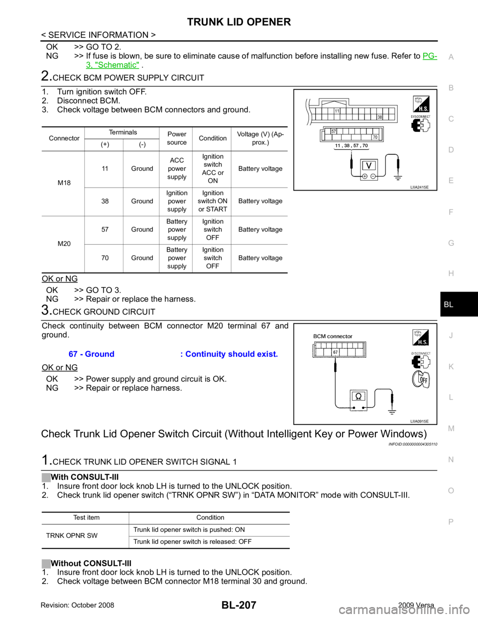
CHECK BCM POWER SUPPLY CIRCUIT
1. Turn ignition switch OFF.
2. Disconnect BCM.
3. Check voltage between BCM connectors and ground.
OK or NG OK >> GO TO 3.
NG >> Repair or replace the harness. 3.
CHECK GROUND CIRCUIT
Check continuity between BCM connector M20 terminal 67 and
ground.
OK or NG OK >> Power supply and ground circuit is OK.
NG >> Repair or replace harness.
Check Trunk Lid Opener Switch Circuit (Wit hout Intelligent Key or Power Windows)
INFOID:00000000043051101.
CHECK TRUNK LID OPENER SWITCH SIGNAL 1
With CONSULT-III
1. Insure front door lock knob LH is turned to the UNLOCK position.
2. Check trunk lid opener switch (“TRNK OPNR SW”) in “DATA MONITOR” mode with CONSULT-III.
Without CONSULT-III
1. Insure front door lock knob LH is turned to the UNLOCK position.
2. Check voltage between BCM connector M18 terminal 30 and ground. Connector
Terminals
Power
source Condition Voltage (V) (Ap-
prox.)
(+) (-)
M18 11 Ground
ACC
power
supply Ignition
switch
ACC or ON Battery voltage
38 Ground Ignition
power
supply Ignition
switch ON
or START Battery voltage
M20 57 Ground
Battery
power
supply Ignition
switch OFF Battery voltage
70 Ground Battery
power
supply Ignition
switch OFF Battery voltage LIIA2415E
67 - Ground : Continuity should exist.
LIIA0915E
Test item Condition
TRNK OPNR SW Trunk lid opener switch is pushed: ON
Trunk lid opener switch is released: OFF
Page 671 of 4331
BL-210< SERVICE INFORMATION >
TRUNK LID OPENER
OK or NG OK >> Check the condition of harness and connector.
NG >> Replace BCM. Refer to BCS-18, " Removal and Installa-
tion of BCM " .
Check Trunk Lid Opener Switch Circuit (W ithout Intelligent Key, with Power Windows)
INFOID:00000000043051111.
CHECK TRUNK LID OPENER SWITCH SIGNAL 1
With CONSULT-III
1. Insure front door lock knob RH is turned to the UNLOCK position.
2. Check trunk lid opener switch (“TRNK OPNR SW ”) in “DATA MONITOR” mode with CONSULT-III.
Without CONSULT-III
1. Insure front door lock knob RH is turned to the UNLOCK position.
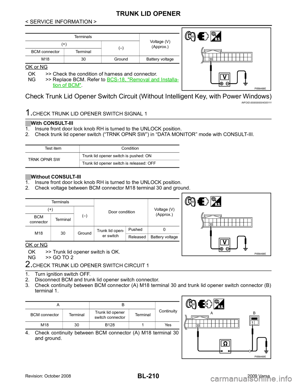
2. Check voltage between BCM connector M18 terminal 30 and ground.
OK or NG OK >> Trunk lid opener switch is OK.
NG >> GO TO 2 2.
CHECK TRUNK LID OPENER SWITCH CIRCUIT 1
1. Turn ignition switch OFF.
2. Disconnect BCM and trunk lid opener switch connector.
3. Check continuity between BCM connector (A) M18 terminal 30 and trunk lid opener switch connector (B)
terminal 1.
4. Check continuity between BCM connector (A) M18 terminal 30
and ground. Terminals
Voltage (V)
(Approx.)
(+)
(–)
BCM connector Terminal
M18 30 Ground Battery voltage PIIB6468E
Test item Condition
TRNK OPNR SW Trunk lid opener switch is pushed: ON
Trunk lid opener switch is released: OFF Terminals
Door conditionVoltage (V)
(Approx.)
(+)
(–)
BCM
connector Terminal
M18 30 Ground Trunk lid open-
er switch Pushed 0
Released Battery voltage PIIB6468E
A B
Continuity
BCM connector Terminal Trunk lid opener
switch connector Terminal
M18 30 B128 1 Yes PIIB6469E
Page 675 of 4331
BL-214< SERVICE INFORMATION >
TRUNK LID OPENER
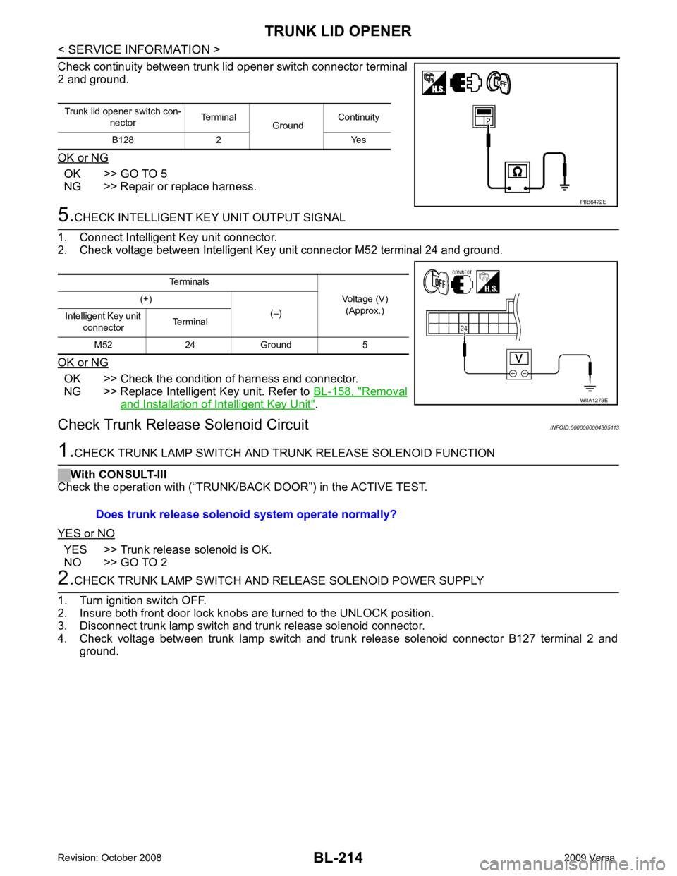
Check continuity between trunk lid opener switch connector terminal
2 and ground.
OK or NG OK >> GO TO 5
NG >> Repair or replace harness. 5.
CHECK INTELLIGENT KEY UNIT OUTPUT SIGNAL
1. Connect Intelligent Key unit connector.
2. Check voltage between Intelligent Key unit connector M52 terminal 24 and ground.
OK or NG OK >> Check the condition of harness and connector.
NG >> Replace Intelligent Key unit. Refer to BL-158, " Removal
and Installation of Intelligent Key Unit " .
Check Trunk Releas e Solenoid Circuit INFOID:00000000043051131.
CHECK TRUNK LAMP SWITCH AND T RUNK RELEASE SOLENOID FUNCTION
With CONSULT-III
Check the operation with (“TRUNK/BACK DOOR”) in the ACTIVE TEST.
YES or NO YES >> Trunk release solenoid is OK.
NO >> GO TO 2 2.
CHECK TRUNK LAMP SWITCH AND RE LEASE SOLENOID POWER SUPPLY
1. Turn ignition switch OFF.
2. Insure both front door lock knobs are turned to the UNLOCK position.
3. Disconnect trunk lamp switch and trunk release solenoid connector.
4. Check voltage between trunk lamp switch and trunk release solenoid connector B127 terminal 2 and ground.
Trunk lid opener switch con-
nector Terminal
GroundContinuity
B128 2 Yes PIIB6472E
Terminals
Voltage (V)(Approx.)
(+)
(–)
Intelligent Key unit
connector Terminal
M52 24 Ground 5 WIIA1279E
Does trunk release solenoid
system operate normally?
Page 680 of 4331
BL
N
O P
System Description
INFOID:0000000004305116
DESCRIPTION
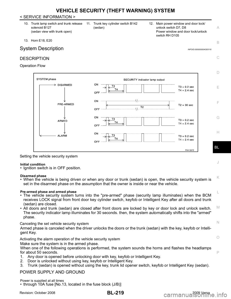
Operation Flow
Setting the vehicle security system Initial condition
• Ignition switch is in OFF position.
Disarmed phase
• When the vehicle is being driven or when any door or tr unk (sedan) is open, the vehicle security system is
set in the disarmed phase on the assumption that the owner is inside or near the vehicle.
Pre-armed phase and armed phase
• The vehicle security system turns into the "pre- armed" phase (security lamp illuminates) when the BCM
receives LOCK signal from front door key cylinder s witch, keyfob or Intelligent Key after all doors and trunk
(sedan) are closed.
• All doors and trunk (sedan) are closed after front door s are locked by key or door lock and unlock switch.
The security indicator lamp illuminates for 30 seconds. t hen, the system automatically shifts into the "armed"
phase.
Canceling the set vehicle security system Armed phase is canceled when the driver unlocks the doors or the trunk (sedan) with the key, keyfob or Intelli-
gent Key.
Activating the alarm operation of the vehicle security system Make sure the system is in the armed phase.
When one of the following operations is performed, the system sounds the horns and flashes the headlamps
for about 50 seconds.
1. Any door is opened before unlocking door with key, keyfob or Intelligent Key.
2. Door is unlocked without using key, keyfob or Intelligent Key.
3. Trunk (sedan) is opened without using the key, trunk lid opener switch, keyfob or Intelligent Key (sedan).
POWER SUPPLY AND GROUND
Power is supplied at all times
• through 10A fuse [No.13, located in the fuse block (J/B)] 10. Trunk lamp switch and trunk release
solenoid B127
(sedan view with trunk open) 11. Trunk key cylinder switch B142
(sedan) 12. Main power window and door lock/
unlock switch D7, D8
Power window and door lock/unlock
switch RH D105
13. Horn E18, E20
Page 682 of 4331
BL
N
O P
• from IPDM E/R terminal 45
• to horn relay terminal 1.
The headlamp flashes and the horn sounds intermittently.
The alarm automatically turns off after 25 seconds or when BCM receives any signal from keyfob or Intelligent
Key.
CAN Communication System Description INFOID:0000000004305117
Refer to LAN-8 .
Page 688 of 4331
VEHICLE SECURITY (THEFT WARNING) SYSTEM
BL-227
< SERVICE INFORMATION >
C
D E
F
G H
J
K L
M A
B BL
N
O P
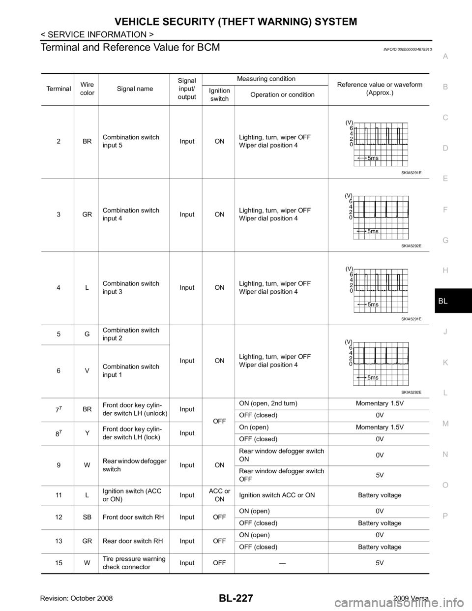
Terminal and Reference Value for BCM
INFOID:0000000004678913
Terminal Wire
color Signal name Signal
input/
output Measuring condition
Reference value or waveform
(Approx.)
Ignition
switch Operation or condition
2 BR Combination switch
input 5 Input ONLighting, turn, wiper OFF
Wiper dial position 4
3 GR Combination switch
input 4 Input ONLighting, turn, wiper OFF
Wiper dial position 4
4 L Combination switch
input 3 Input ONLighting, turn, wiper OFF
Wiper dial position 4
5 G Combination switch
input 2
Input ONLighting, turn, wiper OFF
Wiper dial position 4
6 V Combination switch
input 1
7 7
BRFront door key cylin-
der switch LH (unlock) Input
OFFON (open, 2nd turn) Momentary 1.5V
OFF (closed) 0V
8 7
YFront door key cylin-
der switch LH (lock) InputOn (open) Momentary 1.5V
OFF (closed) 0V
9 W Rear window defogger
switch Input ONRear window defogger switch
ON 0V
Rear window defogger switch
OFF 5V
11 L Ignition switch (ACC
or ON) InputACC or
ON Ignition switch ACC or ON Battery voltage
12 SB Front door switch RH Input OFF ON (open) 0V
OFF (closed) Battery voltage
13 GR Rear door switch RH Input OFF ON (open) 0V
OFF (closed) Battery voltage
15 W Tire pressure warning
check connector Input OFF — 5V SKIA5291E
SKIA5292E
SKIA5291E
SKIA5292E
Page 689 of 4331
BL-228< SERVICE INFORMATION >
VEHICLE SECURITY (T
HEFT WARNING) SYSTEM
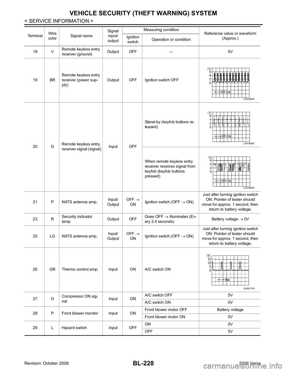
18 V Remote keyless entry
receiver (ground) Output OFF — 0V
19 BR Remote keyless entry
receiver (power sup-
ply) Output OFF Ignition switch OFF
20 G Remote keyless entry
receiver signal (signal) Input OFFStand-by (keyfob buttons re-
leased)
When remote keyless entry
receiver receives signal from
keyfob (keyfob buttons
pressed)
21 P NATS antenna amp. Input/
Output OFF
→
ON Ignition switch (OFF
→ ON) Just after turning ignition switch
ON: Pointer of tester should
move for approx. 1 second, then return to battery voltage.
23 R Security indicator
lamp Output OFFGoes OFF
→ illuminates (Ev-
ery 2.4 seconds) Battery voltage
→ 0V
25 LG NATS antenna amp. Input/
Output OFF
→
ON Ignition switch (OFF
→ ON) Just after turning ignition switch
ON: Pointer of tester should
move for approx. 1 second, then
return to battery voltage.
26 GR Thermo control amp. Input ON A/C switch ON
27 O Compressor ON sig-
nal Input ONA/C switch OFF 5V
A/C switch ON 0V
28 P Front blower monitor Input ON Front blower motor OFF Battery voltage
Front blower motor ON 0V
29 L Hazard switch Input OFF ON 0V
OFF 5V
Terminal
Wire
color Signal name Signal
input/
output Measuring condition
Reference value or waveform
(Approx.)
Ignition
switch Operation or condition LIIA1893E
LIIA1894E
LIIA1895E
ZJIA0719J