2009 MERCEDES-BENZ GL SUV ECU
[x] Cancel search: ECUPage 180 of 309
temperature, or for about 30 minutes if the
engine is not at normal operating temper-
ature (if you had started the engine only
briefly), before measuring.
i If you wish to cancel the measurement,
press the *or& button on the multi-
function steering wheel.
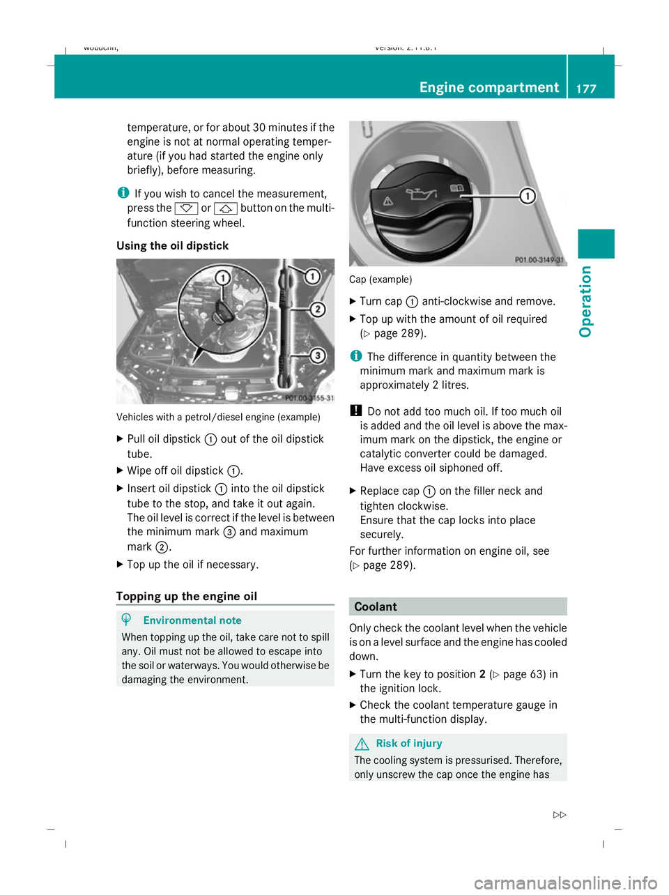
Using the oil dipstick Vehicles with a petrol/diesel engine (example)
X Pull oil dipstick :out of the oil dipstick
tube.
X Wipe off oil dipstick :.
X Insert oil dipstick :into the oil dipstick
tube to the stop, and take it out again.
The oil level is correct if the level is between
the minimum mark =and maximum
mark ;.
X Top up the oil if necessary.
Topping up the engine oil H
Environmental note
When topping up the oil, take care not to spill
any. Oil must not be allowed to escape into
the soil or waterways. You would otherwise be
damaging the environment. Cap (example)
X
Turn cap :anti-clockwise and remove.
X Top up with the amount of oil required
(Y page 289).
i The difference in quantity between the
minimum mark and maximum mark is
approximately 2 litres.
! Do not add too much oil. If too much oil
is added and the oil level is above the max-
imum mark on the dipstick, the engine or
catalytic converter could be damaged.
Have excess oil siphoned off.
X Replace cap :on the filler neck and
tighten clockwise.
Ensure that the cap locks into place
securely.
For further information on engine oil, see
(Y page 289). Coolant
Only check the coolant level when the vehicle
is on a level surface and the engine has cooled
down.
X Turn the key to position 2(Y page 63) in
the ignition lock.
X Check the coolant temperature gauge in
the multi-function display. G
Risk of injury
The cooling system is pressurised. Therefore,
only unscrew the cap once the engine has Engine compartment
177Operation
X164_AKB; 2; 3, en-GB
wobuchh,V ersion: 2.11.8.1
2009-03-31T14:14:58+02:00 - Seite 177 Z
Dateiname: 6515431202_buchblock.pdf; erzeugt am 01. Apr 2009 00:17:46; WK
Page 192 of 309
G
Risk of accident
Grains of sand, particles of dirt and other
abrasive materials can enter the brake sys-
tem. This can lead to excessive wear and
unpredictable braking efficiency.
After the brakes have been exposed to dirty
conditions, have them checked and cleaned
at a qualified specialist workshop, e.g. a
Mercedes-Benz Service Centre. Otherwise,
there is a risk that braking power may be
insufficient in the event of an emergency, or
that braking efficiency may be unpredictable.
Read this section before driving your vehicle
off-road. Practise by travelling over more gen-
tle off-road terrain first.
The following driving systems are specially
adapted to off-road driving:
R LOW RANGE off-road gear (Y page 114)
R off-road ABS (Y page 50)
R off-road 4-ETS (Y page 53)
R off-road ESP ®
(Y page 52)
R differential locks (Y page 116)
R DSR (Downhill Speed Regulation)
(Y page 113) Off-road driving
G
Risk of accident
Damage to the vehicle creates the risk of an
accident for yourself and other road users. If
in doubt, have your vehicle checked at a quali-
fied specialist workshop which has the nec-
essary specialist knowledge and tools to carry
out the work required. Mercedes-Benz rec-
ommends that you use a Mercedes-Benz
Service Centre for this purpose. H
Environmental note
Protection of the environment is of primary
importance. Treat nature with respect.
Observe all prohibiting signs. General information R
Stop your vehicle and, if necessary, select
the LOW RANGE off-road gear
(Y page 114) before driving off-road.
R Select a vehicle level suitable for the off-
road terrain. Make sure there is always suf-
ficient ground clearance to prevent dam-
age to the vehicle.
R Check that items of luggage and loads are
stowed safely and are well secured
(Y page 156).
R Always keep the engine running and in gear
when driving on a downhill gradient. Acti-
vate DSR.
R Drive slowly and evenly, if necessary at a
walking pace.
R Ensure that the wheels are in contact with
the ground at all times.
R Drive with extreme care on unknown off-
road routes where visibility is poor. For
safety reasons, get out of the vehicle first
and survey the off-road route.
R Check the depth of water before fording
rivers and streams.
R Look out for obstacles such as rocks, holes,
tree stumps and furrows.
R Always keep the side windows and the slid-
ing /tilting sunroof* closed during the jour-
ney.
R Do not stray from marked routes or paths.
i Information about retrofitting special all-
terrain tyres is available from any
Mercedes-Benz Service Centre.
Checklist before driving off-road X
Engine oil level: check the engine oil and
top it up if necessary.
X Vehicle toolkit: check that the jack is
working and make sure you have the wheel-
brace, a robust tow cable and a folding
spade in the vehicle. Off-road driving
189Operation
* optional
X164_AKB; 2; 3, en-GB
wobuchh,
Version: 2.11.8.1 2009-03-31T14:14:58+02:00 - Seite 189 Z
Dateiname: 6515431202_buchblock.pdf; erzeugt am 01. Apr 2009 00:17:49; WK
Page 197 of 309
X
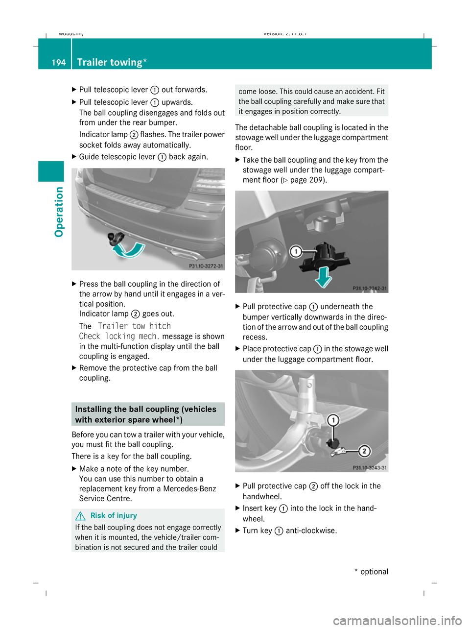
Pull telescopic lever :out forwards.
X Pull telescopic lever :upwards.
The ball coupling disengages and folds out
from under the rear bumper.
Indicator lamp ;flashes. The trailer power
socket folds away automatically.
X Guide telescopic lever :back again. X
Press the ball coupling in the direction of
the arrow by hand until it engages in a ver-
tical position.
Indicator lamp ;goes out.
The Trailer tow hitch
Check locking mech. message is shown
in the multi-function display until the ball
coupling is engaged.
X Remove the protective cap from the ball
coupling. Installing the ball coupling (vehicles
with exterior spare wheel*)
Before you can tow a trailer with your vehicle,
you must fit the ball coupling.
There is a key for the ball coupling.
X Make a note of the key number.
You can use this number to obtain a
replacement key from a Mercedes-Benz
Service Centre. G
Risk of injury
If the ball coupling does not engage correctly
when it is mounted, the vehicle/trailer com-
bination is not secured and the trailer could come loose. This could cause an accident. Fit
the ball coupling carefully and make sure that
it engages in position correctly.
The detachable ball coupling is located in the
stowage well under the luggage compartment
floor.
X Take the ball coupling and the key from the
stowage well under the luggage compart-
ment floor (Y page 209). X
Pull protective cap :underneath the
bumper vertically downwards in the direc-
tion of the arrow and out of the ball coupling
recess.
X Place protective cap :in the stowage well
under the luggage compartment floor. X
Pull protective cap ;off the lock in the
handwheel.
X Insert key :into the lock in the hand-
wheel.
X Turn key :anti-clockwise. 194
Trailer towing*Operation
* optional
X164_AKB; 2; 3, en-GB
wobuchh,
Version: 2.11.8.1 2009-03-31T14:14:58+02:00 - Seite 194
Dateiname: 6515431202_buchblock.pdf; erzeugt am 01. Apr 2009 00:17:51; WK
Page 198 of 309
i
The key remains inserted when you
remove the ball coupling. X
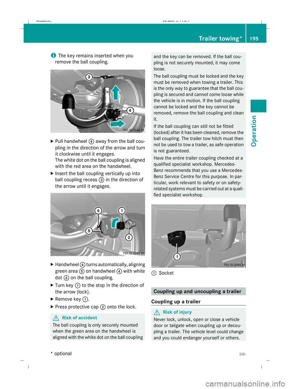
Pull handwheel ?away from the ball cou-
pling in the direction of the arrow and turn
it clockwise until it engages.
The white dot on the ball coupling is aligned
with the red area on the handwheel.
X Insert the ball coupling vertically up into
ball coupling recess =in the direction of
the arrow until it engages. X
Handwheel ?turns automatically, aligning
green area Aon handwheel ?with white
dot Bon the ball coupling.
X Turn key :to the stop in the direction of
the arrow (lock).
X Remove key :.
X Press protective cap ;onto the lock. G
Risk of accident
The ball coupling is only securely mounted
when the green area on the handwheel is
aligned with the white dot on the ball coupling and the key can be removed. If the ball cou-
pling is not securely mounted, it may come
loose.
The ball coupling must be locked and the key
must be removed when towing a trailer. This
is the only way to guarantee that the ball cou-
pling is secured and cannot come loose while
the vehicle is in motion. If the ball coupling
cannot be locked and the key cannot be
removed, remove the ball coupling and clean
it.
If the ball coupling can still not be fitted
(locked) after it has been cleaned, remove the
ball coupling. The trailer tow hitch must then
not be used to tow a trailer, as safe operation
is not guaranteed.
Have the entire trailer coupling checked at a
qualified specialist workshop. Mercedes-
Benz recommends that you use a Mercedes-
Benz Service Centre for this purpose. In par-
ticular, work relevant to safety or on safety-
related systems must be carried out at a quali-
fied specialist workshop. :
Socket Coupling up and uncoupling a trailer
Coupling up a trailer G
Risk of injury
Never lock, unlock, open or close a vehicle
door or tailgate when coupling up or decou-
pling a trailer. The vehicle level could change
and you could endanger yourself or others. Trailer towing*
195Operation
* optional
X164_AKB; 2; 3, en-GB
wobuchh,
Version: 2.11.8.1 2009-03-31T14:14:58+02:00 - Seite 195 Z
Dateiname: 6515431202_buchblock.pdf; erzeugt am 01. Apr 2009 00:17:51; WK
Page 199 of 309
Never press the ADS button* or operate the
level control* while you are coupling up or
decoupling a trailer.
X Make sure the DIRECT SELECT selector
lever is set to P.
X Depress the parking brake.
X Start the engine.
X Set the vehicle to highway level
(Y page 132).
X Set the adaptive damping system (ADS)
setting to AUTOorCOMF (Ypage 129).
X Switch off the engine.
X Close the doors and tailgate.
X Position the trailer level behind the vehicle.
X Couple up the trailer.
X Establish the electrical connection
between the vehicle and the trailer.
i If you have coupled a trailer, the vehicle
will remain at highway level.
The vehicle automatically lowers to high-
way level if you drive faster than 8 km/h
with a trailer. The vehicle is not lowered to
the high-speed level even if you are travel-
ling at higher speeds.
This also applies when using accessories
that are plugged into the socket of the
trailer coupling (e.g. a bicycle rack).
Decoupling a trailer G
Risk of injury
Do not disconnect a trailer with an engaged
overrun brake. Otherwise, your hand could
become trapped between the bumper and
drawbar.
! Do not uncouple a trailer with overrun
brake between the bumper and drawbar,
otherwise your vehicle could be damaged
by the spring action of the overrun brake. X
Make sure the DIRECT SELECT selector
lever is set to P.
X Depress the parking brake.
X Start the engine.
X Close the doors and tailgate.
X Secure the trailer against rolling away. G
Risk of injury
The vehicle is lowered as soon as you discon-
nect the trailer cable. Make sure that nobody
is in the vicinity of the wheel arch or the
underbody. You could otherwise trap yourself
or others.
As soon as you decouple the trailer, the unla-
den vehicle rises slightly. Make sure that you
or others are not injured in the process.
X Remove the trailer cable and decouple the
trailer.
X Switch off the engine. Notes on towing a trailer
G
Risk of accident
When reversing the vehicle towards the
trailer, make sure there is nobody between
the trailer and the vehicle.
Couple and uncouple the trailer carefully. If
you do not couple the trailer to the towing
vehicle correctly, the trailer could become
detached.
Make sure that the following values are not
exceeded:
R the permissible trailer drawbar noseweight
R the permissible trailer load
R the permissible rear axle load of the towing
vehicle
R the maximum permissible gross vehicle
weight of both the towing vehicle and the
trailer
You will find the applicable permissible val-
ues, which must not be exceeded, in the vehi-
cle documents. 196
Trailer towing*Operation
* optional
X164_AKB; 2; 3, en-GB
wobuchh
,V ersion: 2.11.8.1
2009-03-31T14:14:58+02:00 - Seite 196
Dateiname: 6515431202_buchblock.pdf; erzeugt am 01. Apr 2009 00:17:51; WK
Page 202 of 309

G
Risk of accident
Do not carry the ball coupling in the vehicle
interior if it is not secured.
Otherwise, you and others could be injured by
the ball coupling being thrown around if you:
R brake sharply
R change direction suddenly
R are involved in an accident
Information on cleaning and care of the trailer
coupling can be found at (Y page 203).Trailer power supply
When it leaves the factory, your vehicle's
trailer socket outlet is equipped with a per-
manent power supply and a power supply that
is switched on via the ignition lock.
The permanent power supply is supplied via
trailer socket pin 9.
The power supply that is switched on via the
ignition lock is supplied via trailer socket
pin 10.
! You can connect consumers with a power
rating of up to 240 W to the permanent
power supply and up to 180 W to the power
supply that is switched on via the ignition
lock.
You must not charge a trailer battery using
the power supply.
The trailer's turn signal lamps are only guar-
anteed to function when bulbs are used.
You can obtain further information about
installing the trailer electrics from a qualified
specialist workshop, e.g. a Mercedes-Benz
Service Centre.
X To switch the connected power supply
on or off: turn the key in the ignition lock
to position 2or 0, respectively. Trailer with 7-pin connector
If your trailer has a 7-pin connector, you can
connect it to the 13-pin socket on the ball
coupling using an adapter or, if necessary, an
adapter cable. Both of these can be obtained
at a qualified specialist workshop, e.g. at a
Mercedes-Benz Service Centre.
Fitting the adapter X
Open the socket cover.
X Insert connector with lug :into
groove ;on the socket and turn the con-
nector clockwise to the stop.
X Make the cover engage.
X If you are using an adapter cable, secure
the cable to the trailer with cable ties.
! Make sure that there is sufficient cable
play so that the cable cannot become
detached when cornering. Service
ASSYST PLUS service interval display
The ASSYST PLUS service interval display
informs you of the next service due date.
The service due date is shown in the multi-
function display, for example:
Service A in .. days
Service A in .. km
Service A due now
The letter indicates how much time the work-
shop will require to carry out the service work. Service
199Operation
X164_AKB; 2; 3, en-GB
wobuchh, Version: 2.11.8.1 2009-03-31T14:14:58+02:00 - Seite 199 Z
Dateiname: 6515431202_buchblock.pdf; erzeugt am 01. Apr 2009 00:17:52; WK
Page 213 of 309
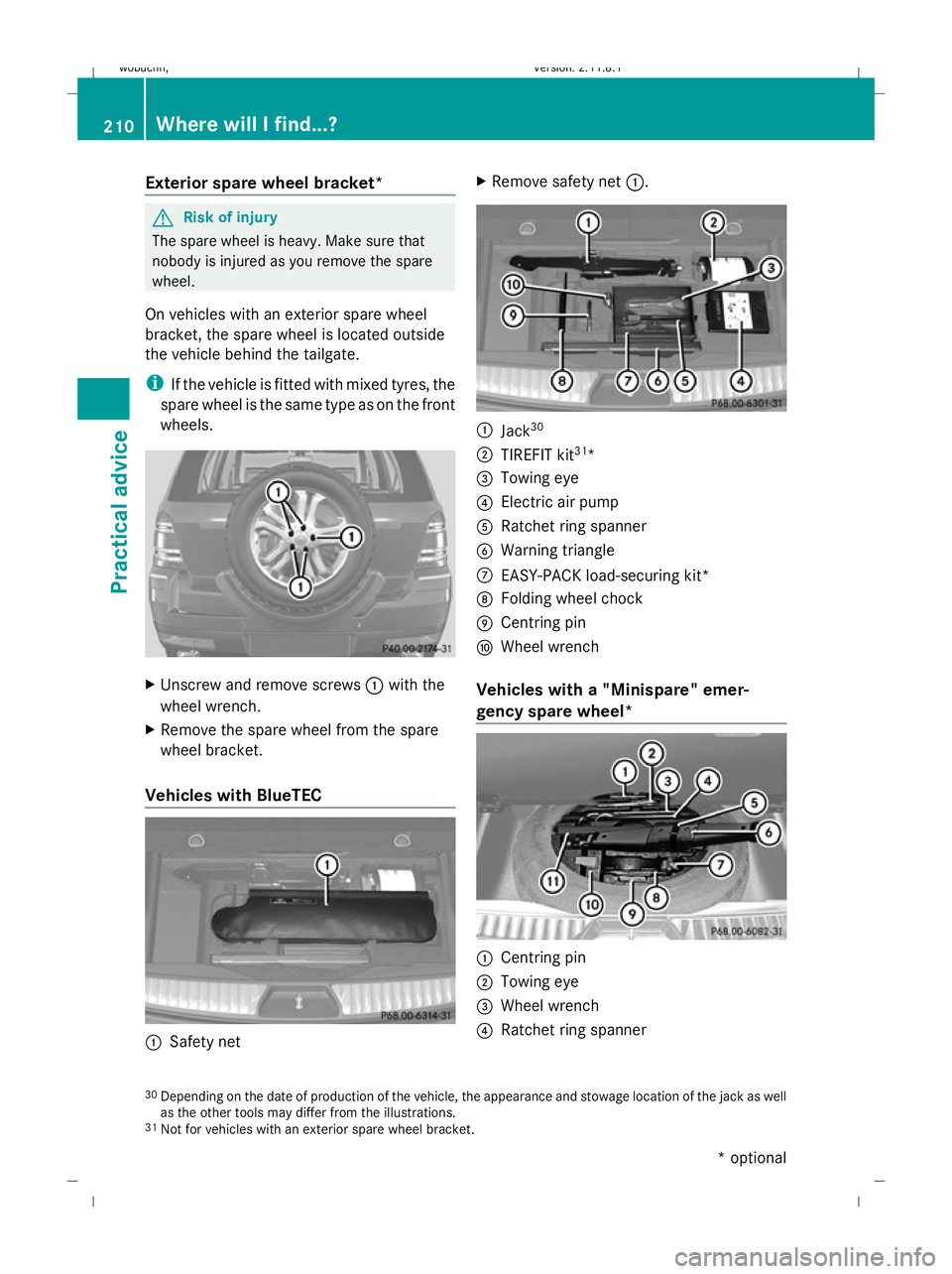
Exterior spare wheel bracket*
G
Risk of injury
The spare wheel is heavy. Make sure that
nobody is injured as you remove the spare
wheel.
On vehicles with an exterior spare wheel
bracket, the spare wheel is located outside
the vehicle behind the tailgate.
i If the vehicle is fitted with mixed tyres, the
spare wheel is the same type as on the front
wheels. X
Unscrew and remove screws :with the
wheel wrench.
X Remove the spare wheel from the spare
wheel bracket.
Vehicles with BlueTEC :
Safety net X
Remove safety net :. :
Jack 30
; TIREFIT kit 31
*
= Towing eye
? Electric air pump
A Ratchet ring spanner
B Warning triangle
C EASY-PACK load-securing kit*
D Folding wheel chock
E Centring pin
F Wheel wrench
Vehicles with a "Minispare" emer-
gency spare wheel* :
Centring pin
; Towing eye
= Wheel wrench
? Ratchet ring spanner
30 Depending on the date of production of the vehicle, the appearance and stowage location of the jack as well
as the other tools may differ from the illustrations.
31 Not for vehicles with an exterior spare wheel bracket. 210
Where will I find...?Practical advice
* optional
X164_AKB; 2; 3, en-GB
wobuchh,
Version: 2.11.8.1 2009-03-31T14:14:58+02:00 - Seite 210
Dateiname: 6515431202_buchblock.pdf; erzeugt am 01. Apr 2009 00:17:58; WK
Page 271 of 309

Changing a wheel and fitting the
spare wheel G
Risk of accident
The wheel dimensions and tyre size of the
"Minispare" emergency spare wheel *may dif-
fer from those of the damaged wheel.
Your vehicle's handling characteristics will
change when a "Minispare" emergency spare
wheel* is fitted. Adapt your style of driving
accordingly.
The "Minispare" emergency spare wheel*
may only be used for a short time. Do not
exceed the maximum speed of 80 km/h and
do not deactivate ESP ®
.
Never drive the vehicle with more than one
"Minispare" emergency spare wheel* fitted. G
Risk of accident
Have the "Minispare" emergency spare
wheel* or the spare wheel* replaced with a
new wheel as soon as possible at a qualified
specialist workshop which has the necessary
specialist knowledge and tools to carry out
the work required. Mercedes-Benz recom-
mends that you use a Mercedes-Benz Service
Centre for this purpose. In particular, work
relevant to safety or on safety-related sys-
tems must be carried out at a qualified spe-
cialist workshop.
Preparing the vehicle X
Prepare the vehicle as described
(Y page 262).
X If a trailer is coupled, uncouple it.
X Place the wheels in the straight-ahead posi-
tion.
X Remove the following items from the stow-
age well under the luggage compartment
floor:
R the wheel wrench
R the folding wheel chock
R the jack Use the folding wheel chock to prevent the
vehicle from rolling away.
X
Fold both plates :upwards.
X Fold out lower plate ;.
X Guide the lugs on the lower plate fully into
openings in base plate =. Securing the vehicle on level ground
X
On level ground: place the folding wheel
chock or similar under the wheel that is
diagonally opposite to the wheel you wish
to change. Securing the vehicle on slight downhill gradients268
Flat tyrePractical advice
* optional
X164_AKB; 2; 3, en-GB
wobuchh,
Version: 2.11.8.1 2009-03-31T14:14:58+02:00 - Seite 268
Dateiname: 6515431202_buchblock.pdf; erzeugt am 01. Apr 2009 00:18:11; WK