2009 INFINITI QX56 headlamp
[x] Cancel search: headlampPage 2055 of 4171

BCM (BODY CONTROL MODULE)EXL-107
< ECU DIAGNOSIS >
C
DE
F
G H
I
J
K
M A
B
EXL
N
O P
HEADLAMP SW1 Headlamp switch OFF OFF
Headlamp switch 1st
ON
HEADLAMP SW2 Headlamp switch OFF
OFF
Headlamp switch 1st ON
HI BEAM SW High beam switch OFF
OFF
High beam switch HI ON
H/L WASH SW NOTE:
The item is indicated, but not monitored OFF
IGN ON SW Ignition switch OFF or ACC
OFF
Ignition switch ON ON
IGN SW CAN Ignition switch OFF or ACC
OFF
Ignition switch ON ON
INT VOLUME Wiper intermittent dial is in a dial position 1 - 7 1 - 7
I-KEY LOCK LOCK button of Intelligent Key is not pressed
OFF
LOCK button of Intelligent Key is pressed ON
I-KEY UNLOCK UNLOCK button of Intelligent Key is not pressed
OFF
UNLOCK button of Intelligent Key is pressed ON
KEY ON SW Mechanical key is removed from key cylinder
OFF
Mechanical key is inserted to key cylinder ON
OIL PRESS SW • Ignition switch OFF or ACC
• Engine running
OFF
Ignition switch ON ON
PASSING SW Other than lighting switch PASS
OFF
Lighting switch PASS ON
REAR DEF SW Rear window defogger switch OFF
OFF
Rear window defogger switch ON ON
RKE LOCK AND UN-
LOCK NOTE:
The item is indicated, but not monitored OFF
ON
RR WASHER SW Rear washer switch OFF
OFF
Rear washer switch ON ON
RR WIPER INT Rear wiper switch OFF
OFF
Rear wiper switch INT ON
RR WIPER ON Rear wiper switch OFF
OFF
Rear wiper switch ON ON
RR WIPER STOP Rear wiper stop position
OFF
Other than rear wiper stop position ON
TAIL LAMP SW Lighting switch OFF
OFF
Lighting switch 1ST ON
TRNK OPNR SW When back door opener switch is not pressed
OFF
When back door opener switch is pressed ON
TURN SIGNAL L Turn signal switch OFF
OFF
Turn signal switch LH ON
TURN SIGNAL R Turn signal switch OFF
OFF
Turn signal switch RH ON
VEHICLE SPEED While driving Equivalent to speedo meter reading
Monitor Item
Condition Value/Status
Revision: December 20092009 QX56
Page 2073 of 4171

IPDM E/R (INTELLIGENT POWER DISTRIBUTION MODULE ENGINE ROOM)
EXL-125
< ECU DIAGNOSIS >
C
D E
F
G H
I
J
K
M A
B
EXL
N
O P
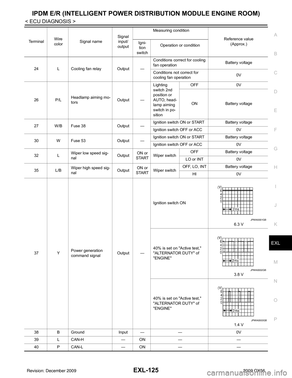
24 L Cooling fan relay Output — Conditions correct for cooling
fan operation
Battery voltage
Conditions not correct for
cooling fan operation 0V
26 P/L Headlamp aiming mo-
tors Output —Lighting
switch 2nd
position or
AUTO, head-
lamp aiming
switch in po-
sition OFF
0V
ON Battery voltage
27 W/B Fuse 38 Output —Ignition switch ON or START
Battery voltage
Ignition switch OFF or ACC 0V
30 W Fuse 53 Output —Ignition switch ON or START
Battery voltage
Ignition switch OFF or ACC 0V
32 L Wiper low speed sig-
nal OutputON or
START Wiper switch OFF
Battery voltage
LO or INT 0V
35 L/B Wiper high speed sig-
nal OutputON or
START Wiper switch OFF, LO, INT Battery voltage
HI 0V
37 Y Power generation
command signal
Output —Ignition switch ON
6.3 V
40% is set on "Active test,"
"ALTERNATOR DUTY" of
"ENGINE" 3.8 V
40% is set on "Active test,"
"ALTERNATOR DUTY" of
"ENGINE" 1.4 V
38 B Ground Input ——0V
39 L CAN-H — ON— —
40 P CAN-L — ON— —
Te r m i n a l
Wire
color Signal name Signal
input/
output Measuring condition
Reference value(Approx.)
Igni-
tion
switch Operation or condition
JPMIA0001GB
JPMIA0002GB
JPMIA0003GB
Revision: December 20092009 QX56
Page 2080 of 4171

EXL-132
< ECU DIAGNOSIS >
IPDM E/R (INTELLIGENT POWER DISTRIBUTION MODULE ENGINE ROOM)
If No CAN Communication Is Available With BCM
IGNITION RELAY MALFUNCTION DETECTION FUNCTION
• IPDM E/R monitors the voltage at the contact circuit and excitation coil circuit of the ignition relay inside it.
• IPDM E/R judges the ignition relay error if the voltage differs between the contact circuit and the excitation
coil circuit.
• If the ignition relay cannot turn OFF due to contact seizure, it activates the tail lamp relay for 10 minutes to alert the user to the ignition relay malfunction when the ignition switch is turned OFF.
NOTE:
The tail lamp turns OFF when the ignition switch is turned ON.
FRONT WIPER CONTROL
IPDM E/R detects front wiper stop posit ion by a front wiper auto stop signal.
When a front wiper auto stop signal is in the conditions listed below, IPDM E/R stops power supply to wiper
after repeating a front wiper 10 second activation and 20 second stop five times.
NOTE:
This operation status can be confirmed on the IPDM E/R “DATA MONITOR” that displays “Block” for the item
“WIP PROT” while the wiper is stopped.
STARTER MOTOR PROTECTION FUNCTION
IPDM E/R turns OFF the starter control relay to protect the starter motor when the starter control relay remains
active for 90 seconds.
Control part Fail-safe in operation
Cooling fan • Turns ON the cooling fan relay when the ignition switch is turned ON
• Turns OFF the cooling fan relay when the ignition switch is turned OFF
Control part
Fail-safe in operation
Headlamp • Turns ON the headlamp low relay when the ignition switch is turned ON
• Turns OFF the headlamp low relay when the ignition switch is turned OFF
• Headlamp high relay OFF
•Parking lamps
• License plate lamps
• Tail lamps • Turns ON the tail lamp relay when the ignition switch is turned ON
• Turns OFF the tail lamp relay when the ignition switch is turned OFF
Front wiper • The status just before activation of fail-safe control is maintained until the ignition
switch is turned OFF while the front wiper is operating at LO or HI speed.
• The wiper is operated at LO speed until the ignition switch is turned OFF if the fail- safe control is activated while the front wipe r is set in the INT mode and the front wiper
motor is operating.
Rear window defogger Rear window defogger relay OFF
A/C compressor A/C relay OFF
Front fog lamps Front fog lamp relay OFF
Ignition switch Ignition relayTail lamp relay
ON ON —
OFF OFF —
Ignition switchFront wiper switch Auto stop signal
ON OFF
Front wiper stop position signal cannot be
input 10 seconds.
ON The signal does not change for 10 seconds.
Revision: December 20092009 QX56
Page 2082 of 4171

EXL-134
< SYMPTOM DIAGNOSIS >
EXTERIOR LIGHTING SYSTEM SYMPTOMS
SYMPTOM DIAGNOSIS
EXTERIOR LIGHTING SYSTEM SYMPTOMS
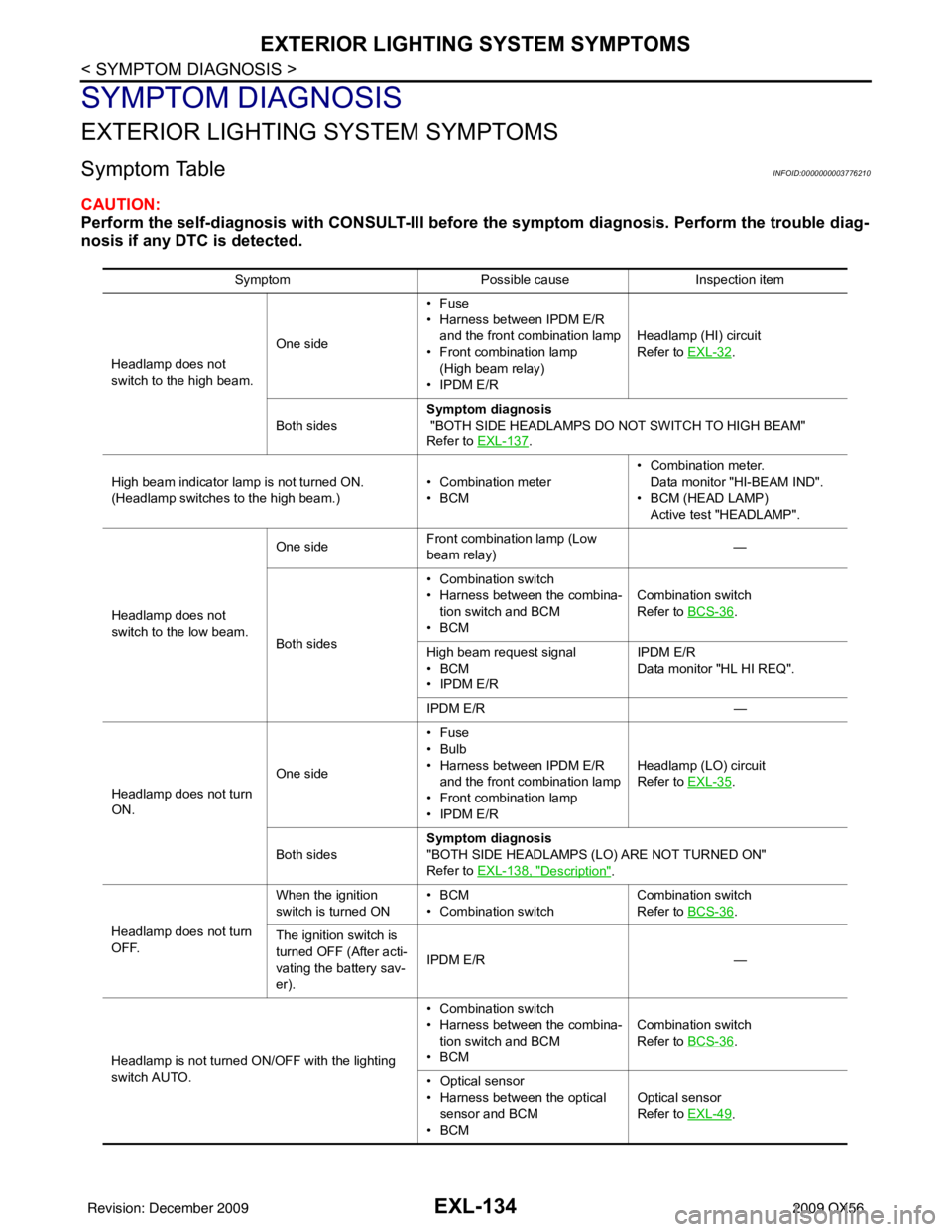
Symptom TableINFOID:0000000003776210
CAUTION:
Perform the self-diagnosis with CONSULT-III before the symptom diagnosis. Perform the trouble diag-
nosis if any DTC is detected.
Symptom Possible causeInspection item
Headlamp does not
switch to the high beam. One side•Fuse
• Harness between IPDM E/R
and the front combination lamp
• Front combination lamp
(High beam relay)
• IPDM E/R Headlamp (HI) circuit
Refer to EXL-32
.
Both sides Symptom diagnosis
"BOTH SIDE HEADLAMPS DO NOT SWITCH TO HIGH BEAM"
Refer to
EXL-137
.
High beam indicator lamp is not turned ON.
(Headlamp switches to the high beam.) • Combination meter
•BCM• Combination meter.
Data monitor "HI-BEAM IND".
• BCM (HEAD LAMP) Active test "HEADLAMP".
Headlamp does not
switch to the low beam. One side
Front combination lamp (Low
beam relay)
—
Both sides • Combination switch
• Harness between the combina-
tion switch and BCM
•BCM Combination switch
Refer to BCS-36
.
High beam request signal
•BCM
• IPDM E/R IPDM E/R
Data monitor "HL HI REQ".
IPDM E/R —
Headlamp does not turn
ON. One side•Fuse
•Bulb
• Harness between IPDM E/R
and the front combination lamp
• Front combination lamp
• IPDM E/R Headlamp (L
O) circuit
Refer to EXL-35
.
Both sides Symptom diagnosis
"BOTH SIDE HEADLAMPS (LO) ARE NOT TURNED ON"
Refer to
EXL-138, "
Description".
Headlamp does not turn
OFF. When the ignition
switch is turned ON
•BCM
• Combination switch Combination switch
Refer to BCS-36
.
The ignition switch is
turned OFF (After acti-
vating the battery sav-
er). IPDM E/R
—
Headlamp is not turned ON/OFF with the lighting
switch AUTO. • Combination switch
• Harness between the combina-
tion switch and BCM
•BCM Combination switch
Refer to BCS-36
.
• Optical sensor
• Harness between the optical sensor and BCM
•BCM Optical sensor
Refer to EXL-49
.
Revision: December 20092009 QX56
Page 2084 of 4171

EXL-136
< SYMPTOM DIAGNOSIS >
NORMAL OPERATING CONDITION
NORMAL OPERATING CONDITION
DescriptionINFOID:0000000003776211
XENON HEADLAMPS
The brightness and color of the light may vary slightly immediately after turning the headlamp ON. This condi-
tionwill remain until the xenon bulb becomes stable. This is normal.
• Illumination time lag may occur between right and left. This is normal.
AUTO LIGHT SYSTEM
The auto light system may not turn the headlamp ON/OF F immediately after passing a dark area or a bright
area (short tunnel, sky bridge, shadowed area etc.). This is normal.
Revision: December 20092009 QX56
Page 2085 of 4171

BOTH SIDE HEADLAMPS DO NOT SWITCH TO HIGH BEAM
EXL-137
< SYMPTOM DIAGNOSIS >
C
D E
F
G H
I
J
K
M A
B
EXL
N
O P
BOTH SIDE HEADLAMPS DO NOT SWITCH TO HIGH BEAM
DescriptionINFOID:0000000003776212
The headlamps (both sides) do not switch to high beam when the lighting switch is in the HI or PASS setting.
Diagnosis ProcedureINFOID:0000000003776213
1.COMBINATION SWITCH INSPECTION
Check the combination switch. Refer to BCS-36, "
Diagnosis Procedure".
Is the combination switch normal?
YES >> GO TO 2.
NO >> Repair or replace the malfunctioning part.
2.CHECK HEADLAMP (HI) REQUEST SIGNAL INPUT
CONSULT-III DATA MONITOR
1. Select "HL HI REQ" of IPDM E/R DATA MONITOR item.
2. With operating the lighting switch, check the monitor status.
Is the item status normal?
YES >> GO TO 3.
NO >> Replace BCM. Refer to BCS-56, "
Removal and Installation" .
3.HEADLAMP (HI) CIRCUIT INSPECTION
Check the headlamp (HI) circuit. Refer to EXL-32, "
Description".
Is the headlamp (HI) circuit normal?
YES >> Replace IPDM E/R. Refer to PCS-34, "Removal and Installation of IPDM E/R" .
NO >> Repair or replace the malfunctioning part.
Monitor item ConditionMonitor status
HL HI REQ Lighting switch
(2ND)HI or PASS
ON
Except for HI or
PA S S OFF
Revision: December 20092009 QX56
Page 2086 of 4171

EXL-138
< SYMPTOM DIAGNOSIS >
BOTH SIDE HEADLAMPS (LO) ARE NOT TURNED ON
BOTH SIDE HEADLAMPS (LO) ARE NOT TURNED ON
DescriptionINFOID:0000000003776214
The headlamps (both sides) do not turn ON in any lighting switch setting.
Diagnosis ProcedureINFOID:0000000003776215
1.CHECK COMBINATION SWITCH
Check the combination switch. Refer to BCS-36, "
Diagnosis Procedure".
Is the combination switch normal?
YES >> GO TO 2.
NO >> Repair or replace the malfunctioning part.
2.CHECK HEADLAMP (LO) REQUEST SIGNAL INPUT
CONSULT-III DATA MONITOR
1. Select "HL LO REQ" of IPDM E/R DATA MONITOR item.
2. With operating the lighting switch, check the monitor status.
Is the item status normal?
YES >> GO TO 3.
NO >> Replace BCM. Refer to BCS-56, "
Removal and Installation" .
3.HEADLAMP (LO) CIRCUIT INSPECTION
Check the headlamp (LO) circuit. Refer to EXL-35, "
Description".
Is the headlamp (LO) circuit normal?
YES >> Replace IPDM E/R. Refer to PCS-34, "Removal and Installation of IPDM E/R" .
NO >> Repair or replace the malfunctioning part.
Monitor item ConditionMonitor status
HL LO REQ Lighting switch 2ND
ON
OFF OFF
Revision: December 20092009 QX56
Page 2091 of 4171

ADJUSTMENT AND INSPECTIONEXL-143
< ON-VEHICLE REPAIR >
C
DE
F
G H
I
J
K
M A
B
EXL
N
O P
ON-VEHICLE REPAIR
ADJUSTMENT AND INSPECTION
HEADLAMP
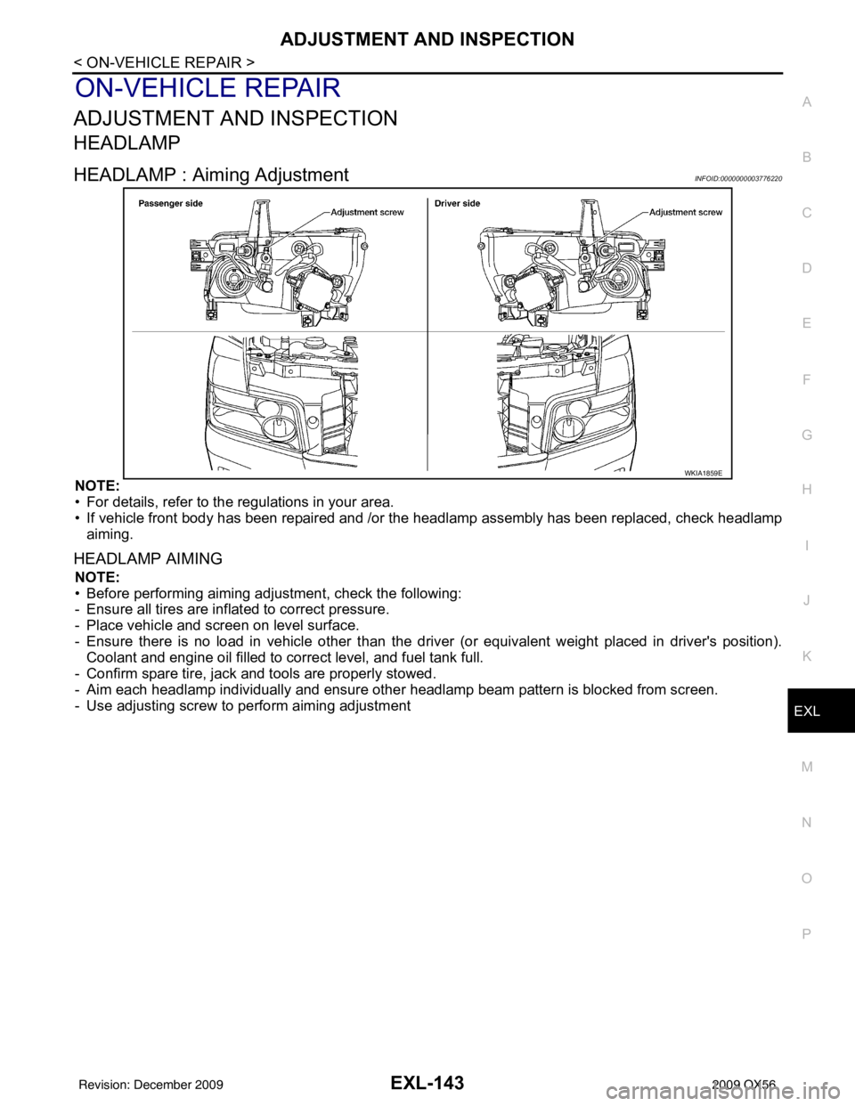
HEADLAMP : Aiming AdjustmentINFOID:0000000003776220
NOTE:
• For details, refer to the regulations in your area.
• If vehicle front body has been repaired and /or the headlamp assembly has been replaced, check headlamp
aiming.
HEADLAMP AIMING
NOTE:
• Before performing aiming adjustment, check the following:
- Ensure all tires are inflated to correct pressure.
- Place vehicle and screen on level surface.
- Ensure there is no load in vehicle other than the driver (or equivalent weight placed in driver's position). Coolant and engine oil filled to correct level, and fuel tank full.
- Confirm spare tire, jack and tools are properly stowed.
- Aim each headlamp individually and ensure other headlamp beam pattern is blocked from screen.
- Use adjusting screw to perform aiming adjustment
WKIA1859E
Revision: December 20092009 QX56